EP1529239B1 - Transflektive flüssigkristallanzeigeeinrichtung - Google Patents
Transflektive flüssigkristallanzeigeeinrichtung Download PDFInfo
- Publication number
- EP1529239B1 EP1529239B1 EP03784331A EP03784331A EP1529239B1 EP 1529239 B1 EP1529239 B1 EP 1529239B1 EP 03784331 A EP03784331 A EP 03784331A EP 03784331 A EP03784331 A EP 03784331A EP 1529239 B1 EP1529239 B1 EP 1529239B1
- Authority
- EP
- European Patent Office
- Prior art keywords
- liquid crystal
- pixel
- layer
- display device
- cholesteric
- Prior art date
- Legal status (The legal status is an assumption and is not a legal conclusion. Google has not performed a legal analysis and makes no representation as to the accuracy of the status listed.)
- Expired - Lifetime
Links
- 239000004973 liquid crystal related substance Substances 0.000 title claims abstract description 51
- 230000003098 cholesteric effect Effects 0.000 claims abstract description 61
- 239000000203 mixture Substances 0.000 claims abstract description 39
- 239000000758 substrate Substances 0.000 claims abstract description 21
- 239000003086 colorant Substances 0.000 claims abstract description 12
- 230000003287 optical effect Effects 0.000 claims abstract description 3
- 239000011159 matrix material Substances 0.000 claims description 8
- 230000000979 retarding effect Effects 0.000 claims 1
- 238000004519 manufacturing process Methods 0.000 description 11
- 230000015572 biosynthetic process Effects 0.000 description 5
- 239000002131 composite material Substances 0.000 description 2
- 238000005286 illumination Methods 0.000 description 2
- 238000000059 patterning Methods 0.000 description 2
- 238000004064 recycling Methods 0.000 description 2
- 238000001228 spectrum Methods 0.000 description 2
- 238000010521 absorption reaction Methods 0.000 description 1
- 230000001413 cellular effect Effects 0.000 description 1
- 230000031700 light absorption Effects 0.000 description 1
- 238000000034 method Methods 0.000 description 1
- 229920001690 polydopamine Polymers 0.000 description 1
Images


Classifications
-
- G—PHYSICS
- G02—OPTICS
- G02F—OPTICAL DEVICES OR ARRANGEMENTS FOR THE CONTROL OF LIGHT BY MODIFICATION OF THE OPTICAL PROPERTIES OF THE MEDIA OF THE ELEMENTS INVOLVED THEREIN; NON-LINEAR OPTICS; FREQUENCY-CHANGING OF LIGHT; OPTICAL LOGIC ELEMENTS; OPTICAL ANALOGUE/DIGITAL CONVERTERS
- G02F1/00—Devices or arrangements for the control of the intensity, colour, phase, polarisation or direction of light arriving from an independent light source, e.g. switching, gating or modulating; Non-linear optics
- G02F1/01—Devices or arrangements for the control of the intensity, colour, phase, polarisation or direction of light arriving from an independent light source, e.g. switching, gating or modulating; Non-linear optics for the control of the intensity, phase, polarisation or colour
- G02F1/13—Devices or arrangements for the control of the intensity, colour, phase, polarisation or direction of light arriving from an independent light source, e.g. switching, gating or modulating; Non-linear optics for the control of the intensity, phase, polarisation or colour based on liquid crystals, e.g. single liquid crystal display cells
- G02F1/133—Constructional arrangements; Operation of liquid crystal cells; Circuit arrangements
- G02F1/1333—Constructional arrangements; Manufacturing methods
- G02F1/1335—Structural association of cells with optical devices, e.g. polarisers or reflectors
- G02F1/133553—Reflecting elements
- G02F1/133555—Transflectors
-
- G—PHYSICS
- G02—OPTICS
- G02F—OPTICAL DEVICES OR ARRANGEMENTS FOR THE CONTROL OF LIGHT BY MODIFICATION OF THE OPTICAL PROPERTIES OF THE MEDIA OF THE ELEMENTS INVOLVED THEREIN; NON-LINEAR OPTICS; FREQUENCY-CHANGING OF LIGHT; OPTICAL LOGIC ELEMENTS; OPTICAL ANALOGUE/DIGITAL CONVERTERS
- G02F2201/00—Constructional arrangements not provided for in groups G02F1/00 - G02F7/00
- G02F2201/34—Constructional arrangements not provided for in groups G02F1/00 - G02F7/00 reflector
- G02F2201/343—Constructional arrangements not provided for in groups G02F1/00 - G02F7/00 reflector cholesteric liquid crystal reflector
Definitions
- This invention relates to a transflective liquid crystal display device, having a plurality of pixels, each comprising a liquid crystal layer being sandwiched between a front ana a back substrate, a back light, a semi-transparent reflective element, being arranged between the back substrate and the back light, a front polariser, and a driving arrangement for controlling optical properties of the liquid crystal layer, whereby the pixel is subdivided into a reflective pixel part and a transmissive pixel part.
- LCDs Due to its low power consumption, reliability and low price, liquid crystal displays, or LCDs, have become the standard display choice for many applications, for example mobile applications, such as PDAs, laptops and cellular telephones.
- Different LCD types such as passive or active matrix displays and reflective or transmissive displays are currently available on the market.
- Reflective LCDs are especially suited for outdoor use in direct sunlight.
- the contrast ratio of such a display is relatively low, compared with a transmissive display, and under poor illumination conditions, the brightness of this kind of display is low.
- transmissive LCDs have a good contrast ratio, but they become practically unreadable under direct sunlight illumination conditions.
- the transmissive display utilizes a backlight, resulting in an increase of the power consumption.
- transflective displays having both transmissive and reflective properties have been developed.
- most such displays comprises a transflective semitransparent mirror member in the back of the pixel, the entire pixel thereby constituting a transflective unit.
- recently transflective displays have been developed, wherein each pixel comprises a reflective pixel part and a transmissive pixel part, hence achieving transflective operation.
- One example of such a display is disclosed in the article "Development of advanced TFT with good legibility under any intensity of ambient light; Masumi Kubo et. Al; Sharp Corp, IDW '99". This article discloses a display in which each pixel comprises a reflective structure and a transmissive structure.
- an object of the present invention is to achieve a transflective liquid crystal display device having an alternative configuration, overcoming at least some of the drawbacks with the prior art.
- a transflective liquid crystal device as described by way of introduction, being characterised in that a first cholesteric layer composition is arranged between said liquid crystal layer and the back substrate, said cholesteric layer composition comprising, in said reflective pixel part, a first cholesteric layer composition part for reflecting a desired primary pixel colour, and in said transmissive pixel part, a second cholesteric layer composition part for reflecting the remaining primary colours, other than said desired primary pixel colour.
- the second cholesteric layer composition part comprises a first and a second layer, wherein the first layer is arranged to reflect light of a first remaining primary colour, and the second layer is arranged to reflect light of a second remaining primary colour.
- a structure has the advantage that it is comparatively easy to manufacture. It may be manufactured by applying two cholesteric manufacturing layers all over the display structure, i.e. in both the reflective and the transmissive parts of the pixels, and patterning each layer individually. First, a first layer is applied to the structure, which layer is patterned by means of colour formation through a photo mask, so that the layer is patterned to reflect the desired primary pixel colour in the reflective part of the pixel, and a first remaining primary colour in the transmissive part.
- a second cholesteric manufacturing layer is applied on the first layer, which layer is patterned by means of colour formation through a photo mask, so that the layer is pattern to reflect the desired primary pixel colour in the reflective part of the pixel, and a second remaining primary colour in the transmissive part.
- the reflective part comprises a composite cholesteric layer structure, reflecting a desired primary colour, such as "Green”, (due to the manufacturing, the reflective part in this case comprises two layers, both reflecting "Green") while the transmissive part comprises a layered structure, in which each layer reflects a certain remaining primary colour, such as "Blue” and “Red", respectively.
- This is a comparatively easy way of achieving a reflective layer, for reflecting several wavelength intervals.
- the pixel further comprises an absorbing colour filter between said liquid crystal layer and said cholesteric colour filter composition, said absorbing colour filter being arranged to absorb the undesired colours of in-falling ambient light.
- said absorbing colour filter being arranged to absorb the undesired colours of in-falling ambient light.
- said pixel further comprises an in-cell quarterwave retarder plate and an in-cell polariser, both being arranged between the liquid crystal layer and the cholesteric layer composition. This improves the black state of the reflective and transmissive mode. Also, the above two described preferred embodiments may be combined, thereby achieving all of the advantages mentioned above.
- an absorbing layer is arranged in the reflective pixel part, between the first cholesteric layer composition part and the back substrate.
- all incoming light, that has not already been reflected by the cholesteric layer in the reflective part will be absorbed.
- light generated by the backlight will be absorbed before entering the cholesteric layer of the reflective part of the display, and will hence not degrade the colour purity of the pixel part.
- the inclusion of such an absorbing layer will hence not be needed if the display device comprises the quarterwave retarder, the polariser as well as the absorbing colour filter, as described above, since in this case all unwanted light will already have been absorbed, either by the absorbing colour filter or the polariser.
- a mirror element is arranged between the absorbing layer and the back substrate. Thereby, light generated by the backlight will be reflected back to the backlight, and hence be recycled, improving the efficiency of the backlight.
- said liquid crystal layer is arranged to act as a ⁇ /2 plate changing the handed-ness of circular polarised light.
- the liquid crystal layer may be of any conventional type.
- twisted nematic (TN), supertwisted nematic (STN), ferro-electric (FLC), electrically compensated birefringence (ECB) and vertically aligned nematic (VAN) liquid crystal configurations may be used.
- a reflective layer is suitably arranged on a back side of said back substrate, said reflective layer being a reflective circular polariser.
- said driving arrangement is one of an active matrix driving arrangement or a passive matrix driving arrangement, and hence the inventive solution is very flexible.
- said first and second cholesteric layer composition parts occupy essentially the same cell gap, which enables easy manufacturing by means of photo mask formation as indicated above.
- the display device will hereinafter be described with reference to a single pixel of the display device, in the present case a green pixel.
- the display device may however comprise a plurality of pixels, for example a plurality of green, red and blue pixels, in order to generate a full colour display.
- the invention is equally applicable to pixels of any colour, and for a red and a blue pixel, for example, the colours of the cholesteric colour filter, and any colour filter are changed in such a way, in relation to the below description, that the pixel is red or blue, respectively, in the reflective mode as well as the transmissive mode, instead of green as in the present case. Also, the choice of primary colours red, green and blue is not essential for the invention, but any colour combination together defining a full colour spectrum may be used.
- a cross section of a design for a single pixel 1 of a transflective liquid crystal device (LCD) with a cholesteric colour filter in accordance with the invention is disclosed in fig 1.
- the pixel 1 essentially comprises a liquid crystal (LC) layer 2, being controlled by means of a TFT layer 3. Behind the LC layer 2, as seen from a viewer of the display, a cholesteric layer composition 11, 12 is arranged. This layer will be closer described below.
- the stack comprising the LC layer 2 and the cholesteric layer composition 11, 12 is sandwiched between a front and a back substrate 4, 5. Behind the back substrate, a reflecting circular polariser 7 is arranged.
- a linear polariser 6 and a ⁇ /4 retarder 8 is arranged, the retarder 8 being arranged behind the polariser 6 and the front substrate 4.
- a backlight 9 is arranged.
- the pixel 1 is further subdivided into two parts, a reflective pixel part 1a and a transmissive pixel part 1b. The subdivision is made by means of altering the cholesteric layer composition in the reflective and transmissive parts of the display.
- the layer composition comprises a first cholesteric layer composition part 11, in the present case being arranged to reflect light of the colour green, i.e. the desired primary colour of the pixel.
- a first cholesteric layer composition part 11 Between the first cholesteric layer composition part 11 and the back substrate an absorbing layer 9, such as a black layer is arranged.
- a mirror element 14 may be positioned between the absorbing layer 9 and the back substrate 5, in order to enhance light recycling in the back-light by avoiding absorption of light emanating from the backlight by said absorbing layer 9.
- the cholesteric layer composition comprises a second cholesteric layer composition part 12, being subdivided into two sub-layers, one for reflecting blue light and one for reflecting red light, i.e. the remaining primary colours of the pixel (other than the desired pixel colour green). Both sub-layers extend in parallel over virtually the entire transmissive pixel part.
- a cholesteric colour filter being sub-divided into several parts as in the present invention. It may be manufactured by applying two cholesteric manufacturing layers all over the display structure, i.e. in both the reflective and the transmissive parts of the pixels, and patterning each layer individually.
- a first layer is applied to the structure, which layer is patterned by means of colour formation through a photo mask, so that the layer is pattern to reflect the desired primary pixel colour in the reflective part of the pixel, and a first remaining primary colour in the transmissive part.
- a second cholesteric manufacturing layer is applied on the first layer, which layer is patterned by means of colour formation through a photo mask, so that the layer is patterned to reflect the desired primary pixel colour in the reflective part of the pixel, and a second remaining primary colour in the transmissive part.
- the reflective part comprises a composite cholesteric layer structure, reflecting a desired primary colour, such as "Green”, (due to the manufacturing, the reflective part in this case comprises two layers, both reflecting "Green") while the transmissive part comprises a layered structure, in which each layer reflects a certain remaining primary colour, such as "Blue” and "Red”, respectively.
- the reflective pixel part 1a of the transflective pixel has the normal configuration for a reflective LCD with a cholesteric colour filter.
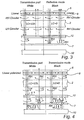
- the path of the polarized light entering the display pixel 1 is shown in fig 2, both when the pixel part is in a ''white'' state (i.e. reflecting the colour green) as seen to the left in fig 2, and when the pixel part is in a "black" state, as seen to the right in fig 2.
- the first cholesteric layer composition part 11 is in this case arranged to reflect green left-handed polarized light.
- the linear polariser 6 and the ⁇ /4 plate 8 are combined in such a way that right handed circular polarized light is generated.
- the liquid crystal layer 2 which is arranged to act as a ⁇ /2 plate in one switching position (as shown to the left in fig 2), changes the right-handed circular polarised light into left-handed polarized light. Subsequently, the light reaches the cholesteric colour filter, and left-handed green light is reflected, while the remaining light is transmitted through the first cholesteric layer composition part 11 and absorbed by the absorbing layer 9. The reflected green left-handed polarized light is again changed to right-handed polarized light when passing the liquid crystal layer 2, and is subsequently transmitted through the ⁇ /4 plate 8 and the linear polariser 6.
- the retardation of the LC layer 2 is switched to zero (right part of fig 2), the right-handed polarized light falling onto the layer is not changed. Hence, the right-handed polarized light is transmitted through the cholesteric layer 11 and is absorbed by the absorption layer 9. In this way, the pixel becomes "black".
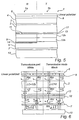
- the transmissive pixel part 1b of the pixel has the configuration for a transmissive LCD with cholesteric colour filters.
- the reflective circular polarizer 7 is in this case a right-handed reflective circular polariser and reflects right-handed circular polarized light from the backlight and transmits left-handed circular polarized light.
- the reflected right-handed polarised light may be recycled in the backlight.
- the red and blue reflecting cholesteric sub-layers 12a, 12b respectively reflects the red and the blue left-handed polarised daylight and the green left-handed polarised daylight is transmitted through the second cholesteric layer composition part 12 (see the left part of fig 4).
- the green left-handed polarized daylight may be recycled in the backlight, while the reflected blue and red left-handed polarized daylight reduces the colour purity of the pixel.
- a first alternative embodiment of this invention will hereinafter be described with reference to fig 5-7.
- This embodiment is essentially similar to the one disclosed in fig 1 and closely described above, but further includes an absorbing colour filter 13, in the present case being arranged between the liquid crystal layer 2 and the cholesteric layers 11, 12.
- the absorbing colour filter is arranged to absorb all colours but the desired primary colour of the pixel, in this case the colour green.
- the green transmissive light coming from the backlight will be mixed with red and blue reflected ambient light, which lowers the colour purity of the transmissive part of the pixel.
- This may be prevented by adding the above absorbing colour filter 13 to the stack, since this layer will absorb all red and blue ambient light, falling into the transmissive part of the display, and this light will hence not add to the colour of the pixel.
- an absorbing colour filter prevents colour mixing by daylight in the transmissive mode. Hence, it improves the daylight contrast and prevents the decrease of colour purity by reflection of daylight on the red and blue layer of the cholesteric colour filter 12. It also prevents a colour shift of the display at large viewing angles. All light which is reflected at large angles is shifted to a shorter wavelength by the cholesteric colour filter of this invention. Hence, this light will be absorbed by the absorbing colour filter.
- fig 6 transmissive mode
- fig 7 reflective part or display in reflective mode
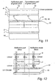
- a second alternative embodiment will hereinafter be described with reference to fig 8-10.
- This embodiment is essentially similar to, the one disclosed in fig 1 and closely described above, but further includes an in-cell ⁇ /4 film 15 and an in-cell polariser 16 between the liquid crystal layer 2 and the cholesteric layer composition 11, 12, and further the ⁇ /4 film 8 of the configuration shown in fig 1 is removed.
- the reflection of white daylight in the black state of the transmissive part 1b of the pixel 1 may be deleted, as is disclosed in fig 10.
- circularly polarised light is changed to linear polarized light by the ⁇ /4 film 15 and is transmitted through the in-cell polariser 16.
- the top polariser 6 is rotated 90° with respect to the in-cell polariser 16, i.e. the polarisers 6, 16 are crossed.
- the liquid crystal layer 2, acting as a ⁇ /2 plate, rotates the plane of polarisation by 90° and the light is transmitted through the top polariser. If the LC layer is switched, the plane of polarisation is not changed in the above manner and the light is hence absorbed by the top polariser (see fig 10).
- all linearly polarised daylight is absorbed by the in-cell polariser 16, as is shown in fig 9 and 10 for the reflective and transmissive part of the pixel, respectively. In the black state of the reflective part of the pixel (see fig 9), all linearly polarised light will be absorbed by the in-cell polariser.
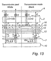
- a third alternative embodiment of this invention is to combine the first and second alternative embodiments, and hence add an absorbing colour filter, an in-cell ⁇ /4 film 15 and an in-cell polariser 16 to the stack shown in fig 1, while removing the front ⁇ /4 film 8, and suitably also the absorbing layer 9 (removed in fig 11), which by reasons stated above is not needed.
- This embodiment is disclosed in fig 11, with corresponding beam path patterns in fig 12 (reflective pixel part in reflective mode) and fig 13 (transmissive pixel part in transmissive mode). In this case all undesired reflections of ambient light is absorbed, either by the absorbing colour filter or the polariser.
- the invention is equally applicable in an passive matrix transflective LCD.
- the TFT layer 3, for example disclosed in fig 1 is replaced by an electrode layer, such as an ITO electrode, and if an absorbing colour filter is to be arranged in the pixel stack, it may be placed between the front substrate and the ITO layer.
- a problem with prior art transflective LCD using cholesteric layers in some form is that they normally show a reverse image in the transmissive and reflective mode. However, this is not the case with the displays disclosed here.
- the display is black in both the transmissive and reflective mode. In the non-driven state of the pixel, the display is "white" (in the case above, green) in the transmissive as well as in the reflective mode.
- the transmissive and reflective parts 1a, 1b of the pixel are of equal size.
- the reflective part is usually larger than the transmissive part of the display. This results in that the mixing of blue and red light in a green ("white") state of the reflective mode, and addition of white light in the black state of the reflective and transmissive mode is somewhat reduced, due to a smaller reflection area.
- the above description of the invention is aimed towards a display in which left-handed circularly polarised light is reflective.
- a man skilled in the art may easily adapt the above inventive structure to instead reflect right-handed, circularly polarised light.
- the display device has above been described with reference to a single pixel of the display device, in the present case a green pixel.
- the display device may however comprise a plurality of pixels, for example a plurality of green, red and blue pixels, in order to generate a full colour display.
- the invention is equally applicable to pixels of any colour, and for a red and a blue pixel, for example, the colours of the cholesteric colour filter, and any colour filter are changed in such a way, in relation to the below description, that the pixel is red or blue, respectively, in the reflective mode as well as the transmissive mode, instead of green as in the present case.
- each pixel shall be designed to emit light of a primary colour, while suppressing light of the remaining primary colours.
- the colours of the pixel may be chosen in any way that defines a full colour spectrum, and shall not be limited to red, green and blue.
- wavelength shall be construed as a wavelength or a wavelength interval.
- a "colour" as used in this application shall be construed as covering a wavelength or a wavelength interval.
Landscapes
- Physics & Mathematics (AREA)
- Nonlinear Science (AREA)
- Mathematical Physics (AREA)
- Chemical & Material Sciences (AREA)
- Crystallography & Structural Chemistry (AREA)
- General Physics & Mathematics (AREA)
- Optics & Photonics (AREA)
- Liquid Crystal (AREA)
- Polarising Elements (AREA)
- Optical Filters (AREA)
Claims (10)
- Transflektive Flüssigkristallanzeigeeinrichtung, welche eine große Anzahl Pixel (1) aufweist, die jeweils eine Flüssigkristallschicht (2), welche zwischen einem vorderen (4) und einem hinteren (5) Substrat angeordnet ist, eine Hintergrundbeleuchtung, ein halbdurchlässiges, reflektives Element (7), welche zwischen dem hinteren Substrat und der Hintergrundbeleuchtung angeordnet ist, einen vorderen Polarisator (6), eine Steueranordnung (3) zur Steuerung der optischen Eigenschaften der Flüssigkristallschicht sowie eine cholesterische Schichtzusammensetzung, welche zwischen der Flüssigkristallschicht und dem hinteren Substrat angeordnet ist, aufweisen, wobei das Pixel in einen reflektiven Pixelteil (1a) und einen transmissiven Pixelteil (1b) unterteilt ist,
dadurch gekennzeichnet, dass
die cholesterische Schichtzusammensetzung aufweist:einen ersten cholesterischen Schichtzusammensetzungsteil (11) in dem reflektiven Pixelteil (1a), um eine gewünschte Pixelprimärfarbe zu reflektieren, sowieeinen zweiten cholesterischen Schichtzusammensetzungsteil (12) in dem transmissiven Pixelteil (1b), um die verbleibenden Primärfarben, d.h. die anderen als die gewünschte Pixelprimärfarbe, zu reflektieren. - Transflektive Flüssigkristallanzeigeeinrichtung nach Anspruch 1, wobei der zweite cholesterische Schichtzusammensetzungsteil (12) eine erste (12a) und eine zweite (12b) Schicht aufweist, wobei die erste Schicht so angeordnet ist, dass sie Licht einer ersten verbleibenden Primärfarbe reflektiert, und die zweite Schicht so angeordnet ist, dass sie Licht einer zweiten verbleibenden Primärfarbe reflektiert.
- Transflektive Flüssigkristallanzeigeeinrichtung nach Anspruch 1 oder 2, wobei das Pixel weiterhin ein Farbabsorptionsfilter (13) aufweist, welches zwischen der Flüssigkristallschicht und der cholesterischen Farbfilterzusammensetzung angeordnet ist, wobei das Farbabsorptionsfilter so angeordnet ist, dass es die restlichen Primärfarben absorbiert, wobei lediglich eine gewünschte Pixelprimärfarbe übertragen wird.
- Transflektive Flüssigkristallanzeigeeinrichtung nach einem der vorangegangenen Ansprüche, wobei das Pixel weiterhin eine, in der Zelle vorgesehene Viertelwellen-Verzögerungsplatte (8) und einen, in der Zelle vorgesehenen Polarisator (16) aufweist, wobei beide zwischen der Flüssigkristallschicht (2) und der cholesterischen Schichtzusammensetzung angeordnet sind.
- Transflektive Flüssigkristallanzeigeeinrichtung nach einem der vorangegangenen Ansprüche, wobei eine Absorptionsschicht (9) in dem reflektiven Pixelteil zwischen dem ersten cholesterischen Schichtzusammensetzungsteil und dem hinteren Substrat angeordnet ist.
- Transflektive Flüssigkristallanzeigeeinrichtung nach Anspruch 5, wobei ein Spiegelelement (14) zwischen der Absorptionsschicht und dem hinteren Substrat angeordnet ist.
- Transflektive Flüssigkristallanzeigeeinrichtung nach einem der vorangegangenen Ansprüche, wobei die Flüssigkristallschicht so angeordnet ist, dass sie als λ/2-Verzögerungsplatte wirkt.
- Transflektive Flüssigkristallanzeigeeinrichtung nach einem der vorangegangenen Ansprüche, wobei das halbdurchlässige, reflektive Element durch einen reflektiven, zirkularen Polarisator (7) gebildet wird.
- Transflektive Flüssigkristallanzeigeeinrichtung nach einem der vorangegangenen Ansprüche, wobei die Steueranordnung durch eine Steueranordnung mit aktiver Matrix oder eine Steueranordnung mit passiver Matrix dargestellt ist.
- Transflektive Flüssigkristallanzeigeeinrichtung nach einem der vorangegangenen Ansprüche, wobei der erste und der zweite cholesterische Schichtzusammensetzungsteil im Wesentlichen den gleichen Zellenzwischenraum beanspruchen.
Priority Applications (1)
| Application Number | Priority Date | Filing Date | Title |
|---|---|---|---|
| EP03784331A EP1529239B1 (de) | 2002-08-02 | 2003-07-22 | Transflektive flüssigkristallanzeigeeinrichtung |
Applications Claiming Priority (4)
| Application Number | Priority Date | Filing Date | Title |
|---|---|---|---|
| EP02078172 | 2002-08-02 | ||
| EP02078172 | 2002-08-02 | ||
| PCT/IB2003/003178 WO2004015486A1 (en) | 2002-08-02 | 2003-07-22 | Transflective liquid crystal display device |
| EP03784331A EP1529239B1 (de) | 2002-08-02 | 2003-07-22 | Transflektive flüssigkristallanzeigeeinrichtung |
Publications (2)
| Publication Number | Publication Date |
|---|---|
| EP1529239A1 EP1529239A1 (de) | 2005-05-11 |
| EP1529239B1 true EP1529239B1 (de) | 2005-12-14 |
Family
ID=31502771
Family Applications (1)
| Application Number | Title | Priority Date | Filing Date |
|---|---|---|---|
| EP03784331A Expired - Lifetime EP1529239B1 (de) | 2002-08-02 | 2003-07-22 | Transflektive flüssigkristallanzeigeeinrichtung |
Country Status (10)
| Country | Link |
|---|---|
| US (1) | US7173679B2 (de) |
| EP (1) | EP1529239B1 (de) |
| JP (1) | JP2005534989A (de) |
| KR (1) | KR20050033643A (de) |
| CN (1) | CN1672090A (de) |
| AT (1) | ATE313101T1 (de) |
| AU (1) | AU2003247047A1 (de) |
| DE (1) | DE60302801T2 (de) |
| TW (1) | TWM250177U (de) |
| WO (1) | WO2004015486A1 (de) |
Families Citing this family (15)
| Publication number | Priority date | Publication date | Assignee | Title |
|---|---|---|---|---|
| DE602004014000D1 (de) * | 2003-09-19 | 2008-07-03 | Tpo Hong Kong Holding Ltd | Transflektives display mit verbessertem kontrast |
| KR20050045433A (ko) * | 2003-11-11 | 2005-05-17 | 삼성전자주식회사 | 표시장치 |
| JP4228973B2 (ja) * | 2004-04-08 | 2009-02-25 | セイコーエプソン株式会社 | 液晶表示装置および電子機器 |
| JP4223992B2 (ja) | 2004-05-25 | 2009-02-12 | 株式会社 日立ディスプレイズ | 液晶表示装置 |
| EP1873577A1 (de) * | 2005-03-29 | 2008-01-02 | Mitsubishi Chemical Corporation | Polarisiererzusammensetzung des in-zellen-typs, polarisierer des in-zellen-typs, geschichteter lichtpolarisierer des in-zellen-typs und flüssigkristallelement damit |
| TWI258039B (en) * | 2005-05-09 | 2006-07-11 | Chi Mei Optoelectronics Corp | Display panel and liquid crystal display device |
| US7746294B2 (en) * | 2006-04-14 | 2010-06-29 | University Of Central Florida Research Foundation, Inc. | Transflective liquid crystal display |
| JP2008203382A (ja) * | 2007-02-19 | 2008-09-04 | Hitachi Displays Ltd | 液晶表示装置 |
| JP4638462B2 (ja) * | 2007-03-26 | 2011-02-23 | 株式会社 日立ディスプレイズ | 液晶表示装置 |
| JP2008268844A (ja) * | 2007-03-28 | 2008-11-06 | Epson Imaging Devices Corp | 液晶表示装置および電子機器 |
| US8018554B2 (en) * | 2007-03-28 | 2011-09-13 | Sony Corporation | Liquid crystal display device with internal retardation layer at reflection region and electronic apparatus |
| KR20120085058A (ko) * | 2011-01-21 | 2012-07-31 | 삼성전자주식회사 | 반사형 표시장치 |
| CN108227319B (zh) * | 2018-01-23 | 2021-02-05 | 京东方科技集团股份有限公司 | 一种显示面板及显示装置 |
| US11778856B2 (en) | 2019-05-15 | 2023-10-03 | Apple Inc. | Electronic device having emissive display with light recycling |
| US20240264441A1 (en) * | 2023-02-07 | 2024-08-08 | Avner Bendheim | System, apparatus, and method for integration of facial nonverbal communication in extravehicular activity or space operations |
Family Cites Families (7)
| Publication number | Priority date | Publication date | Assignee | Title |
|---|---|---|---|---|
| US5841494A (en) * | 1996-06-26 | 1998-11-24 | Hall; Dennis R. | Transflective LCD utilizing chiral liquid crystal filter/mirrors |
| JP2000131684A (ja) * | 1998-10-22 | 2000-05-12 | Toshiba Corp | 液晶表示素子 |
| KR100586242B1 (ko) * | 2000-01-06 | 2006-06-02 | 엘지.필립스 엘시디 주식회사 | 반사투과형 액정표시장치와 그 제조방법 |
| AU2001271318A1 (en) * | 2000-06-26 | 2002-01-08 | Reveo, Inc. | Cholesteric liquid crystal polarizing device |
| JP3941481B2 (ja) * | 2000-12-22 | 2007-07-04 | セイコーエプソン株式会社 | 液晶表示装置および電子機器 |
| KR100394988B1 (ko) * | 2001-02-14 | 2003-08-19 | 엘지.필립스 엘시디 주식회사 | 콜레스테릭 액정 컬러필터를 이용한 반사형 액정표시장치 |
| JP3675397B2 (ja) * | 2001-12-07 | 2005-07-27 | セイコーエプソン株式会社 | 反射板、液晶表示装置、電子機器 |
-
2003
- 2003-07-22 EP EP03784331A patent/EP1529239B1/de not_active Expired - Lifetime
- 2003-07-22 AT AT03784331T patent/ATE313101T1/de not_active IP Right Cessation
- 2003-07-22 DE DE60302801T patent/DE60302801T2/de not_active Expired - Fee Related
- 2003-07-22 CN CNA03818446XA patent/CN1672090A/zh active Pending
- 2003-07-22 KR KR1020057001852A patent/KR20050033643A/ko not_active Withdrawn
- 2003-07-22 US US10/523,621 patent/US7173679B2/en not_active Expired - Fee Related
- 2003-07-22 JP JP2004527139A patent/JP2005534989A/ja not_active Withdrawn
- 2003-07-22 AU AU2003247047A patent/AU2003247047A1/en not_active Abandoned
- 2003-07-22 WO PCT/IB2003/003178 patent/WO2004015486A1/en not_active Ceased
- 2003-07-30 TW TW092213864U patent/TWM250177U/zh unknown
Also Published As
| Publication number | Publication date |
|---|---|
| JP2005534989A (ja) | 2005-11-17 |
| EP1529239A1 (de) | 2005-05-11 |
| KR20050033643A (ko) | 2005-04-12 |
| US20060001804A1 (en) | 2006-01-05 |
| ATE313101T1 (de) | 2005-12-15 |
| CN1672090A (zh) | 2005-09-21 |
| DE60302801D1 (de) | 2006-01-19 |
| DE60302801T2 (de) | 2006-08-10 |
| WO2004015486A1 (en) | 2004-02-19 |
| TWM250177U (en) | 2004-11-11 |
| AU2003247047A1 (en) | 2004-02-25 |
| US7173679B2 (en) | 2007-02-06 |
Similar Documents
| Publication | Publication Date | Title |
|---|---|---|
| US6330100B2 (en) | Display device with transflective electrode | |
| KR100621495B1 (ko) | 화상 표시 상태와 거울 상태를 전환 가능한 장치, 및이것을 구비한 기기 | |
| JP3717054B2 (ja) | 透過反射型液晶ディスプレイ | |
| EP1529239B1 (de) | Transflektive flüssigkristallanzeigeeinrichtung | |
| US6693689B1 (en) | Reflective liquid crystal display device | |
| US6747717B2 (en) | Liquid crystal display device having cholesteric liquid crystal | |
| KR20010109333A (ko) | 액정표시장치 | |
| US6671016B1 (en) | Transmission-reflection type liquid crystal display device having a selectively reflective filter layer | |
| JP2001056463A (ja) | 液晶表示装置 | |
| JP3410663B2 (ja) | 液晶表示装置 | |
| JP3215339B2 (ja) | 液晶表示装置 | |
| US6833889B2 (en) | Cholesteric liquid crystal display device with reflectors and manufacturing method for the same | |
| KR101250878B1 (ko) | 액정표시장치 | |
| US7646454B2 (en) | Transflective liquid crystal display device | |
| JP3619506B2 (ja) | 液晶表示装置 | |
| JP2004258527A (ja) | 液晶表示装置 | |
| JPH0961854A (ja) | カラー液晶表示素子 | |
| JP3619507B2 (ja) | 液晶表示装置 | |
| JP3289370B2 (ja) | カラー液晶表示装置 | |
| JPH10206880A (ja) | 液晶表示素子及びその駆動方法 | |
| JPH10268296A (ja) | カラー液晶表示装置 |
Legal Events
| Date | Code | Title | Description |
|---|---|---|---|
| PUAI | Public reference made under article 153(3) epc to a published international application that has entered the european phase |
Free format text: ORIGINAL CODE: 0009012 |
|
| 17P | Request for examination filed |
Effective date: 20050302 |
|
| AK | Designated contracting states |
Kind code of ref document: A1 Designated state(s): AT BE BG CH CY CZ DE DK EE ES FI FR GB GR HU IE IT LI LU MC NL PT RO SE SI SK TR |
|
| AX | Request for extension of the european patent |
Extension state: AL LT LV MK |
|
| GRAP | Despatch of communication of intention to grant a patent |
Free format text: ORIGINAL CODE: EPIDOSNIGR1 |
|
| GRAS | Grant fee paid |
Free format text: ORIGINAL CODE: EPIDOSNIGR3 |
|
| GRAA | (expected) grant |
Free format text: ORIGINAL CODE: 0009210 |
|
| DAX | Request for extension of the european patent (deleted) | ||
| AK | Designated contracting states |
Kind code of ref document: B1 Designated state(s): AT BE BG CH CY CZ DE DK EE ES FI FR GB GR HU IE IT LI LU MC NL PT RO SE SI SK TR |
|
| PG25 | Lapsed in a contracting state [announced via postgrant information from national office to epo] |
Ref country code: AT Free format text: LAPSE BECAUSE OF FAILURE TO SUBMIT A TRANSLATION OF THE DESCRIPTION OR TO PAY THE FEE WITHIN THE PRESCRIBED TIME-LIMIT Effective date: 20051214 Ref country code: SK Free format text: LAPSE BECAUSE OF FAILURE TO SUBMIT A TRANSLATION OF THE DESCRIPTION OR TO PAY THE FEE WITHIN THE PRESCRIBED TIME-LIMIT Effective date: 20051214 Ref country code: RO Free format text: LAPSE BECAUSE OF FAILURE TO SUBMIT A TRANSLATION OF THE DESCRIPTION OR TO PAY THE FEE WITHIN THE PRESCRIBED TIME-LIMIT Effective date: 20051214 Ref country code: CZ Free format text: LAPSE BECAUSE OF FAILURE TO SUBMIT A TRANSLATION OF THE DESCRIPTION OR TO PAY THE FEE WITHIN THE PRESCRIBED TIME-LIMIT Effective date: 20051214 Ref country code: CH Free format text: LAPSE BECAUSE OF FAILURE TO SUBMIT A TRANSLATION OF THE DESCRIPTION OR TO PAY THE FEE WITHIN THE PRESCRIBED TIME-LIMIT Effective date: 20051214 Ref country code: IT Free format text: LAPSE BECAUSE OF FAILURE TO SUBMIT A TRANSLATION OF THE DESCRIPTION OR TO PAY THE FEE WITHIN THE PRESCRIBED TIME-LIMIT;WARNING: LAPSES OF ITALIAN PATENTS WITH EFFECTIVE DATE BEFORE 2007 MAY HAVE OCCURRED AT ANY TIME BEFORE 2007. THE CORRECT EFFECTIVE DATE MAY BE DIFFERENT FROM THE ONE RECORDED. Effective date: 20051214 Ref country code: BE Free format text: LAPSE BECAUSE OF FAILURE TO SUBMIT A TRANSLATION OF THE DESCRIPTION OR TO PAY THE FEE WITHIN THE PRESCRIBED TIME-LIMIT Effective date: 20051214 Ref country code: SI Free format text: LAPSE BECAUSE OF FAILURE TO SUBMIT A TRANSLATION OF THE DESCRIPTION OR TO PAY THE FEE WITHIN THE PRESCRIBED TIME-LIMIT Effective date: 20051214 Ref country code: LI Free format text: LAPSE BECAUSE OF FAILURE TO SUBMIT A TRANSLATION OF THE DESCRIPTION OR TO PAY THE FEE WITHIN THE PRESCRIBED TIME-LIMIT Effective date: 20051214 Ref country code: NL Free format text: LAPSE BECAUSE OF FAILURE TO SUBMIT A TRANSLATION OF THE DESCRIPTION OR TO PAY THE FEE WITHIN THE PRESCRIBED TIME-LIMIT Effective date: 20051214 Ref country code: FI Free format text: LAPSE BECAUSE OF FAILURE TO SUBMIT A TRANSLATION OF THE DESCRIPTION OR TO PAY THE FEE WITHIN THE PRESCRIBED TIME-LIMIT Effective date: 20051214 |
|
| REG | Reference to a national code |
Ref country code: GB Ref legal event code: FG4D |
|
| REG | Reference to a national code |
Ref country code: CH Ref legal event code: EP |
|
| REG | Reference to a national code |
Ref country code: IE Ref legal event code: FG4D |
|
| REF | Corresponds to: |
Ref document number: 60302801 Country of ref document: DE Date of ref document: 20060119 Kind code of ref document: P |
|
| PG25 | Lapsed in a contracting state [announced via postgrant information from national office to epo] |
Ref country code: DK Free format text: LAPSE BECAUSE OF FAILURE TO SUBMIT A TRANSLATION OF THE DESCRIPTION OR TO PAY THE FEE WITHIN THE PRESCRIBED TIME-LIMIT Effective date: 20060314 Ref country code: BG Free format text: LAPSE BECAUSE OF FAILURE TO SUBMIT A TRANSLATION OF THE DESCRIPTION OR TO PAY THE FEE WITHIN THE PRESCRIBED TIME-LIMIT Effective date: 20060314 Ref country code: SE Free format text: LAPSE BECAUSE OF FAILURE TO SUBMIT A TRANSLATION OF THE DESCRIPTION OR TO PAY THE FEE WITHIN THE PRESCRIBED TIME-LIMIT Effective date: 20060314 Ref country code: GR Free format text: LAPSE BECAUSE OF FAILURE TO SUBMIT A TRANSLATION OF THE DESCRIPTION OR TO PAY THE FEE WITHIN THE PRESCRIBED TIME-LIMIT Effective date: 20060314 |
|
| PG25 | Lapsed in a contracting state [announced via postgrant information from national office to epo] |
Ref country code: ES Free format text: LAPSE BECAUSE OF FAILURE TO SUBMIT A TRANSLATION OF THE DESCRIPTION OR TO PAY THE FEE WITHIN THE PRESCRIBED TIME-LIMIT Effective date: 20060325 |
|
| PG25 | Lapsed in a contracting state [announced via postgrant information from national office to epo] |
Ref country code: PT Free format text: LAPSE BECAUSE OF FAILURE TO SUBMIT A TRANSLATION OF THE DESCRIPTION OR TO PAY THE FEE WITHIN THE PRESCRIBED TIME-LIMIT Effective date: 20060515 |
|
| NLV1 | Nl: lapsed or annulled due to failure to fulfill the requirements of art. 29p and 29m of the patents act | ||
| PG25 | Lapsed in a contracting state [announced via postgrant information from national office to epo] |
Ref country code: HU Free format text: LAPSE BECAUSE OF FAILURE TO SUBMIT A TRANSLATION OF THE DESCRIPTION OR TO PAY THE FEE WITHIN THE PRESCRIBED TIME-LIMIT Effective date: 20060615 |
|
| REG | Reference to a national code |
Ref country code: CH Ref legal event code: PL |
|
| PG25 | Lapsed in a contracting state [announced via postgrant information from national office to epo] |
Ref country code: IE Free format text: LAPSE BECAUSE OF NON-PAYMENT OF DUE FEES Effective date: 20060724 |
|
| ET | Fr: translation filed | ||
| PG25 | Lapsed in a contracting state [announced via postgrant information from national office to epo] |
Ref country code: MC Free format text: LAPSE BECAUSE OF NON-PAYMENT OF DUE FEES Effective date: 20060731 |
|
| PLBE | No opposition filed within time limit |
Free format text: ORIGINAL CODE: 0009261 |
|
| STAA | Information on the status of an ep patent application or granted ep patent |
Free format text: STATUS: NO OPPOSITION FILED WITHIN TIME LIMIT |
|
| 26N | No opposition filed |
Effective date: 20060915 |
|
| PG25 | Lapsed in a contracting state [announced via postgrant information from national office to epo] |
Ref country code: DE Free format text: LAPSE BECAUSE OF NON-PAYMENT OF DUE FEES Effective date: 20070201 |
|
| REG | Reference to a national code |
Ref country code: FR Ref legal event code: ST Effective date: 20070330 |
|
| GBPC | Gb: european patent ceased through non-payment of renewal fee |
Effective date: 20070722 |
|
| PG25 | Lapsed in a contracting state [announced via postgrant information from national office to epo] |
Ref country code: FR Free format text: LAPSE BECAUSE OF NON-PAYMENT OF DUE FEES Effective date: 20060731 |
|
| PG25 | Lapsed in a contracting state [announced via postgrant information from national office to epo] |
Ref country code: GB Free format text: LAPSE BECAUSE OF NON-PAYMENT OF DUE FEES Effective date: 20070722 |
|
| PG25 | Lapsed in a contracting state [announced via postgrant information from national office to epo] |
Ref country code: EE Free format text: LAPSE BECAUSE OF FAILURE TO SUBMIT A TRANSLATION OF THE DESCRIPTION OR TO PAY THE FEE WITHIN THE PRESCRIBED TIME-LIMIT Effective date: 20051214 |
|
| PG25 | Lapsed in a contracting state [announced via postgrant information from national office to epo] |
Ref country code: LU Free format text: LAPSE BECAUSE OF NON-PAYMENT OF DUE FEES Effective date: 20060722 Ref country code: TR Free format text: LAPSE BECAUSE OF FAILURE TO SUBMIT A TRANSLATION OF THE DESCRIPTION OR TO PAY THE FEE WITHIN THE PRESCRIBED TIME-LIMIT Effective date: 20051214 |
|
| PG25 | Lapsed in a contracting state [announced via postgrant information from national office to epo] |
Ref country code: CY Free format text: LAPSE BECAUSE OF FAILURE TO SUBMIT A TRANSLATION OF THE DESCRIPTION OR TO PAY THE FEE WITHIN THE PRESCRIBED TIME-LIMIT Effective date: 20051214 |