EP1529222B1 - Einrichtung und verfahren zur positionsbestimmung eines transponders - Google Patents
Einrichtung und verfahren zur positionsbestimmung eines transponders Download PDFInfo
- Publication number
- EP1529222B1 EP1529222B1 EP03815795A EP03815795A EP1529222B1 EP 1529222 B1 EP1529222 B1 EP 1529222B1 EP 03815795 A EP03815795 A EP 03815795A EP 03815795 A EP03815795 A EP 03815795A EP 1529222 B1 EP1529222 B1 EP 1529222B1
- Authority
- EP
- European Patent Office
- Prior art keywords
- transmitters
- transponder
- signal
- coil
- facility
- Prior art date
- Legal status (The legal status is an assumption and is not a legal conclusion. Google has not performed a legal analysis and makes no representation as to the accuracy of the status listed.)
- Expired - Lifetime
Links
- 238000000034 method Methods 0.000 title claims description 10
- 230000005672 electromagnetic field Effects 0.000 claims description 3
- 230000008569 process Effects 0.000 claims description 3
- 238000004891 communication Methods 0.000 claims description 2
- 238000011156 evaluation Methods 0.000 abstract description 3
- 230000005540 biological transmission Effects 0.000 description 11
- 238000001514 detection method Methods 0.000 description 4
- 238000013459 approach Methods 0.000 description 3
- 238000013475 authorization Methods 0.000 description 3
- 230000007423 decrease Effects 0.000 description 3
- 238000009434 installation Methods 0.000 description 3
- 230000008859 change Effects 0.000 description 1
- 230000001447 compensatory effect Effects 0.000 description 1
- 230000007613 environmental effect Effects 0.000 description 1
- 230000001939 inductive effect Effects 0.000 description 1
- 230000007246 mechanism Effects 0.000 description 1
- 230000004044 response Effects 0.000 description 1
- 230000033764 rhythmic process Effects 0.000 description 1
Images
Classifications
-
- G—PHYSICS
- G01—MEASURING; TESTING
- G01S—RADIO DIRECTION-FINDING; RADIO NAVIGATION; DETERMINING DISTANCE OR VELOCITY BY USE OF RADIO WAVES; LOCATING OR PRESENCE-DETECTING BY USE OF THE REFLECTION OR RERADIATION OF RADIO WAVES; ANALOGOUS ARRANGEMENTS USING OTHER WAVES
- G01S13/00—Systems using the reflection or reradiation of radio waves, e.g. radar systems; Analogous systems using reflection or reradiation of waves whose nature or wavelength is irrelevant or unspecified
- G01S13/74—Systems using reradiation of radio waves, e.g. secondary radar systems; Analogous systems
- G01S13/76—Systems using reradiation of radio waves, e.g. secondary radar systems; Analogous systems wherein pulse-type signals are transmitted
- G01S13/765—Systems using reradiation of radio waves, e.g. secondary radar systems; Analogous systems wherein pulse-type signals are transmitted with exchange of information between interrogator and responder
-
- G—PHYSICS
- G01—MEASURING; TESTING
- G01S—RADIO DIRECTION-FINDING; RADIO NAVIGATION; DETERMINING DISTANCE OR VELOCITY BY USE OF RADIO WAVES; LOCATING OR PRESENCE-DETECTING BY USE OF THE REFLECTION OR RERADIATION OF RADIO WAVES; ANALOGOUS ARRANGEMENTS USING OTHER WAVES
- G01S13/00—Systems using the reflection or reradiation of radio waves, e.g. radar systems; Analogous systems using reflection or reradiation of waves whose nature or wavelength is irrelevant or unspecified
- G01S13/74—Systems using reradiation of radio waves, e.g. secondary radar systems; Analogous systems
- G01S13/76—Systems using reradiation of radio waves, e.g. secondary radar systems; Analogous systems wherein pulse-type signals are transmitted
- G01S13/762—Systems using reradiation of radio waves, e.g. secondary radar systems; Analogous systems wherein pulse-type signals are transmitted with special measures concerning the radiation pattern, e.g. S.L.S.
-
- G—PHYSICS
- G07—CHECKING-DEVICES
- G07C—TIME OR ATTENDANCE REGISTERS; REGISTERING OR INDICATING THE WORKING OF MACHINES; GENERATING RANDOM NUMBERS; VOTING OR LOTTERY APPARATUS; ARRANGEMENTS, SYSTEMS OR APPARATUS FOR CHECKING NOT PROVIDED FOR ELSEWHERE
- G07C2209/00—Indexing scheme relating to groups G07C9/00 - G07C9/38
- G07C2209/60—Indexing scheme relating to groups G07C9/00174 - G07C9/00944
- G07C2209/63—Comprising locating means for detecting the position of the data carrier, i.e. within the vehicle or within a certain distance from the vehicle
Definitions
- the present invention relates to the field of position determination of a transponder.
- the invention relates to a device for determining the position of a mobile transponder, with a fixed, at least two for the emission of a respective transmit signal predetermined strength by means of suitable antennas provided transmitter and a control and Ausnceelektronikü with means for alternately operating the transmitter comprehensive base system, and a for Communication provided with the base system, provided with means for detecting a field strength difference signal transponder.
- the invention relates to a method for determining the position of a mobile transponder with a fixed, at least two for the emission of each transmit signal predetermined strength by means of suitable antennas provided transmitter comprehensive base system, the transmission signals are received by the transponder and evaluated in a field strength difference signal detection device.
- Access control systems especially for doors in the building area to determine whether a door approaching a door, as a pass for the authorization to enter a certain area, which is separated by the door from another area , serving transponder of the door from one side or the other.
- the door closing mechanism is usually designed so that the door can be opened from the inside without further eg by pressing a door handle or knob, while this is only possible from the outside, if the person requesting access a corresponding credential, for example in shape carrying a coded information containing transponder with it.
- Known devices and methods for determining the position of a transponder in particular by low-frequency electromagnetic fields, ie systems in which a base station using field strength changes (usually on-off keying) communicates towards a mobile transponder, which in turn by inductive load modulation the back of the base signal, which is why these systems are also referred to as magnetically coupled transponder systems, based on a principle which operates by means of at least two transmitters.
- the two transmitters are located at a relatively large distance from each other (distance not much smaller than the range of the range) and send out alternately (or simultaneously) their signal.
- the transponder can only receive the signal of the first transmitter, then it is on the side of this transmitter, if it only receives the signal of the second transmitter, it is on its side. If he can receive both, he is in the middle of the two channels. If you now vary the transmission strength of the two transmitters, the position in the room can be determined. For example, if the first transmitter sends stronger and the second weaker, so the zone of mutual reception shifts to the side of the second transmitter. Apart from the fact that a position of the transponder outside the connecting line of the two transmitters can be determined only very inaccurate, this known approach has further significant disadvantages. For example, several transmissions with different field strengths must be carried out for each individual position determination and the response of the transponder must be awaited in each case.
- the antennas must be placed at a relatively great distance from each other and aligned relative to each other or be measured after installation; with a transmission range of about 2 meters on both sides of a reference point, the antennas must be at least about 0.5 meters apart to achieve a satisfactory result.
- the two transmitters In order for the position distance to be correct, the two transmitters must generate a defined, constant signal level, which requires an increased effort in the resonant circuits used for the realization of such systems with typical grades between 20-60 because of possible detuning due to temperature drift.
- the DE 100 32 936 A1 discloses a device according to the preamble of claim 1.
- this device provided for controlling an access authorization and / or an electronic immobilizer for a motor vehicle, two antennas are arranged on the opposite sides of the motor vehicle, and thus at a distance of about one meter from each other. As a result of this great distance, a significant difference in the received field strength at the location of the transponder can be established at approximately the same signal strength radiated by the respective antennas.
- a characteristic identifier is added to the transmission signals, which are additionally evaluated in the transponder got to.
- this device is not suitable for use in the access control systems described above for doors in the building area to determine whether a door approaching, as a pass for the authorization to enter a particular area, which separated from the door by another area, the transponder approaches the door from one side or the other.
- Object of the present invention is therefore to provide a device and to provide a method which overcome the disadvantages of the prior art and are also particularly suitable for use in the building sector.
- the antennas of the transmitter are formed as air coils with approximately equal antenna surfaces, which are arranged with their coil surfaces aligned parallel to each other, their distance from each other is greater than the coil radius and less than the coil diameter.
- the method-related object is achieved in that the transmitters are alternately switched on and off in order to emit their respective antennas a signal of the same strength at the respective antenna location, wherein at intervals a transmission pause takes place, after always with the transmission of the signal of a fixed the two stations are started.
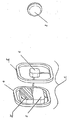
- Two transmitters present in a control and evaluation electronics unit 3 are each connected to an antenna 4 or 5 for the purpose of emitting a signal.
- the antennas 4 and 5 are designed as air coils and have the same size antenna surfaces, so that they have an approximately equal inductance.
- the antennas 4 and 5 are arranged at a small distance and aligned with their coil surfaces parallel to each other and send out alternately at their respective location in each case equally strong signal. Since with the distance from the respective antenna, the signal field strength decreases and the antennas have a (albeit small) distance from each other, an overall signal comes about, the relative field strength oscillates in the rhythm of the change of the transmitter.
- the transponder 2 is provided with means for detecting a field strength difference signal. It detects the transmission pause and subsequently detects the signal of the antenna 4 consecutively, followed by that of the antenna 5. If a transponder is located on the side of the antenna 4, then the signal of this antenna (the first signal in each case) is always greater than the signal from Antenna 5. On the side of the antenna 5, the signal of this antenna is correspondingly stronger. The transponder 2 sends back the result of this side detection to the control and evaluation electronics unit 3 on an HF link, for which purpose it is additionally provided with an HF receiver 3 '.
- the two antennas 4 and 5 are arranged at a relatively small distance from each other - the distance is typically between the radius and the diameter of the coils - affect field-distorting environmental influences, for example by metallic objects on both antennas 4, 5 in approximately the same way, so that the electromagnetic fields of both antennas are changed to the same extent. In this respect, therefore, no additional compensatory measures are required here.
- a tuning coil 6 is arranged within the coil surface of the second antenna 5, with the field strength of the two antennas 4 and 5 measured and thus at a known distance of the antennas. 4 and 5 whose field strengths can be controlled to the same value. If the distance between the two antennas 4 and 5 is not fixed exactly, for example in order to be able to take into account different installation conditions, an adjustment coil 6 must also be provided within the coil surface of the first antenna 4.
- this "left-right" detection can be extended to a universal direction detection. Due to the relative modulation deviation, which decreases with distance and is independent of the field strength of the two transmitters, the distance can be determined.
- the main advantages of the device according to the invention and the associated method are on the one hand in the higher speed, since a single transmission is sufficient to determine the position of the transponder, on the other hand allows the small distance between the antennas a very compact structure of the entire device, so that the installation costs compared to previous systems is significantly reduced. In addition, the position resolution is better than previous systems.
Landscapes
- Engineering & Computer Science (AREA)
- Radar, Positioning & Navigation (AREA)
- Remote Sensing (AREA)
- Computer Networks & Wireless Communication (AREA)
- Physics & Mathematics (AREA)
- General Physics & Mathematics (AREA)
- Radar Systems Or Details Thereof (AREA)
- Position Fixing By Use Of Radio Waves (AREA)
- Communication Control (AREA)
- Train Traffic Observation, Control, And Security (AREA)
Description
- Die vorliegende Erfindung betrifft das Gebiet der Positionsbestimmung eines Transponders. Insbesondere betrifft die Erfindung eine Einrichtung zur Positionsbestimmung eines mobilen Transponders, mit einem ortsfesten, zumindest zwei zur Abstrahlung jeweils eines Sendesignals vorgebbarer Stärke mittels dazu geeigneter Antennen vorgesehene Sender sowie eine Steuer- und Auswerteelektronikeinheit mit Mitteln zum wechselweisen Betrieb der Sender umfassenden Basissystem, und einem zur Kommunikation mit dem Basissystem vorgesehenen, mit Mitteln zur Erfassung eines Feldstärkedifferenzsignals versehen Transponder. Außerdem betrifft die Erfindung ein Verfahren zur Positionsbestimmung eines mobilen Transponders mit einem ortsfesten, zumindest zwei zur Abstrahlung jeweils eines Sendesignals vorgebbarer Stärke mittels dazu geeigneter Antennen vorgesehene Sender umfassenden Basissystem, wobei die Sendesignale von dem Transponder empfangen und in einer Feldstärkedifferenzsignal-Erfassungseinrichtung ausgewertet werden.
- Eingesetzt werden solche Einrichtungen bzw. Verfahren z.B. bei sog. Zugangsberechtigungskontrollsystemen insbesondere für Türen im Gebäudebereich, um festzustellen, ob ein sich einer Türe nähernder, als Ausweis für die Berechtigung zum Zutritt zu einem bestimmten Bereich, welcher durch die Türe von einem anderen Bereich getrennt ist, dienender Transponder der Türe von der einen oder anderen Seite nähert. Durch derartig ausgerüstete Türen werden meist Gebäudebereiche mit unterschiedlichen Zugangsberechtigungsstufen getrennt, d.h. im einfachsten Falle wird z.B. der Zutritt zu dem Gebäude insgesamt von außen geregelt. In diesem Falle ist der Türschließmechanismus meist so ausgelegt, daß die Türe von innen ohne weiteres z.B. durch Betätigung eines Tür-Drückers oder Knaufs geöffnet werden kann, während dies von der Außenseite nur dann möglich ist, wenn die Zutritt begehrende Person einen entsprechenden Berechtigungsnachweis beispielsweise in Form eines eine codierte Information beinhaltenden Transponders mit sich führt. Bei einer solchen Ausführung ist es jedoch erforderlich, dass erkannt wird, von welcher Seite sich ein solcher Transponder der Türe nähert, damit nicht bei einer Annäherung einer zutrittsberechtigten Person von der Innenseite eine unbeabsichtigte Entriegelung der Tür erfolgt, und somit ein Zugang von außen auch für nichtberechtigte Personen geschaffen ist.
- Bekannte Einrichtungen und Verfahren zur Positionsbestimmung eines Transponders insbesondere durch niederfrequente elektromagnetische Felder, d.h. also Systeme, bei denen eine Basis-Station mit Hilfe von Feldstärkeänderungen (in der Regel On-Off-Keying) zu einem mobilen Transponder hin kommuniziert, welcher wiederum durch induktive Lastmodulation des Basis-Signals zurückkommuniziert, weshalb diese Systeme auch als magnetisch gekoppelte Transpondersysteme bezeichnet werden, beruhen auf einem Prinzip, welches mittels zumindest zweier Sender arbeitet. Die zwei Sender befinden sich dabei in relativ großem Abstand zueinander (Abstand nicht wesentlich kleiner als die Größenordnung der Reichweite) und senden abwechselnd (oder gleichzeitig) ihr Signal aus. Kann der Transponder nur das Signal des ersten Senders empfangen, so befindet er sich auf der Seite dieses Senders, empfängt er nur das Signal des zweiten Senders, so befindet er sich auf dessen Seite. Kann er beide empfangen, so befindet er sich in der Mitte der beiden Sender. Variiert man nun die Sendestärke der beiden Sender, so kann die Position im Raum bestimmt werden. Sendet z.B. der erste Sender stärker und der zweite schwächer, so verschiebt sich die Zone des beiderseitigen Empfangs hin zur Seite des zweiten Senders. Abgesehen davon, dass eine Position des Transponders außerhalb der Verbindungslinie der beiden Sender hierbei nur sehr ungenau bestimmt werden kann, hat diese bekannte Vorgehensweise noch weitere erhebliche Nachteile. So müssen beispielsweise für jede einzelne Positionsbestimmung mehrere Sendevorgänge mit verschiedenen Feldstärken durchgeführt und jeweils die Rückantwort des Transponders abgewartet werden. Je genauer die Positionsbestimmung durchgeführt werden soll, desto mehr Sendevorgänge sind notwendig, was das Verfahren zeitaufwendig macht. Außerdem müssen die Antennen in relativ großer Entfernung zueinander aufgestellt und relativ zueinander ausgerichtet sein bzw. nach der Installation vermessen werden; bei einer Sende-Reichweite von ca. 2 Metern zu beiden Seiten eines Bezugspunktes müssen die Antennen mindestens etwa 0,5 Meter auseinander stehen, um ein befriedigendes Ergebnis zu erzielen. Damit die Positionsentfernung korrekt ist, müssen die beiden Sender einen definierten, gleichbleibenden Signalpegel erzeugen, was bei den zur Realisierung solcher Systeme eingesetzten Schwingkreisen mit typischen Güten zwischen 20-60 wegen der möglichen Verstimmung etwa durch Temperaturdrift einen erhöhten Aufwand erforderlich macht.
- Die
DE 100 32 936 A1 offenbart eine Einrichtung gemäß dem Oberbegriff des Patentanspruchs 1. Bei dieser zum Steuern einer Zugangsberechtigung und/oder einer elektronischen Wegfahrsperre für ein Kraftfahrzeug vorgesehenen Einrichtung sind zwei Antennen auf den einander gegenüberliegenden Seiten des Kraftfahrzeugs, und damit in einem Abstand von etwa einem Meter zueinander angeordnet. Durch diesen großen Abstand ist bei in etwa gleich großer von den jeweiligen Antennen abgestrahlter Signalstärke ein deutlicher Unterschied der empfangenen Feldstärke am Ort des Transponders festzustellen. Zur Unterscheidung der beiden Antennen durch den Transponder wird den Sendesignalen eine charakteristische Kennung hinzugefügt, die im Transponder zusätzlich ausgewertet werden muss. Aufgrund des erforderlichen, relativ großen Abstandes der Antennen zueinander eignet sich diese Einrichtung nicht zum Einsatz bei den eingangs beschriebenen Zugangsberechtigungskontrollsystemen für Türen im Gebäudebereich, um festzustellen, ob ein sich einer Türe nähernder, als Ausweis für die Berechtigung zum Zutritt zu einem bestimmten Bereich, welcher durch die Türe von einem anderen Bereich getrennt ist, dienender Transponder der Türe von der einen oder anderen Seite nähert. - Aufgabe der vorliegenden Erfindung ist es deshalb, eine Einrichtung zu schaffen sowie ein Verfahren anzugeben, welche die geschilderten Nachteile des Standes der Technik überwinden und sich zudem für den Einsatz im Gebäudebereich besonders eignen.
- Dies gelingt der erfindungsgemäßen Einrichtung dadurch, dass die Antennen der Sender als Luftspulen mit etwa gleich großen Antennenflächen ausgebildet sind, die mit ihren Spulenflächen parallel zueinander ausgerichtet angeordnet sind, wobei ihr Abstand zueinander größer als der Spulenradius und geringer als der Spulendurchmesser ist.
- Die verfahrensbezogene Aufgabe wird dadurch gelöst, dass die Sender wechselweise jeweils ein- und ausgeschaltet werden, um über ihre Antennen jeweils ein Signal gleicher Stärke am jeweiligen Antennenort abzustrahlen, wobei in festgelegten Zeitabständen eine Sendepause erfolgt, nach der stets mit der Aussendung des Signals eines festgelegten der beiden Sender begonnen wird.
- Weitere vorteilhafte Ausgestaltungen des erfindungsgemäßen Gegenstandes sind in den weiteren Unteransprüchen angegeben und werden anhand des in der Zeichnung dargestellten Ausführungsbeispiels näher erläutert.
- Zwei in einer Steuer- und Auswerteelektronikeinheit 3 vorhandene Sender sind jeweils mit einer Antenne 4 bzw. 5 zur Abstrahlung eines Signals verbunden. Die Antennen 4 und 5 sind als Luftspulen ausgebildet und weisen gleich große Antennenflächen auf, so dass sie eine etwa gleich große Induktivität besitzen. Die Antennen 4 und 5 sind in geringer Entfernung und mit ihren Spulenflächen parallel zueinander ausgerichtet angeordnet und senden abwechselnd ein an ihrem jeweiligen Ort jeweils gleich starkes Signal aus. Da mit der Entfernung von der jeweiligen Antenne die Signalfeldstärke abnimmt und die Antennen eine (wenn auch geringe) Distanz zueinander aufweisen, kommt ein Gesamt-Signal zustande, dessen relative Feldstärke im Rhythmus des Wechsels der Sender oszilliert. Besonders im Nahfeld der elektromagnetischen Welle (Entfernung zur Antenne < λ/8) kommt es zu einer deutlich messbaren Modulation, da hier die Feldstärke mit 60dB pro Dekade Entfernung abnimmt. Damit eine Identifizierung möglich ist, ob das jeweilige Signal von Antenne 4 oder Antenne 5 herrührt, wird in definierten Abständen eine Sendepause durchgeführt (kein Signal) und nach dieser Pause stets mit dem Signal des der Antenne 4 zugeordneten Senders angefangen.
- Der Transponder 2 ist mit Mitteln zur Erfassung eines Feldstärkedifferenzsignals versehen. Er erkennt die Sendepause und detektiert anschließend nacheinander das Signal der Antenne 4, gefolgt von dem der Antenne 5. Befindet sich ein Transponder auf der Seite der Antenne 4, so ist das Signal dieser Antenne (das jeweils erste Signal) stets größer als das Signal von Antenne 5. Auf der Seite der Antenne 5 ist dann dementsprechend das Signal dieser Antenne stärker. Der Transponder 2 sendet auf einer HF-Strecke das Ergebnis dieser Seitenerfassung an die Steuer- und Auswerteelektronikeinheit 3 zurück, wozu diese zusätzlich mit einem HF-Empfangsteil 3' versehen ist.
- Da die beiden Antennen 4 und 5 in relativ geringem Abstand zueinander angeordnet sind - der Abstand liegt typischerweise zwischen dem Radius und dem Durchmesser der Spulen - wirken feldverzerrende Umgebungseinflüsse, z.B. durch metallische Gegenstände, auf beide Antennen 4, 5 in etwa gleicher Weise, so dass die elektromagnetischen Felder beider Antennen im gleichen Maße verändert werden. In dieser Hinsicht sind hier deshalb keine zusätzlichen Ausgleichsmaßnahmen erforderlich. Um einen Ausgleich auch weiterer Fehlereinflüsse wie z.B. ein unterschiedliches Driften der beiden Sender kompensieren zu können, ist innerhalb der Spulenfläche der zweiten Antenne 5 eine Abgleichspule 6 angeordnet, mit der die Feldstärke der beiden Antennen 4 und 5 gemessen und somit bei bekanntem Abstand der Antennen 4 und 5 deren Feldstärken auf den gleichen Wert geregelt werden können. Falls der Abstand der beiden Antennen 4 und 5 nicht genau festliegt, z.B. um unterschiedliche Einbaubedingungen berücksichtigen zu können, so ist auch innerhalb der Spulenfläche der ersten Antenne 4 eine Abgleichspule 6 vorzusehen.
- Durch den Einsatz von zumindest drei Sendern kann diese "Links-Rechts"-Erkennung zu einer universellen Richtungserkennung erweitert werden. Durch den relativen Modulationshub, welcher mit der Entfernung abnimmt und von der Feldstärke der beiden Sender unabhängig ist, kann die Entfernung ermittelt werden. Die wesentlichen Vorteile der erfindungsgemäßen Einrichtung sowie des zugehörigen Verfahrens liegen zum einen in der höheren Geschwindigkeit, da ein einmaliger Sendevorgang ausreicht, um die Position des Transponders zu bestimmen, zum anderen erlaubt der geringe Abstand zwischen den Antennen einen sehr kompakten Aufbau der gesamten Einrichtung, so dass der Installationsaufwand gegenüber bisherigen Systemen deutlich verringert ist. Zudem ist die Positionsauflösung besser als bei bisherigen Systemen.
Claims (6)
- Einrichtung zur Positionsbestimmung eines mobilen Transponders (2), mit einem ortsfesten, zumindest zwei zur Abstrahlung jeweils eines Sendesignals vorgebbarer Stärke mittels dazu geeigneter Antennen (4, 5) vorgesehene Sender sowie eine Steuer- und Auswerteelektronikeinheit (3) mit Mitteln zum wechselweisen Betrieb der Sender umfassenden Basissystem (1), und einem zur Kommunikation mit dem Basissystem (1) vorgesehenen, mit Mitteln zur Erfassung eines Feldstärkedifferenzsignals versehen Transponder (2), dadurch gekennzeichnet, dass die Antennen (4, 5) der Sender als Luftspulen mit etwa gleich großen Antennenflächen ausgebildet sind, die mit ihren Spulenflächen parallel zueinander ausgerichtet angeordnet sind, wobei ihr Abstand zueinander größer als der Spulenradius und geringer als der Spulendurchmesser ist.
- Einrichtung nach Anspruch 1, dadurch gekennzeichnet, dass es sich bei den von den Sendern abgestrahlten Sendesignalen um niederfrequente elektromagnetische Felder handelt.
- Einrichtung nach Anspruch 1 oder 2, dadurch gekennzeichnet, dass innerhalb der Spulenfläche zumindest einer Antenne (4, 5) eine Abgleichspule (6) zum Messen der Feldstärke angeordnet ist.
- Einrichtung nach einem der Ansprüche 1 bis 3, dadurch gekennzeichnet, dass der Transponder (2) einen HF-Sender und die Basiseinheit (1) eine HF-Empfangseinrichtung (3') zur Rückkommunikation umfassen.
- Verfahren zur Positionsbestimmung eines mobilen Transponders (2) mit einer Einrichtung gemäß einem der Ansprüche 1 bis 4, dadurch gekennzeichnet, dass die Sender wechselweise jeweils ein- und ausgeschaltet werden, um über ihre Antennen (4, 5) jeweils ein Signal gleicher Stärke am jeweiligen Antennenort abzustrahlen, wobei in festgelegten Zeitabständen eine Sendepause erfolgt, nach der stets mit der Aussendung des Signals eines festgelegten der beiden Sender begonnen wird.
- Verfahren nach Anspruch 5, dadurch gekennzeichnet, dass das Ergebnis der Positionsbestimmung über eine HF-Strecke an die Basisstation (1) zurückgesendet wird.
Applications Claiming Priority (3)
| Application Number | Priority Date | Filing Date | Title |
|---|---|---|---|
| DE10237605 | 2002-08-16 | ||
| DE10237605A DE10237605A1 (de) | 2002-08-16 | 2002-08-16 | Einrichtung und Verfahren zur Positionsbestimmung eines Transponders |
| PCT/EP2003/008980 WO2004077087A2 (de) | 2002-08-16 | 2003-08-13 | Einrichtung und verfahren zur positionsbestimmung eines transponders |
Publications (2)
| Publication Number | Publication Date |
|---|---|
| EP1529222A2 EP1529222A2 (de) | 2005-05-11 |
| EP1529222B1 true EP1529222B1 (de) | 2010-09-15 |
Family
ID=31197045
Family Applications (1)
| Application Number | Title | Priority Date | Filing Date |
|---|---|---|---|
| EP03815795A Expired - Lifetime EP1529222B1 (de) | 2002-08-16 | 2003-08-13 | Einrichtung und verfahren zur positionsbestimmung eines transponders |
Country Status (5)
| Country | Link |
|---|---|
| EP (1) | EP1529222B1 (de) |
| AT (1) | ATE481649T1 (de) |
| AU (1) | AU2003303738A1 (de) |
| DE (2) | DE10237605A1 (de) |
| WO (1) | WO2004077087A2 (de) |
Families Citing this family (3)
| Publication number | Priority date | Publication date | Assignee | Title |
|---|---|---|---|---|
| DE102007006182A1 (de) * | 2007-02-07 | 2008-08-21 | Siemens Ag | Verfahren, Vorrichtung und Anordnung zur Positionsbestimmung eines ID-Gebers |
| DE102008047577B3 (de) | 2008-09-17 | 2010-08-12 | Siemens Medical Instruments Pte. Ltd. | Rechts-Links-Erkennung bei Hörhilfegeräten |
| EP2367021A1 (de) | 2010-03-17 | 2011-09-21 | The Swatch Group Research and Development Ltd. | Verfahren und System zur Lokalisierung von Objekten |
Family Cites Families (4)
| Publication number | Priority date | Publication date | Assignee | Title |
|---|---|---|---|---|
| DE19802532C1 (de) * | 1998-01-26 | 1999-08-12 | Bosch Gmbh Robert | Verfahren zum Betreiben eines schlüssellosen Zutrittsystems eines Fahrzeugs |
| DE10013542A1 (de) * | 2000-03-20 | 2001-09-27 | Philips Corp Intellectual Pty | Anordnung für ein Zugangssicherungssystem ("Passive Keyless Entry System") |
| DE10032936A1 (de) * | 2000-07-06 | 2002-02-07 | Siemens Ag | Vorrichtung und Verfahren zum Steuern einer Zugangsberechtigung und/oder einer elektronischen Wegfahrsperre für ein Kraftfahrzeug |
| DE10045776C2 (de) * | 2000-09-15 | 2003-08-14 | Siemens Ag | Verfahren zum Bestimmen der Position eines Objekts und Verfahren zum Steuern eines Zugangs zu einem Objekt oder einer Benutzung des Objekts, insbesondere eines Kraftfahrzeugs |
-
2002
- 2002-08-16 DE DE10237605A patent/DE10237605A1/de not_active Withdrawn
-
2003
- 2003-08-13 AU AU2003303738A patent/AU2003303738A1/en not_active Abandoned
- 2003-08-13 DE DE50313100T patent/DE50313100D1/de not_active Expired - Lifetime
- 2003-08-13 AT AT03815795T patent/ATE481649T1/de active
- 2003-08-13 EP EP03815795A patent/EP1529222B1/de not_active Expired - Lifetime
- 2003-08-13 WO PCT/EP2003/008980 patent/WO2004077087A2/de not_active Ceased
Also Published As
| Publication number | Publication date |
|---|---|
| DE10237605A1 (de) | 2004-03-04 |
| WO2004077087A3 (de) | 2004-11-25 |
| WO2004077087A2 (de) | 2004-09-10 |
| EP1529222A2 (de) | 2005-05-11 |
| DE50313100D1 (de) | 2010-10-28 |
| AU2003303738A1 (en) | 2004-09-17 |
| ATE481649T1 (de) | 2010-10-15 |
| AU2003303738A8 (en) | 2004-09-17 |
Similar Documents
| Publication | Publication Date | Title |
|---|---|---|
| DE10212648B4 (de) | Identifikationssystem zum Nachweis einer Berechtigung für den Zugang zu einem Objekt oder die Benutzung eines Objekts, insbesondere eines Kraftfahrzeugs | |
| EP1861808B1 (de) | Datenübertragungsverfahren und rfid-lesegerät mit spule und regelschaltung zur feldauslöschung ausserhalb des kommunikationsbereiches | |
| EP1318483B1 (de) | Verfahren zur Erkennung einer Weiterleitung bei einer kontaktlosen Datenübertragung | |
| EP2782775B1 (de) | System zur positionsbestimmung von zueinander beweglichen objekten | |
| DE102016223252B4 (de) | Zugangsvorrichtung für ein Fahrzeug | |
| DE10013542A1 (de) | Anordnung für ein Zugangssicherungssystem ("Passive Keyless Entry System") | |
| EP2125449B1 (de) | Verfahren zur abstandscharakterisierung bei induktiv gekoppelten zugangssystemen für fahrzeuge | |
| DE19845649B4 (de) | Schlüssellose Zugangs- und/oder Fahrberechtigungskontrolleinrichtung für ein Kraftfahrzeug | |
| DE10032936A1 (de) | Vorrichtung und Verfahren zum Steuern einer Zugangsberechtigung und/oder einer elektronischen Wegfahrsperre für ein Kraftfahrzeug | |
| EP1990755A1 (de) | Verfahren zum Betrieb eins RFID-Tags mit genauer Lokalisierung | |
| EP3864427B1 (de) | Vorrichtung zur positionsbestimmung eines relativ zu einem fahrzeug bewegbaren gegenstandes und ein damit ausgestattetes fahrzeug | |
| EP3350015A1 (de) | Verfahren zur ermittlung einer eine relativposition eines kraftfahrzeugs zu einer stationären, anzufahrenden ladeeinrichtung beschreibenden positionsinformation und anordnung aus einem kraftfahrzeug und einer stationären, anzufahrenden ladeeinrichtung | |
| EP1506432A1 (de) | Sensor zum aussenden und empfangen von elektromagnetischen signalen | |
| DE102017200668B4 (de) | Verfahren zur Absicherung eines Zugangs | |
| DE10046897B4 (de) | Sende- und Empfangsverfahren, insbesondere zum Detektieren eines ID-Gebers | |
| EP3640896B1 (de) | Fahrzeugtürgriff mit nahfeld-kommunikationselektronik | |
| EP1083280B1 (de) | Schlüssellose Betätigungs- und/oder Schliesseinrichtung für insbesondere Kraftfahrzeuge | |
| DE19839478A1 (de) | Zugangs- und Start/Fahrberechtigungssystem für ein Kraftfahrzeug | |
| EP1529222A2 (de) | Einrichtung und verfahren zur positionsbestimmung eines transponders | |
| DE102004036258B4 (de) | Verfahren und Vorrichtung zur Lokalisierung einer als ID-Geber, insbesondere Fahrzeugschlüssel, ausgebildeten mobilen Sendeeinrichtung | |
| DE10151034B4 (de) | Diebstahlschutzsystem, Verfahren zum Betreiben eines Diebstahlschutzsystems und Komponenten eines Diebstahlschutzsystems | |
| DE102007006466B4 (de) | Verfahren zur Positionserkennung eines ID-Gebers in einem Keyless-Entry-Go-System | |
| DE102004038837B4 (de) | Elektronisches Diebstahlschutzsystem mit korrelierten Sende-/Empfangsantennen | |
| DE102004036837B4 (de) | Selbstreinigende Abluftkammer und Reinigungssystem für eine Abluftkammer | |
| DE102004061478A1 (de) | Datenübertragungsverfahren und RFID-Lesegerät |
Legal Events
| Date | Code | Title | Description |
|---|---|---|---|
| PUAI | Public reference made under article 153(3) epc to a published international application that has entered the european phase |
Free format text: ORIGINAL CODE: 0009012 |
|
| 17P | Request for examination filed |
Effective date: 20050202 |
|
| AK | Designated contracting states |
Kind code of ref document: A2 Designated state(s): AT BE BG CH CY CZ DE DK EE ES FI FR GB GR HU IE IT LI LU MC NL PT RO SE SI SK TR |
|
| AX | Request for extension of the european patent |
Extension state: AL LT LV MK |
|
| DAX | Request for extension of the european patent (deleted) | ||
| RIN1 | Information on inventor provided before grant (corrected) |
Inventor name: WUSTLICH, ANDRE Inventor name: RICKHOFF, DIETER Inventor name: TRABERT, JOERG Inventor name: DEGENER, MARTIN |
|
| 17Q | First examination report despatched |
Effective date: 20070402 |
|
| R17C | First examination report despatched (corrected) |
Effective date: 20070801 |
|
| GRAP | Despatch of communication of intention to grant a patent |
Free format text: ORIGINAL CODE: EPIDOSNIGR1 |
|
| GRAS | Grant fee paid |
Free format text: ORIGINAL CODE: EPIDOSNIGR3 |
|
| GRAA | (expected) grant |
Free format text: ORIGINAL CODE: 0009210 |
|
| AK | Designated contracting states |
Kind code of ref document: B1 Designated state(s): AT BE BG CH CY CZ DE DK EE ES FI FR GB GR HU IE IT LI LU MC NL PT RO SE SI SK TR |
|
| REG | Reference to a national code |
Ref country code: GB Ref legal event code: FG4D Free format text: NOT ENGLISH Ref country code: CH Ref legal event code: EP |
|
| REG | Reference to a national code |
Ref country code: IE Ref legal event code: FG4D Free format text: LANGUAGE OF EP DOCUMENT: GERMAN |
|
| REF | Corresponds to: |
Ref document number: 50313100 Country of ref document: DE Date of ref document: 20101028 Kind code of ref document: P |
|
| REG | Reference to a national code |
Ref country code: NL Ref legal event code: VDEP Effective date: 20100915 |
|
| PG25 | Lapsed in a contracting state [announced via postgrant information from national office to epo] |
Ref country code: FI Free format text: LAPSE BECAUSE OF FAILURE TO SUBMIT A TRANSLATION OF THE DESCRIPTION OR TO PAY THE FEE WITHIN THE PRESCRIBED TIME-LIMIT Effective date: 20100915 |
|
| PG25 | Lapsed in a contracting state [announced via postgrant information from national office to epo] |
Ref country code: SI Free format text: LAPSE BECAUSE OF FAILURE TO SUBMIT A TRANSLATION OF THE DESCRIPTION OR TO PAY THE FEE WITHIN THE PRESCRIBED TIME-LIMIT Effective date: 20100915 Ref country code: CY Free format text: LAPSE BECAUSE OF FAILURE TO SUBMIT A TRANSLATION OF THE DESCRIPTION OR TO PAY THE FEE WITHIN THE PRESCRIBED TIME-LIMIT Effective date: 20100915 |
|
| PG25 | Lapsed in a contracting state [announced via postgrant information from national office to epo] |
Ref country code: SE Free format text: LAPSE BECAUSE OF FAILURE TO SUBMIT A TRANSLATION OF THE DESCRIPTION OR TO PAY THE FEE WITHIN THE PRESCRIBED TIME-LIMIT Effective date: 20100915 Ref country code: GR Free format text: LAPSE BECAUSE OF FAILURE TO SUBMIT A TRANSLATION OF THE DESCRIPTION OR TO PAY THE FEE WITHIN THE PRESCRIBED TIME-LIMIT Effective date: 20101216 |
|
| REG | Reference to a national code |
Ref country code: IE Ref legal event code: FD4D |
|
| PG25 | Lapsed in a contracting state [announced via postgrant information from national office to epo] |
Ref country code: IE Free format text: LAPSE BECAUSE OF FAILURE TO SUBMIT A TRANSLATION OF THE DESCRIPTION OR TO PAY THE FEE WITHIN THE PRESCRIBED TIME-LIMIT Effective date: 20100915 |
|
| PG25 | Lapsed in a contracting state [announced via postgrant information from national office to epo] |
Ref country code: NL Free format text: LAPSE BECAUSE OF FAILURE TO SUBMIT A TRANSLATION OF THE DESCRIPTION OR TO PAY THE FEE WITHIN THE PRESCRIBED TIME-LIMIT Effective date: 20100915 Ref country code: SK Free format text: LAPSE BECAUSE OF FAILURE TO SUBMIT A TRANSLATION OF THE DESCRIPTION OR TO PAY THE FEE WITHIN THE PRESCRIBED TIME-LIMIT Effective date: 20100915 Ref country code: EE Free format text: LAPSE BECAUSE OF FAILURE TO SUBMIT A TRANSLATION OF THE DESCRIPTION OR TO PAY THE FEE WITHIN THE PRESCRIBED TIME-LIMIT Effective date: 20100915 Ref country code: IT Free format text: LAPSE BECAUSE OF FAILURE TO SUBMIT A TRANSLATION OF THE DESCRIPTION OR TO PAY THE FEE WITHIN THE PRESCRIBED TIME-LIMIT Effective date: 20100915 Ref country code: PT Free format text: LAPSE BECAUSE OF FAILURE TO SUBMIT A TRANSLATION OF THE DESCRIPTION OR TO PAY THE FEE WITHIN THE PRESCRIBED TIME-LIMIT Effective date: 20110117 Ref country code: RO Free format text: LAPSE BECAUSE OF FAILURE TO SUBMIT A TRANSLATION OF THE DESCRIPTION OR TO PAY THE FEE WITHIN THE PRESCRIBED TIME-LIMIT Effective date: 20100915 Ref country code: CZ Free format text: LAPSE BECAUSE OF FAILURE TO SUBMIT A TRANSLATION OF THE DESCRIPTION OR TO PAY THE FEE WITHIN THE PRESCRIBED TIME-LIMIT Effective date: 20100915 |
|
| PG25 | Lapsed in a contracting state [announced via postgrant information from national office to epo] |
Ref country code: ES Free format text: LAPSE BECAUSE OF FAILURE TO SUBMIT A TRANSLATION OF THE DESCRIPTION OR TO PAY THE FEE WITHIN THE PRESCRIBED TIME-LIMIT Effective date: 20101226 |
|
| PLBE | No opposition filed within time limit |
Free format text: ORIGINAL CODE: 0009261 |
|
| STAA | Information on the status of an ep patent application or granted ep patent |
Free format text: STATUS: NO OPPOSITION FILED WITHIN TIME LIMIT |
|
| 26N | No opposition filed |
Effective date: 20110616 |
|
| PG25 | Lapsed in a contracting state [announced via postgrant information from national office to epo] |
Ref country code: DK Free format text: LAPSE BECAUSE OF FAILURE TO SUBMIT A TRANSLATION OF THE DESCRIPTION OR TO PAY THE FEE WITHIN THE PRESCRIBED TIME-LIMIT Effective date: 20100915 |
|
| REG | Reference to a national code |
Ref country code: DE Ref legal event code: R097 Ref document number: 50313100 Country of ref document: DE Effective date: 20110616 |
|
| BERE | Be: lapsed |
Owner name: LEOPOLD KOSTAL G.M.B.H. & CO. KG Effective date: 20110831 |
|
| PG25 | Lapsed in a contracting state [announced via postgrant information from national office to epo] |
Ref country code: MC Free format text: LAPSE BECAUSE OF NON-PAYMENT OF DUE FEES Effective date: 20110831 |
|
| REG | Reference to a national code |
Ref country code: CH Ref legal event code: PL |
|
| GBPC | Gb: european patent ceased through non-payment of renewal fee |
Effective date: 20110813 |
|
| PG25 | Lapsed in a contracting state [announced via postgrant information from national office to epo] |
Ref country code: LI Free format text: LAPSE BECAUSE OF NON-PAYMENT OF DUE FEES Effective date: 20110831 Ref country code: CH Free format text: LAPSE BECAUSE OF NON-PAYMENT OF DUE FEES Effective date: 20110831 |
|
| REG | Reference to a national code |
Ref country code: FR Ref legal event code: ST Effective date: 20120430 |
|
| PG25 | Lapsed in a contracting state [announced via postgrant information from national office to epo] |
Ref country code: BE Free format text: LAPSE BECAUSE OF NON-PAYMENT OF DUE FEES Effective date: 20110831 |
|
| PG25 | Lapsed in a contracting state [announced via postgrant information from national office to epo] |
Ref country code: GB Free format text: LAPSE BECAUSE OF NON-PAYMENT OF DUE FEES Effective date: 20110813 Ref country code: FR Free format text: LAPSE BECAUSE OF NON-PAYMENT OF DUE FEES Effective date: 20110831 |
|
| REG | Reference to a national code |
Ref country code: AT Ref legal event code: MM01 Ref document number: 481649 Country of ref document: AT Kind code of ref document: T Effective date: 20110813 |
|
| PG25 | Lapsed in a contracting state [announced via postgrant information from national office to epo] |
Ref country code: AT Free format text: LAPSE BECAUSE OF NON-PAYMENT OF DUE FEES Effective date: 20110813 |
|
| PG25 | Lapsed in a contracting state [announced via postgrant information from national office to epo] |
Ref country code: LU Free format text: LAPSE BECAUSE OF NON-PAYMENT OF DUE FEES Effective date: 20110813 |
|
| PG25 | Lapsed in a contracting state [announced via postgrant information from national office to epo] |
Ref country code: BG Free format text: LAPSE BECAUSE OF FAILURE TO SUBMIT A TRANSLATION OF THE DESCRIPTION OR TO PAY THE FEE WITHIN THE PRESCRIBED TIME-LIMIT Effective date: 20101215 Ref country code: TR Free format text: LAPSE BECAUSE OF FAILURE TO SUBMIT A TRANSLATION OF THE DESCRIPTION OR TO PAY THE FEE WITHIN THE PRESCRIBED TIME-LIMIT Effective date: 20100915 |
|
| PG25 | Lapsed in a contracting state [announced via postgrant information from national office to epo] |
Ref country code: HU Free format text: LAPSE BECAUSE OF FAILURE TO SUBMIT A TRANSLATION OF THE DESCRIPTION OR TO PAY THE FEE WITHIN THE PRESCRIBED TIME-LIMIT Effective date: 20100915 |
|
| REG | Reference to a national code |
Ref country code: DE Ref legal event code: R084 Ref document number: 50313100 Country of ref document: DE |
|
| REG | Reference to a national code |
Ref country code: DE Ref legal event code: R081 Ref document number: 50313100 Country of ref document: DE Owner name: KOSTAL AUTOMOBIL ELEKTRIK GMBH & CO. KG, DE Free format text: FORMER OWNER: LEOPOLD KOSTAL GMBH & CO. KG, 58513 LUEDENSCHEID, DE |
|
| PGFP | Annual fee paid to national office [announced via postgrant information from national office to epo] |
Ref country code: DE Payment date: 20210907 Year of fee payment: 19 |
|
| REG | Reference to a national code |
Ref country code: DE Ref legal event code: R119 Ref document number: 50313100 Country of ref document: DE |
|
| PG25 | Lapsed in a contracting state [announced via postgrant information from national office to epo] |
Ref country code: DE Free format text: LAPSE BECAUSE OF NON-PAYMENT OF DUE FEES Effective date: 20230301 |