EP1528989B1 - Systeme et procede pour maintenir le niveau d'un plan utile d'un vehicule - Google Patents
Systeme et procede pour maintenir le niveau d'un plan utile d'un vehicule Download PDFInfo
- Publication number
- EP1528989B1 EP1528989B1 EP03784138A EP03784138A EP1528989B1 EP 1528989 B1 EP1528989 B1 EP 1528989B1 EP 03784138 A EP03784138 A EP 03784138A EP 03784138 A EP03784138 A EP 03784138A EP 1528989 B1 EP1528989 B1 EP 1528989B1
- Authority
- EP
- European Patent Office
- Prior art keywords
- hydraulic cylinder
- operating state
- valve
- state
- switching
- Prior art date
- Legal status (The legal status is an assumption and is not a legal conclusion. Google has not performed a legal analysis and makes no representation as to the accuracy of the status listed.)
- Expired - Lifetime
Links
- 238000000034 method Methods 0.000 title claims abstract description 33
- 239000000725 suspension Substances 0.000 claims description 20
- 239000006096 absorbing agent Substances 0.000 claims description 10
- 230000035939 shock Effects 0.000 claims description 10
- 230000004044 response Effects 0.000 claims description 8
- 230000008878 coupling Effects 0.000 claims description 4
- 238000010168 coupling process Methods 0.000 claims description 4
- 238000005859 coupling reaction Methods 0.000 claims description 4
- 239000012530 fluid Substances 0.000 claims description 3
- 230000000740 bleeding effect Effects 0.000 claims 6
- 238000005273 aeration Methods 0.000 claims 3
- 238000013022 venting Methods 0.000 abstract description 12
- 230000006870 function Effects 0.000 description 11
- 238000012546 transfer Methods 0.000 description 6
- 238000009423 ventilation Methods 0.000 description 3
- 238000013459 approach Methods 0.000 description 2
- 230000008901 benefit Effects 0.000 description 2
- 230000008859 change Effects 0.000 description 2
- 238000004891 communication Methods 0.000 description 2
- 230000006835 compression Effects 0.000 description 2
- 238000007906 compression Methods 0.000 description 2
- 230000007423 decrease Effects 0.000 description 2
- 230000009977 dual effect Effects 0.000 description 2
- 210000003746 feather Anatomy 0.000 description 2
- 230000008569 process Effects 0.000 description 2
- 230000001419 dependent effect Effects 0.000 description 1
- 238000013461 design Methods 0.000 description 1
- 238000001514 detection method Methods 0.000 description 1
- 238000006073 displacement reaction Methods 0.000 description 1
- 230000001105 regulatory effect Effects 0.000 description 1
- 230000035945 sensitivity Effects 0.000 description 1
Images

Classifications
-
- B—PERFORMING OPERATIONS; TRANSPORTING
- B60—VEHICLES IN GENERAL
- B60G—VEHICLE SUSPENSION ARRANGEMENTS
- B60G15/00—Resilient suspensions characterised by arrangement, location or type of combined spring and vibration damper, e.g. telescopic type
- B60G15/08—Resilient suspensions characterised by arrangement, location or type of combined spring and vibration damper, e.g. telescopic type having fluid spring
- B60G15/12—Resilient suspensions characterised by arrangement, location or type of combined spring and vibration damper, e.g. telescopic type having fluid spring and fluid damper
-
- B—PERFORMING OPERATIONS; TRANSPORTING
- B60—VEHICLES IN GENERAL
- B60G—VEHICLE SUSPENSION ARRANGEMENTS
- B60G17/00—Resilient suspensions having means for adjusting the spring or vibration-damper characteristics, for regulating the distance between a supporting surface and a sprung part of vehicle or for locking suspension during use to meet varying vehicular or surface conditions, e.g. due to speed or load
- B60G17/005—Suspension locking arrangements
-
- B—PERFORMING OPERATIONS; TRANSPORTING
- B60—VEHICLES IN GENERAL
- B60G—VEHICLE SUSPENSION ARRANGEMENTS
- B60G17/00—Resilient suspensions having means for adjusting the spring or vibration-damper characteristics, for regulating the distance between a supporting surface and a sprung part of vehicle or for locking suspension during use to meet varying vehicular or surface conditions, e.g. due to speed or load
- B60G17/015—Resilient suspensions having means for adjusting the spring or vibration-damper characteristics, for regulating the distance between a supporting surface and a sprung part of vehicle or for locking suspension during use to meet varying vehicular or surface conditions, e.g. due to speed or load the regulating means comprising electric or electronic elements
- B60G17/0152—Resilient suspensions having means for adjusting the spring or vibration-damper characteristics, for regulating the distance between a supporting surface and a sprung part of vehicle or for locking suspension during use to meet varying vehicular or surface conditions, e.g. due to speed or load the regulating means comprising electric or electronic elements characterised by the action on a particular type of suspension unit
- B60G17/0155—Resilient suspensions having means for adjusting the spring or vibration-damper characteristics, for regulating the distance between a supporting surface and a sprung part of vehicle or for locking suspension during use to meet varying vehicular or surface conditions, e.g. due to speed or load the regulating means comprising electric or electronic elements characterised by the action on a particular type of suspension unit pneumatic unit
-
- B—PERFORMING OPERATIONS; TRANSPORTING
- B60—VEHICLES IN GENERAL
- B60G—VEHICLE SUSPENSION ARRANGEMENTS
- B60G17/00—Resilient suspensions having means for adjusting the spring or vibration-damper characteristics, for regulating the distance between a supporting surface and a sprung part of vehicle or for locking suspension during use to meet varying vehicular or surface conditions, e.g. due to speed or load
- B60G17/015—Resilient suspensions having means for adjusting the spring or vibration-damper characteristics, for regulating the distance between a supporting surface and a sprung part of vehicle or for locking suspension during use to meet varying vehicular or surface conditions, e.g. due to speed or load the regulating means comprising electric or electronic elements
- B60G17/017—Resilient suspensions having means for adjusting the spring or vibration-damper characteristics, for regulating the distance between a supporting surface and a sprung part of vehicle or for locking suspension during use to meet varying vehicular or surface conditions, e.g. due to speed or load the regulating means comprising electric or electronic elements characterised by their use when the vehicle is stationary, e.g. during loading, engine start-up or switch-off
-
- B—PERFORMING OPERATIONS; TRANSPORTING
- B60—VEHICLES IN GENERAL
- B60G—VEHICLE SUSPENSION ARRANGEMENTS
- B60G17/00—Resilient suspensions having means for adjusting the spring or vibration-damper characteristics, for regulating the distance between a supporting surface and a sprung part of vehicle or for locking suspension during use to meet varying vehicular or surface conditions, e.g. due to speed or load
- B60G17/02—Spring characteristics, e.g. mechanical springs and mechanical adjusting means
- B60G17/04—Spring characteristics, e.g. mechanical springs and mechanical adjusting means fluid spring characteristics
- B60G17/052—Pneumatic spring characteristics
- B60G17/0523—Regulating distributors or valves for pneumatic springs
-
- B—PERFORMING OPERATIONS; TRANSPORTING
- B60—VEHICLES IN GENERAL
- B60G—VEHICLE SUSPENSION ARRANGEMENTS
- B60G17/00—Resilient suspensions having means for adjusting the spring or vibration-damper characteristics, for regulating the distance between a supporting surface and a sprung part of vehicle or for locking suspension during use to meet varying vehicular or surface conditions, e.g. due to speed or load
- B60G17/02—Spring characteristics, e.g. mechanical springs and mechanical adjusting means
- B60G17/04—Spring characteristics, e.g. mechanical springs and mechanical adjusting means fluid spring characteristics
- B60G17/052—Pneumatic spring characteristics
- B60G17/0523—Regulating distributors or valves for pneumatic springs
- B60G17/0525—Height adjusting or levelling valves
-
- B—PERFORMING OPERATIONS; TRANSPORTING
- B60—VEHICLES IN GENERAL
- B60G—VEHICLE SUSPENSION ARRANGEMENTS
- B60G2202/00—Indexing codes relating to the type of spring, damper or actuator
- B60G2202/10—Type of spring
- B60G2202/15—Fluid spring
- B60G2202/152—Pneumatic spring
-
- B—PERFORMING OPERATIONS; TRANSPORTING
- B60—VEHICLES IN GENERAL
- B60G—VEHICLE SUSPENSION ARRANGEMENTS
- B60G2202/00—Indexing codes relating to the type of spring, damper or actuator
- B60G2202/20—Type of damper
- B60G2202/24—Fluid damper
-
- B—PERFORMING OPERATIONS; TRANSPORTING
- B60—VEHICLES IN GENERAL
- B60G—VEHICLE SUSPENSION ARRANGEMENTS
- B60G2202/00—Indexing codes relating to the type of spring, damper or actuator
- B60G2202/30—Spring/Damper and/or actuator Units
-
- B—PERFORMING OPERATIONS; TRANSPORTING
- B60—VEHICLES IN GENERAL
- B60G—VEHICLE SUSPENSION ARRANGEMENTS
- B60G2204/00—Indexing codes related to suspensions per se or to auxiliary parts
- B60G2204/40—Auxiliary suspension parts; Adjustment of suspensions
- B60G2204/46—Means for locking the suspension
- B60G2204/4605—Means for locking the suspension hydraulically, e.g. interrupting communication between the chambers of a hydraulic cylinder
-
- B—PERFORMING OPERATIONS; TRANSPORTING
- B60—VEHICLES IN GENERAL
- B60G—VEHICLE SUSPENSION ARRANGEMENTS
- B60G2300/00—Indexing codes relating to the type of vehicle
- B60G2300/04—Trailers
- B60G2300/042—Semi-trailers
-
- B—PERFORMING OPERATIONS; TRANSPORTING
- B60—VEHICLES IN GENERAL
- B60G—VEHICLE SUSPENSION ARRANGEMENTS
- B60G2400/00—Indexing codes relating to detected, measured or calculated conditions or factors
- B60G2400/25—Stroke; Height; Displacement
- B60G2400/252—Stroke; Height; Displacement vertical
-
- B—PERFORMING OPERATIONS; TRANSPORTING
- B60—VEHICLES IN GENERAL
- B60G—VEHICLE SUSPENSION ARRANGEMENTS
- B60G2400/00—Indexing codes relating to detected, measured or calculated conditions or factors
- B60G2400/50—Pressure
- B60G2400/51—Pressure in suspension unit
- B60G2400/512—Pressure in suspension unit in spring
- B60G2400/5122—Fluid spring
- B60G2400/51222—Pneumatic
-
- B—PERFORMING OPERATIONS; TRANSPORTING
- B60—VEHICLES IN GENERAL
- B60G—VEHICLE SUSPENSION ARRANGEMENTS
- B60G2400/00—Indexing codes relating to detected, measured or calculated conditions or factors
- B60G2400/50—Pressure
- B60G2400/51—Pressure in suspension unit
- B60G2400/518—Pressure in suspension unit in damper
-
- B—PERFORMING OPERATIONS; TRANSPORTING
- B60—VEHICLES IN GENERAL
- B60G—VEHICLE SUSPENSION ARRANGEMENTS
- B60G2500/00—Indexing codes relating to the regulated action or device
- B60G2500/20—Spring action or springs
- B60G2500/201—Air spring system type
-
- B—PERFORMING OPERATIONS; TRANSPORTING
- B60—VEHICLES IN GENERAL
- B60G—VEHICLE SUSPENSION ARRANGEMENTS
- B60G2500/00—Indexing codes relating to the regulated action or device
- B60G2500/20—Spring action or springs
- B60G2500/201—Air spring system type
- B60G2500/2014—Closed systems
-
- B—PERFORMING OPERATIONS; TRANSPORTING
- B60—VEHICLES IN GENERAL
- B60G—VEHICLE SUSPENSION ARRANGEMENTS
- B60G2500/00—Indexing codes relating to the regulated action or device
- B60G2500/20—Spring action or springs
- B60G2500/202—Height or leveling valve for air-springs
- B60G2500/2022—Height or leveling valve for air-springs with valve seat actuation for selectively adjusting neutral height
-
- B—PERFORMING OPERATIONS; TRANSPORTING
- B60—VEHICLES IN GENERAL
- B60G—VEHICLE SUSPENSION ARRANGEMENTS
- B60G2500/00—Indexing codes relating to the regulated action or device
- B60G2500/20—Spring action or springs
- B60G2500/204—Pressure regulating valves for air-springs
-
- B—PERFORMING OPERATIONS; TRANSPORTING
- B60—VEHICLES IN GENERAL
- B60G—VEHICLE SUSPENSION ARRANGEMENTS
- B60G2500/00—Indexing codes relating to the regulated action or device
- B60G2500/30—Height or ground clearance
-
- B—PERFORMING OPERATIONS; TRANSPORTING
- B60—VEHICLES IN GENERAL
- B60G—VEHICLE SUSPENSION ARRANGEMENTS
- B60G2600/00—Indexing codes relating to particular elements, systems or processes used on suspension systems or suspension control systems
- B60G2600/02—Retarders, delaying means, dead zones, threshold values, cut-off frequency, timer interruption
-
- B—PERFORMING OPERATIONS; TRANSPORTING
- B60—VEHICLES IN GENERAL
- B60G—VEHICLE SUSPENSION ARRANGEMENTS
- B60G2800/00—Indexing codes relating to the type of movement or to the condition of the vehicle and to the end result to be achieved by the control action
- B60G2800/20—Stationary vehicle
-
- B—PERFORMING OPERATIONS; TRANSPORTING
- B60—VEHICLES IN GENERAL
- B60G—VEHICLE SUSPENSION ARRANGEMENTS
- B60G2800/00—Indexing codes relating to the type of movement or to the condition of the vehicle and to the end result to be achieved by the control action
- B60G2800/20—Stationary vehicle
- B60G2800/204—Stationary vehicle adjusting floor height to the loading ramp level
-
- B—PERFORMING OPERATIONS; TRANSPORTING
- B60—VEHICLES IN GENERAL
- B60G—VEHICLE SUSPENSION ARRANGEMENTS
- B60G2800/00—Indexing codes relating to the type of movement or to the condition of the vehicle and to the end result to be achieved by the control action
- B60G2800/20—Stationary vehicle
- B60G2800/204—Stationary vehicle adjusting floor height to the loading ramp level
- B60G2800/2042—Stationary vehicle adjusting floor height to the loading ramp level using an anticreep mechanism to lock the height
Definitions
- the invention relates to a system for maintaining the level of a use plane of a vehicle with at least one airfoil supporting the use plane and at least one level control device for ventilating and venting the air spring bellows.
- the invention further relates to a method for maintaining the level of a plane of use of a vehicle, in which the use plane is supported by at least one air spring bellows and vented in a first active operating state of at least one level control device of the air bag.
- Such systems and methods are known. They can ensure that the level of a service level of a vehicle is maintained, both when stationary and when the vehicle is moving.
- a control loop is generally formed by a displacement sensor, which measures the distance between a vehicle axle and the vehicle body or the user plane of the vehicle, so that the level of the user plane can be influenced by appropriate measures.
- level control devices often integrated the possibility to raise the level of the vehicle body and thus the level of use pneumatically and lower, in order to be able to adjust in this way, for example, the user plane of a loading ramp.
- a loading operation is performed so that the height of the loading area of the height of the loading ramp is adjusted with a pneumatic lift valve or with an electrically controlled valve by the air springs are filled or vented.
- loading is often done with a forklift.
- Such vehicles have a considerable weight, which is normally at least twice the load weight. Due to the loading weight and the weight of the forklift, the loading area drops by a considerable amount when driving on, and when the forklift is lowered from the loading area it lifts again. Both processes must therefore be leveled.
- the angle of inclination of the truck bed constantly changes.
- the semitrailer's compressed air reservoir is dimensioned to be able to lift the entire load when fully loaded, by providing a maximum lift in the air bags, starting from the fully inflated condition.
- FR-A-2755402 a system which approximates the subject-matter of claim 1 with respect to structural features.
- the invention has for its object to overcome the above problems and difficulties of the prior art and in particular to provide a system and a method available that can work on the basis of the lowest possible compressed air consumption.
- the invention is based on the generic system in that at least one control unit is provided, which activates or deactivates the level control device, that at least one hydraulic plane supporting the use plane is provided, which is convertible by the control unit in at least a first operating state and a second operating state, that in the first operating state of the hydraulic cylinder by loading the plane of use resulting pressure changes in the hydraulic cylinder can be compensated and that in the second operating state of the hydraulic cylinder by loading the plane of use resulting pressure changes in the hydraulic cylinder influence the control unit in such a way that ventilated at least one air spring bellows or vented can be.
- the hydraulic cylinder thus fulfills a dual task with regard to loading the working plane. First, it supports the user level.
- the area of the piston of the hydraulic cylinder is preferably dimensioned so that it can in any case support the load of, for example, a loaded forklift. If a pressure equalization in the hydraulic cylinder in its second operating state is prevented, an excessive lowering of the loading surface when driving on the loading surface can thus be avoided. On the other hand, changes in pressure in the hydraulic cylinder, in particular by driving on the loading surface with a forklift, can be detected, so that in this way a control loop is closed and the control unit can ventilate or vent an air bellow. In this way, the consumption of compressed air from a reservoir is minimized, maintaining the level but still ensured.
- the system according to the invention is advantageous in that the at least one hydraulic cylinder is arranged in the vicinity of the at least one air spring bellows between an axis and the plane of use of the vehicle.
- the forklift drives on the left side of the use plane, it makes sense that the associated left air bellows may be ventilated.
- the hydraulic cylinder is then also arranged on the left-hand side, it firstly supports the loading area in the manner described, but on the other hand it also detects the pressure changes which may cause a possible venting of the air-suspension bellows.
- the system according to the invention is developed in a particularly advantageous manner by the fact that the at least one hydraulic cylinder has a first working space and a second working space, which are separated from each other by a piston, that the working spaces with each other by a bypass line provided with a controllable via the control valve closing line are connected, wherein in the first operating state of the hydraulic cylinder, the closing valve is open, so that a pressure equalization can take place between the working spaces, and in the second operating state of the hydraulic cylinder, the closing valve is closed, so that by load or discharge of the piston different pressures in the working spaces of the hydraulic cylinder can be constructed and thereby the control unit can be influenced. If a forklift truck drives onto the loading surface, the piston of the hydraulic cylinder will lower.
- a controllable throttle valve is provided, in particular for realizing a shock absorber function of the hydraulic cylinder. It is also possible to use an uncontrolled throttling. In any case, it is useful to assign the hydraulic cylinder in this way a dual function, namely as a central element with regard to the support of the platform in the second operating state and as a shock absorber in the first operating state.
- At least one pressure relief valve is provided in the at least one hydraulic cylinder, which allows a pressure equalization above a predetermined limit pressure even when the closing valve is closed. In this way, exceeding the maximum allowable hydraulic pressure can be prevented.
- the system according to the invention is developed in a particularly advantageous manner in that the control unit has a first valve device, wherein the first valve device in the second operating state of the hydraulic cylinder of this can be converted directly or indirectly into a plurality of switching states, with a first switching state for coupling the air spring bellows with a Compressed air supply, a second switching state for decoupling the air spring bellows from the compressed air reservoir and a third switching state for venting the air spring bellows.
- the preferably designed as a 3/3-valve valve device will be in the second switching state. In this, the compressed air supply is decoupled from the air spring, since there is no need to ventilate or vent the air spring.
- the pressure in the lower working space of the hydraulic cylinder increases. This leads, for example, from a certain limit pressure, to an actuation of the first valve device, so that it passes into the first switching state.
- the limit pressure can, for example be set so that an unloaded forklift just does not apply this.
- the air bag may thus be vented through the supply according to the weight of the additionally loaded cargo.
- the lower working space of the hydraulic cylinder is relieved again, so that the second switching state is assumed again after regulated level of the loading area. If the use level relieved, for example by shutting down the forklift from the use level, the pressure in the upper working chamber of the hydraulic cylinder will rise.
- the first valve device for example, be transferred from a predetermined limit pressure, in the third switching state, so that the air bag can be vented.
- the limit pressure may for example be set so that a venting of the bellows just does not take place when the unloaded forklift is shut down.
- the transfer of the first valve device into the plurality of switching states takes place by means of pressure sensors which are arranged on the first valve device.
- pressure sensors which are arranged on the first valve device.
- control unit has a manually adjustable second valve device, with a first switching state in which the at least one level control valve with the at least one Is coupled air bag, a second switching state in which the at least one level control valve is decoupled from the at least one air spring bellows, a third switching state for lowering the use plane and a fourth switching state for lifting the use plane.
- the first switching state of the second valve device is preferably set while driving, since in this switching state, the level control valve is active.
- the second switching state is selected in the stationary state of the vehicle, since in this state, a level control with the level control valve is not required or undesirable when raising and lowering a forklift.
- the control unit has a manually adjustable third valve device, with a first switching state for generating the first operating state of the hydraulic cylinder and a second switching state for generating the second operating state of the hydraulic cylinder.
- the working chambers of the hydraulic cylinder are connected to each other via the bypass line, optionally with a, in particular controllable, throttle.
- the hydraulic cylinder essentially serves as a shock absorber, so that this state is preferably set during driving operation of the vehicle.
- the transfer of the first valve device in the plurality of switching states takes place by means of pressure sensors, which are arranged on the at least one hydraulic cylinder.
- control unit comprises an electronic control.
- electrical signals can be transmitted from the pressure sensors to the electronic control, so that ultimately the electronic control system takes over the actuation of the first valve device.
- the electronic control electrically actuates the first valve device and the closing valve.
- the closing valve is actuated via a compressed air connection.
- an actuation of the first valve device and the closing valve which takes place on the basis of the electrical control, is pneumatically assisted. Since the electrical actuation of the valves is implemented by means of solenoid valves, it may be useful to minimize the required performance of the solenoid valves by providing pneumatic assistance to the valve actuation.
- the system according to the invention can be developed in a particularly advantageous manner by the fact that the electronic control system controls the first valve device such that the first valve device realizes the first operating state of the level control device together with a level sensor while the hydraulic cylinder is in its first operating state and that the Hydraulic cylinder is in its second operating state during the second operating state of the level control device.
- the first valve device can in this way both in dependence of the determined pressures in the working spaces of the hydraulic cylinder and in dependence of the level sensor work while venting the air bag or aerate or separate from the compressed air supply.
- the cooperation with the level sensor preferably takes place within the scope of the present invention when the hydraulic cylinder is in its first operating state.
- the electronic controller may also be useful for the electronic controller to be able to switch to the active state of the level control device as a function of a speed signal. This is a safety measure. This ensures that the level control device is converted into the state corresponding to the driving state of the vehicle, so that even in the case when it is forgotten to transfer the level control device before driving into the driving state, a level control takes place.
- the invention is based on the generic method in that is switched between at least one control unit between the first operating state of the level control device and a second operating state of the level control device, wherein the level control device is deactivated in the second operating state that by the control unit between at least a first operating state and a second operating state of at least one hydraulic cylinder which supports the operating plane is switched over that pressure changes in the hydraulic cylinder resulting from loading of the working plane are compensated in the hydraulic cylinder and in the second operating state of the hydraulic cylinder pressure changes in the hydraulic cylinder control the control unit influence the way that the at least one air spring bellows can be vented or vented.
- the advantages and special features of the system according to the invention are also implemented in the context of a method. This also applies to the following particularly preferred embodiments of the method according to the invention.
- the at least one hydraulic cylinder has a first working space and a second working space, which are separated by a piston, and that the working spaces are interconnected by a provided with a controllable via the control valve closing valve bypass line wherein in the first operating state of the hydraulic cylinder, the closing valve is opened, so that a pressure equalization can take place between the working spaces, and in the second operating state of the hydraulic cylinder, the closing valve is closed, so that by loading or unloading the piston different pressures in the working spaces of the hydraulic cylinder can be constructed and thereby the control unit is influenced.
- a fluid flow in the bypass line is throttled under control, in particular for realizing a shock absorber function of the cylinder piston.
- the method is also particularly under the condition advantageously executable that in the at least one hydraulic cylinder, at least one pressure relief valve is provided, which allows above a predetermined pressure limit pressure equalization even when the closing valve is closed.
- control unit has a first valve device, wherein the first valve device in the second operating state of the hydraulic cylinder can be converted by the latter into a plurality of switching states, with a first switching state for coupling the air spring bellows with a compressed air reservoir, a second switching state for decoupling the air spring bellows from the compressed air reservoir and a third switching state for venting the air spring bellows.
- the transfer of the first valve device in the plurality of switching states takes place via the intermediary of pressure sensors, which are arranged on the first valve device.
- control unit has a manually adjustable second valve device with a first switching state in which the at least one level control device is coupled to the at least one air spring bellows, a second switching state in which the at least one Level control device is decoupled from the at least one air spring bellows, a third switching state for lowering the use plane and a fourth switching state for lifting the use plane.
- control unit has a manually adjustable third valve device, with a first switching state for generating the first operating state of the hydraulic cylinder and a second switching state for generating the second operating state of the hydraulic cylinder.
- the method according to the invention is developed in a particularly advantageous manner so that the transfer of the first valve device into the plurality of switching states takes place by means of pressure sensors which are arranged on the at least one hydraulic cylinder.
- control unit comprises an electronic control system.
- the inventive method may be configured such that the electronic control controls the first valve device so that the first valve device realizes the first operating state of the level control device together with a level sensor, while the hydraulic cylinder is in its first operating state and that the hydraulic cylinder during the second Operating state of the level control device is in its second operating state.
- the electronic control can switch to the active state of the level control device as a function of a speed signal.
- the invention is based on the finding that with the aid of a hydraulic cylinder, which can be transferred into two different operating states, it is possible to reliably maintain the level of a working plane, whereby at the same time only a very small amount of compressed air is consumed.
- the solution according to the invention can be realized both in connection with a pure pneumatic control and by using an electronic control.
- the sensitivity of the system is adjustable so that the average dead weight of a loading machine, that is, for example, a forklift, does not cause any control that entails an air consumption.
- the hydraulic cylinder fulfill the further task that he works while driving as a shock absorber. This is particularly useful when a restriction between the working spaces of the hydraulic cylinder is present and is preferably adjustable.
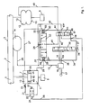
- FIG. 1 shows a schematic representation of a first embodiment of a system according to the invention.
- a loading platform 2 with a loading area 3 also referred to as a use level in the context of the present invention, are shown schematically.
- This loading area 3 is in the entire length and width of a flat surface, which is passable by a forklift.
- the cargo area 3 can be loaded with piece goods.
- an axis 5 of the semitrailer 1 is shown schematically.
- an air spring bellows 12 is arranged between the axis 5 and the platform 2. This is arranged with its end faces 13 of the platform 2 and the axis 5 facing.
- a hydraulic cylinder 7 is provided between the platform 2 and the axis 5, which is filled with a hydraulic fluid and comprises a piston 8.
- the piston 8 divides the hydraulic cylinder 7 into two working spaces 10, 11, an upper working space 10 and a lower working space 11.
- the hydraulic cylinder 7 is coupled with its lower surface to the axis 5.
- the piston 8 is coupled to the platform 2.
- the working spaces 10, 11 of the hydraulic cylinder 7 are connected to each other via a bypass line 21.
- a closing valve 22 is provided which can be transferred by an actuating element 24 against the force of a spring 51 from the open state to the closed state.
- an adjustable throttle valve 23 is provided in the bypass line 21, which comes into the open state of the closing valve 22 to the train. Since the piston 8 in the hydraulic cylinder 7, the working chambers 10, 11 seals against each other by means of a seal 20, pressure relief valves 49 are provided which hold a pressure load below a maximum limit.
- a compressed air reservoir 14 is provided, which is connected via lines 25, 15 with a level control valve 16 in connection.
- the level control valve 16 is equipped in a known manner with a lever 17 operating as a level sensor.
- This control unit 34 comprises three valve devices 32, 39, 45.
- the first valve device 32 is designed as a 3/3-valve and provided with pressure sensors 29, 30.
- the pressure sensors are designed as actuators 33 with springs 31.
- the first pressure sensor 29 is coupled via an input 52 of the control unit 34 and via a pneumatic line 28 to the lower working space 11 of the hydraulic cylinder 7.
- the second pressure sensor 30 is connected via an input 53 of the control unit 34 and via a pneumatic line 27 to the upper working chamber 10 of the hydraulic cylinder 7.
- the first valve device 32 is connected via an input 26 of the control unit 34 and a pneumatic line 42 and a pneumatic line 25 to the compressed air reservoir 14 in connection. Via a further line 41, the first valve device 32 is connected to a third valve device 45 described in detail below.
- the control unit 34 comprises a second valve device 39, which is designed as a lifting / lowering valve and can interact with the level control valve 16.
- the second valve device via an input 36 of the control unit 34 and two pneumatic lines 18, 19 connected to the level control device 16.
- the second valve device 39 is connected via a pneumatic line 40 to the third valve device 45 described in detail below.
- an actuator 37 is connected via an input 38 of the control unit 34, via which the second valve means 39 can be converted into their various switching states. With the second valve device 39 four different switching states can be realized.
- the third valve device 45 is connected via an output 44 and a pneumatic line 43 to the air spring bellows 12. Via a pneumatic line 41, the third valve device 45 is connected to the first valve device 32. The third valve device 45 is further connected via a pneumatic line 40 to the second valve device. Furthermore, the third valve device 45 via an input 50 of the control unit 34 and the pneumatic lines 42 and 25 connected to the compressed air reservoir 14. The third valve device 45 is further connected via an output 48 and a pneumatic line 35 with the actuating element 24 of the closing valve 22 in connection. Further, the third valve means 45 via an input 46 by means of an actuating element 47 in various switching states can be transferred. With the third valve device 45 two different switching states can be realized.
- the third valve device 45 is in its first operating state, in which the pneumatic line 40 is in communication with the pneumatic line 43 and in which the pneumatic line 35 is connected to a vent. Due to the connection of the pneumatic line 35 with the vent, the spring 51 drives the closing valve 22 against the deactivated actuator 24 in the open position of the closing valve 22, so that the working spaces 10, 11 of the hydraulic cylinder 7 can communicate with each other.
- the hydraulic cylinder 7 can thus perform a shock absorber function, which can preferably still be influenced by the controlled throttle 23.
- the second valve device 39 is in driving condition in the state in which the pneumatic line 18 is in communication with the pneumatic line 40. As a result, there is a connection between the level control valve 16 and the air spring bellows 12, so that a level control while driving in a known manner can be done.
- the system can be transferred to a second operating state. This is done by switching the second valve device 39 by means of the actuating element 37 in the switching state in which the level control valve 16 is decoupled from the line 40. There is thus no further level control. If now the semitrailer 1 are to be loaded, the loading area 3 is brought to the level of a loading ramp by further actuation of the actuating device 37. If, for this purpose, the loading area 3 has to be lowered, the second valve device 39 is transferred to the state in which the pneumatic line 40 is connected to the venting of the second valve device 39. This results in a venting of the air spring bellows 12 via the pneumatic line 43, the second valve means 43 and the pneumatic line 40.
- the second valve means 39 is transferred to the state in which the pneumatic line 19 with the pneumatic line 40 is connected.
- the air spring bellows 12 can be ventilated via the pneumatic line 40, the third valve device 45 and the pneumatic line 43.
- the second valve device 39 is transferred to the state in which both the pneumatic line 18 and the pneumatic line 19 are decoupled from the pneumatic line 40. There is therefore no ventilation and no ventilation instead.
- the level control valve 16 is deactivated.
- the third valve means 45 is transferred via the actuator 47 in the switching state in which the pneumatic Line 42 is connected to the pneumatic line 35 and the pneumatic line 44 with the pneumatic Line 41 is connected. Due to the connection of the pneumatic line 35 with the pneumatic line 42, the actuating element 24 of the closing valve 22 is acted upon by compressed air, so that the closing valve 22 is brought against the spring force of the spring 51 in a closed state. The working spaces 10, 11 of the hydraulic cylinder are thus decoupled from each other. Now drives the forklift on the bed 3, so the piston 50 can help that the loading area is supported.
- the pressure in the lower working space 11 of the hydraulic cylinder 7 increases, so that pressure is applied via the pneumatic line 28 to the pressure sensor 29.
- the first valve device can thus be transferred to the state in which via the inlet 26, the pneumatic line 42 and the pneumatic line 25, the compressed air reservoir 14 is connected to the pneumatic line 41. Since the pneumatic line 41 is connected via the third valve device 45 to the pneumatic line 43, the air spring bellows is vented, so that a drop in the loading surface 3 can be compensated.
- the design of the actuators 33 on the first valve device is important.
- the response pressures can be set, in which the first valve device 32 switches. It can be provided, for example, that the two compression springs 31 have different spring characteristics, wherein in the pressure sensor 29, a larger response value than in the pressure sensor 30 can be realized.
- the response value in the pressure sensor 29 may for example be selected so that it is greater than the pressure that occurs in the lower working space 11 when a unloaded forklift stands or travels on the loading surface 3 with a maximum permissible weight.
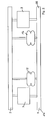
- FIG. 2 shows a schematic representation for explaining the arrangement of inventive systems in the vehicle.
- the hydraulic cylinders 7 are respectively installed at the ends 56 of the vehicle axle 5.
- the air springs 12 and the (not shown) level control valves are arranged.
- FIG. 3 shows a schematic representation of a second embodiment of a system according to the invention.
- the hydraulic cylinder 7 and the air spring bellows 12 are arranged in the same way between the vehicle axle 5 and platform 2 of a semitrailer 1, as in the embodiment according to FIG. 1 ,
- the control unit 34 ' is formed differently from the control unit 34 according to FIG. 1
- components of the system that communicate with the controller 34 ' are configured differently than the corresponding components of FIG. 1.
- the control unit 34 includes an electronic controller 57 having a microcontroller 58.
- the electronic control 57 is connected via an output 48 'and an electrical line 25' to an electrically controllable actuating element 24 'of the closing valve 22.
- This actuator 24 ' may be pneumatically assisted via a pneumatic conduit 68 connected to the compressed air reservoir 14 via the input 26 of the controller 34' and the conduit 25.
- the electronic controller 57 is further connected via an input 36 'and an electrical line 19' with a level sensor 70 which cooperates with a lever 17 in a known manner.
- the electronic control 57 is connected to an actuating element 37'. This is used to transfer the level control in different operating conditions, such as "ride”, “stop”, “lifting” and “sinks".
- the electronic controller 57 is connected via an input 46 'with another actuator 47', set on the operating condition of the system with respect to the operation of the hydraulic cylinder 7 becomes. It is also possible to combine the functions of the actuators 37 'and 47', namely by the operating conditions of the level control and the hydraulic cylinder 7 are meaningfully matched to each other. For example, whenever the hydraulic cylinder 7 is in its closed-loop operating state, the level control should be deactivated. Conversely, the level control should be activated when the hydraulic cylinder 7 acts as a shock absorber, namely when the vehicle is running.
- the electronic controller 57 is connected via an input 67 and an electrical line 66 to a speed sensor 65, so that an automatic switching of the system can take place as a function of the speed. For example, when a speed threshold is exceeded, the level control can be activated, and the closure valve 22 can be opened to provide the shock absorber function.
- FIG. 3 illustrated embodiment of the present invention are on the hydraulic cylinder 7 pressure sensor 29 ', 30' for the lower working space 11 and the upper working space 10 is provided.
- These pressure sensors 29 ', 30' are connected via inputs 52 ', 53' and electrical lines 59, 60 to inputs 61, 62 of the electronic control 57.
- the electronic controller 57 Via an output 63 and an electrical line 68, the electronic controller 57 is connected to an actuating element 33 'of the first valve device 32'.
- the electronic controller 57 is connected to a further actuating element 33 'of the first valve device 32'.
- These electrically controlled actuators 33 ' can be pneumatically assisted by a connection to the compressed air tank 14 when switching the first valve device 32'.
- the air-guiding tasks must be taken over by this first valve device 32 ', both while driving and while the vehicle is stationary. Maintaining the level during loading and unloading of the vehicle is similarly performed by the first valve device 32 ', as in the embodiment of FIG. 1 the case was, however, electrical signals of the control device 57 are used to control the actuators 33 ', which are output in response to the electrical signals supplied by the pressure sensors 29, 30. But even during the drive of the vehicle, the first valve means 32 'is used. In this case, a level control device is formed by the level sensor 70 interacting with the first valve device 32 'through the intermediary of the electronic control device 38 in such a way that the air spring bellows 12 can be ventilated and vented as required.
- the electronic controller 57 or the microcontroller 58 is programmed in such a way that output signals can be given to the actuating elements 33 'as a function of predetermined response pressure values recorded by the pressure sensors 29, 30. These set pressure values may be set to be equal to the pressure existing at the moment when the unloaded forklift loads its full weight onto the bed. These pressure values can be determined empirically, for example. It is also conceivable that a control element is arranged at a further input of the electronic control, with which the response pressure in dependence on the forklift mass can be adjusted. The microcontroller 58 may be further programmed to issue a command to compensate for one third of the measured load increase. This matches with An empirical value, since the forklift may not load more than half of its own weight.
Landscapes
- Engineering & Computer Science (AREA)
- Mechanical Engineering (AREA)
- Vehicle Body Suspensions (AREA)
- Current-Collector Devices For Electrically Propelled Vehicles (AREA)
- Steering-Linkage Mechanisms And Four-Wheel Steering (AREA)
Claims (30)
- Système à maintenir le niveau d'un plan utile (2) d'un véhicule, comprenant- au moins un soufflet de suspension pneumatique (12) et- au moins un moyen de nivelage à aérer et désaérer ledit soufflet de suspension pneumatique (12),
caractérisé en ce- qu'au moins une unité de commande (34, 34') est incorporée, qui active ou respectivement désactive ledit moyen de nivelage,- qu'au moins un cylindre hydraulique (7) est incorporé, qui appuie ledit plan utile (2) et qui est apte à être commandé par ladite unité de commande (34, 34') en au moins un premier état de marche et un deuxième état de marche,- qu'en ledit premier état de marche dudit cylindre hydraulique (7), on peut compenser des variations de pression dans ledit cylindre hydraulique (7), qui sont engendrées par chargement dudit plan utile (2), et- qu'en ledit deuxième état de marche dudit cylindre hydraulique (7), des variations de pression dans ledit cylindre hydraulique (7), qui sont engendrées par chargement dudit plan utile (2), prennent de l'influence sur ladite unité de commande (34, 34') d'une telle manière, que l'aération ou désaération d'au moins un soufflet de suspension pneumatique (12) soit possible. - Système selon la revendication 1, caractérisé en ce que ledit au moins un cylindre hydraulique (7) est disposé à proximité dudit au moins un soufflet de suspension pneumatique (12) entre un essieu (5) et ledit plan utile (2) du véhicule.
- Système selon la revendication 1 ou 2, caractérisé en ce qu'une pluralité de cylindres hydrauliques (7) et des soufflets de suspension pneumatique sont prévus, qui sont disposés en paires.
- Système selon une quelconque des revendications précédentes, caractérisé en ce- que ledit au moins un cylindre hydraulique (7) comprend un premier espace de travail (10) et un deuxième espace de travail (11), lesquels espaces sont séparés l'un de l'autre par un piston (50),- que lesdits espaces de travail (10) sont reliés l'un à l'autre par un conduit de dérivation (21) pourvu d'une soupape de fermeture (22) commandable via ladite unité de commande (34, 34'), à ladite soupape de fermeture (22) étant ouverte en ledit premier état de marche dudit cylindre hydraulique (7) d'une telle façon, qu'une compensation de pression se réalise entre lesdits espaces de travail (10, 11), et à ladite soupape de fermeture (22) étant fermée en ledit deuxième état de marche dudit cylindre hydraulique (7) d'une telle façon, qu'il soit possible d'établir des pressions différentes dans lesdits espaces de travail (10, 11) dudit cylindre hydraulique (7) en chargeant ou respectivement déchargeant ledit piston (50), et donc de prendre de l'influence sur ladite unité de commande (34, 34').
- Système selon une quelconque des revendications précédentes, caractérisé en ce qu'une soupape d'étranglement (23) commandable est incorporée dans ledit conduit de dérivation, en particulier pour la réalisation d'une fonction d'amortisseur dudit cylindre hydraulique (7).
- Système selon une quelconque des revendications précédentes, caractérisé en ce qu'au moins un limiteur de pression (40) est incorporé dans ledit au moins un cylindre hydraulique (7), qui permet une compensation de pression en dessus d'une pression limite prédéterminée même quand ladite soupape de fermeture (22) est fermée.
- Système selon une quelconque des revendications précédentes, caractérisé en ce que ladite unité de commande (34, 34') comprend un premier moyen de soupape (32, 32'), audit premier moyen de soupape (32, 32') étant apte à être commuté par ledit cylindre hydraulique (7) directement ou indirectement en une pluralité d'états de commutation en ledit deuxième état de marche dudit cylindre hydraulique, renfermant- un premier état de commutation à coupler ledit soufflet de suspension pneumatique (12) à un accumulateur de l'air comprimé (14),- un deuxième état de commutation à découpler ledit soufflet de suspension pneumatique (12) dudit accumulateur de l'air comprimé (14), et- un troisième état de commutation à désaérer ledit soufflet de suspension pneumatique (12).
- Système selon une quelconque des revendications précédentes, caractérisé en ce que la commutation dudit premier moyen de soupape (32) en ladite pluralité d'états de commutation se fait moyennant des capteurs de pression intermédiaires (29, 30) disposés audit premier moyen de soupape (32).
- Système selon une quelconque des revendications précédentes, caractérisé en ce que ladite unité de commande (34) comprend un deuxième moyen de soupape ajustable à la main (39), établissant- un premier état de commutation, dans lequel ledit au moins un moyen de nivelage (16) est accouplé audit au moins un soufflet de suspension pneumatique (12),- un deuxième état de commutation, dans lequel ledit au moins un moyen de nivelage (16) est découplé dudit au moins un soufflet de suspension pneumatique (12),- un troisième état de commutation à abaisser ledit plan utile (2), et- un quatrième état de commutation à soulever ledit plan utile (2).
- Système selon une quelconque des revendications précédentes, caractérisé en ce que ladite unité de commande (34) comprend un deuxième moyen de soupape ajustable à la main (39), établissant- un premier état de commutation à établir ledit premier état de marche dudit cylindre hydraulique (7), et- un deuxième état de commutation à établir ledit deuxième état de marche dudit cylindre hydraulique (7).
- Système selon une quelconque des revendications précédentes, caractérisé en ce que la commutation dudit premier moyen de soupape (32') en ladite pluralité d'états de commutation se fait moyennant des capteurs de pression intermédiaires (29', 30'), qui sont disposés audit au moins un cylindre hydraulique (7).
- Système selon une quelconque des revendications précédentes, caractérisé en ce que ladite unité de commande (34') comprend un système de réglage électronique (57).
- Système selon la revendication 12, caractérisé en ce que ledit système de réglage électronique (57) règle, de façon électrique, ledit premier moyen de soupape (32') et ladite soupape de fermeture (22).
- Système selon la revendication 12 ou 13, caractérisé en ce que l'actionnement dudit premier moyen de soupape (32') et de ladite soupape de fermeture (22), qui se fait en réponse à la régulation électrique, est assisté en régime pneumatique.
- Système selon une quelconque des revendications 12 à 14, caractérisé en ce- que ledit premier moyen de soupape (32'), en interaction avec un détecteur de niveau (70), réalise ledit premier état de marche, pendant que ledit cylindre hydraulique (7) se trouve en son premier état de marche, et- en ce que ledit cylindre hydraulique (7) se trouve en son deuxième état de marche au cours dudit deuxième état de marche dudit moyen de nivelage.
- Système selon une quelconque des revendications 12 à 15, caractérisé en ce que ledit système de réglage électronique (57) est capable de commuter en l'état actif dudit moyen de nivelage en fonction d'un signal de vitesse.
- Procédé à maintenir le niveau d'un plan utile d'un véhicule, dans lequel- ledit plan utile (2) est appuyé par au moins un soufflet de suspension pneumatique (12), et- en un premier état actif de marche d'au moins un moyen de nivelage, se fait l'aération ou respectivement la désaération dudit soufflet de suspension pneumatique (12),
caractérisé en ce- que la commutation entre ledit premier état de marche dudit moyen de nivelage et un deuxième état de marche dudit moyen de nivelage est induit par au moins une unité de commande (34, 34'), audit moyen de nivelage étant activé en ledit deuxième état de marche,- que ladite unité de commande (34, 34') induit la commutation entre au moins un premier état de marche et un deuxième état de marche d'au moins un cylindre hydraulique (7) appuyant ledit plan utile (2),- qu'en ledit premier état de marche dudit cylindre hydraulique (7), des variations de pression dans ledit cylindre hydraulique (7), qui sont engendrées par chargement dudit plan utile (2), sont compensées, et- en ce qu'en ledit deuxième état de marche dudit cylindre hydraulique (7), des variations de pression dans ledit cylindre hydraulique (7), qui sont engendrées par chargement dudit plan utile (2), prennent de l'influence sur ladite unité de commande (34, 34') d'une telle manière, que l'aération ou la désaération dudit au moins un soufflet de suspension pneumatique (12) soit possible. - Procédé selon la revendication 17, caractérisé en ce que ledit au moins un cylindre hydraulique (7) comprend un premier espace de travail (10) et un deuxième espace de travail (11), lesquels espaces sont séparés l'un de l'autre par un piston (50), et en ce que lesdits espaces de travail (10, 11) sont reliés l'un à l'autre par un conduit de dérivation (21) pourvu d'une soupape de fermeture (22) commandable via ladite unité de commande (34, 34'), dans lequel- ladite soupape de fermeture (22) est ouverte en ledit premier état de marche dudit cylindre hydraulique (7) d'une telle façon, que la compensation de pression se fasse entre lesdits espaces de travail (10, 11), et- ladite soupape de fermeture (22) est fermée en ledit deuxième état de marche dudit cylindre hydraulique (7) d'une telle façon, que des pressions différentes se puissent établir dans lesdits espaces de travail (10, 11) dudit cylindre hydraulique (7) par chargement ou respectivement déchargement dudit piston (50), et donc ladite unité de commande (34, 34') soit influencée.
- Procédé selon la revendication 17 ou 18, caractérisé en ce qu'un courant de fluide dans ledit conduit de dérivation (21) est étranglé en régime de réglage asservi, en particulier à réaliser une fonction d'amortisseur dudit cylindre hydraulique (7).
- Procédé selon une quelconque des revendications 17 à 19, caractérisé en ce qu'au moins un limiteur de pression (49) est incorporé dans ledit au moins un cylindre hydraulique (7), qui permet la compensation de pression en dessus d'une pression limite prédéterminée même quand ladite soupape de fermeture (22) est fermée
- Procédé selon une quelconque des revendications 17 à 20, caractérisé en ce que ladite unité de commande (34, 34') comprend un premier moyen de soupape (32, 32'), audit premier moyen de soupape (32, 32') étant apte à être commue par ledit cylindre hydraulique (7) en une pluralité d'états de commutation en ledit deuxième état de marche dudit cylindre hydraulique, qui renferment- un premier état de commutation à coupler ledit soufflet de suspension pneumatique (12) à un accumulateur de l'air comprimé (14),- un deuxième état de commutation à découpler ledit soufflet de suspension pneumatique (12) dudit accumulateur de l'air comprimé (14), et- un troisième état de commutation à désaérer ledit soufflet de suspension pneumatique (12).
- Procédé selon une quelconque des revendications 17 à 21, caractérisé en ce que la commutation dudit premier moyen de soupape (32) en ladite pluralité d'états de commutation se fait moyennant des capteurs de pression intermédiaires (29, 30) disposés audit premier moyen de soupape (32)
- Procédé selon une quelconque des revendications 17 à 22, caractérisé en ce que ladite unité de commande (34) comprend un deuxième moyen de soupape ajustable à la main (39), établissant- un premier état de commutation, dans lequel ledit au moins un moyen de nivelage (16) est couplé audit au moins un soufflet de suspension pneumatique (12),- un deuxième état de commutation, dans lequel ledit au moins un moyen de nivelage (16) est découplé dudit au moins un soufflet de suspension pneumatique (12),- un troisième état de commutation à abaisser ledit plan utile (2), et- un quatrième état de commutation à soulever ledit plan utile (2).
- Procédé selon une quelconque des revendications 17 à 23, caractérisé en ce que ladite unité de commande (34) comprend un moyen de soupape ajustable à la main (45) et ajustant- un premier état de commutation à établir ledit premier état de marche dudit cylindre hydraulique (7), et- un deuxième état de commutation à établir ledit deuxième état de marche dudit cylindre hydraulique (7).
- Procédé selon une quelconque des revendications 17 à 24, caractérisé en ce que la commutation dudit premier moyen de soupape (32') en ladite pluralité d'états de commutation se fait moyennant des capteurs de pression intermédiaires (29', 39') disposés audit au moins un cylindre hydraulique (7).
- Procédé selon une quelconque des revendications 17 à 25, caractérisé en ce que ladite unité de commande (34') comprend un système de réglage électronique (57).
- Procédé selon la revendication 26, caractérisé en ce que ledit système de réglage électronique (57) règle, de façon électrique, ledit premier moyen de soupape (32') et ladite soupape de fermeture (22).
- Procédé selon la revendication 26 ou 27, caractérisé en ce que l'actionnement dudit premier moyen de soupape (32') et de ladite soupape de fermeture (22) est assisté, en régime pneumatique, en réponse audit réglage électrique.
- Procédé selon une quelconque des revendications 26 à 28, caractérisé en ce que ledit système de réglage électronique (57) règle ledit premier moyen de soupape (32') d'une telle manière,- que ledit premier moyen de soupape (32'), en interaction avec un détecteur de niveau (70), réalise ledit premier état de marche, pendant que ledit cylindre hydraulique (7) se trouve en son premier état de marche, et- que ledit cylindre hydraulique (7) se trouve en son deuxième état de marche au cours dudit deuxième état de marche dudit moyen de nivelage.
- Procédé selon une quelconque des revendications 26 à 29, caractérisé en ce que ledit système de réglage électronique (57) est capable de commuter en l'état actif dudit moyen de nivelage en fonction d'un signal de vitesse.
Applications Claiming Priority (3)
| Application Number | Priority Date | Filing Date | Title |
|---|---|---|---|
| DE10235473A DE10235473B4 (de) | 2002-08-02 | 2002-08-02 | Vorrichtung und Verfahren zum Aufrechterhalten des Niveaus einer Nutzebene eines Fahrzeugs |
| DE10235473 | 2002-08-02 | ||
| PCT/EP2003/008525 WO2004014675A1 (fr) | 2002-08-02 | 2003-08-01 | Systeme et procede pour maintenir le niveau d'un plan utile d'un vehicule |
Publications (2)
| Publication Number | Publication Date |
|---|---|
| EP1528989A1 EP1528989A1 (fr) | 2005-05-11 |
| EP1528989B1 true EP1528989B1 (fr) | 2008-05-07 |
Family
ID=30128677
Family Applications (1)
| Application Number | Title | Priority Date | Filing Date |
|---|---|---|---|
| EP03784138A Expired - Lifetime EP1528989B1 (fr) | 2002-08-02 | 2003-08-01 | Systeme et procede pour maintenir le niveau d'un plan utile d'un vehicule |
Country Status (5)
| Country | Link |
|---|---|
| EP (1) | EP1528989B1 (fr) |
| AT (1) | ATE394254T1 (fr) |
| AU (1) | AU2003258558A1 (fr) |
| DE (2) | DE10235473B4 (fr) |
| WO (1) | WO2004014675A1 (fr) |
Family Cites Families (10)
| Publication number | Priority date | Publication date | Assignee | Title |
|---|---|---|---|---|
| CA1102829A (fr) * | 1978-07-27 | 1981-06-09 | Herbert E. Gladish | Traduction non-disponible |
| DD146494A1 (de) | 1979-10-10 | 1981-02-11 | Wieland Feist | Verfahren zum ausmessen der lage eines index |
| US4553773A (en) * | 1983-08-05 | 1985-11-19 | Lear Siegler, Inc. | Load equalizer valve and suspension system |
| JPH048613A (ja) * | 1990-04-24 | 1992-01-13 | Hino Motors Ltd | 車両用サスペンション装置 |
| NL9101255A (nl) * | 1991-07-17 | 1993-02-16 | Weweler Nv | Inrichting voor het fixeren van de hoogtestand van een gestel van een voertuig. |
| DE19539878A1 (de) | 1995-10-26 | 1997-04-30 | Klein Schanzlin & Becker Ag | Wärmeaustauscher für die Magnetkupplung einer Kreiselpumpe |
| DE19539887B4 (de) * | 1995-10-26 | 2008-07-10 | Knorr-Bremse Systeme für Nutzfahrzeuge GmbH | Vorrichtung zur Regelung eines Fahrzeugaufbauniveaus |
| FR2755402B1 (fr) * | 1996-11-06 | 1999-01-22 | Europ Semi Remorques | Dispositif de maintien a niveau d'un chassis |
| JP3924100B2 (ja) * | 1999-10-22 | 2007-06-06 | 日野自動車株式会社 | 車高調整方法 |
| DE10231245A1 (de) * | 2002-07-11 | 2004-01-22 | Wabco Gmbh & Co. Ohg | Verfahren zum Konstanthalten eines Fahrzeugniveaus |
-
2002
- 2002-08-02 DE DE10235473A patent/DE10235473B4/de not_active Expired - Fee Related
-
2003
- 2003-08-01 AU AU2003258558A patent/AU2003258558A1/en not_active Abandoned
- 2003-08-01 WO PCT/EP2003/008525 patent/WO2004014675A1/fr not_active Ceased
- 2003-08-01 DE DE50309795T patent/DE50309795D1/de not_active Expired - Lifetime
- 2003-08-01 EP EP03784138A patent/EP1528989B1/fr not_active Expired - Lifetime
- 2003-08-01 AT AT03784138T patent/ATE394254T1/de not_active IP Right Cessation
Also Published As
| Publication number | Publication date |
|---|---|
| AU2003258558A1 (en) | 2004-02-25 |
| DE10235473A1 (de) | 2004-02-12 |
| DE50309795D1 (de) | 2008-06-19 |
| WO2004014675A1 (fr) | 2004-02-19 |
| ATE394254T1 (de) | 2008-05-15 |
| EP1528989A1 (fr) | 2005-05-11 |
| DE10235473B4 (de) | 2007-12-27 |
Similar Documents
| Publication | Publication Date | Title |
|---|---|---|
| EP1502778B2 (fr) | Système de traitement de l'air comprimé pour véhicules | |
| EP2757006B1 (fr) | Système de soupape pour une installation d'air comprimé d'une remorque de véhicule utilitaire | |
| DE19622677C2 (de) | Fahrzeug mit niveaugeregeltem Federungssystem | |
| DE19914647C2 (de) | Federungssystem für Landfahrzeuge, insbesondere Kraftfahrzeuge | |
| EP2125398B1 (fr) | Système de suspension pneumatique pourvu de soupapes de commande actionnées exclusivement par un fluide sous pression | |
| EP0453752A1 (fr) | Autobus, en particulier à plate-forme surbaissée | |
| EP2794310B1 (fr) | Suspension pneumatique pour vehicule automobile | |
| DE20208577U1 (de) | Elektrohydraulische Hubsteuervorrichtung für Flurförerfahrzeuge | |
| EP2168788A1 (fr) | Dispositif et procédé d'exécution d'un réglage de la position d'une roue pour véhicules utilitaires | |
| EP3145737A1 (fr) | Procédé de réglage du niveau d'un véhicule automobile à suspension pneumatique | |
| DE102008028676A1 (de) | Dämpferbetätigte aktive Rollsteuerung | |
| DE102013105759B4 (de) | Fahrzeug-Gasfederungssystem und Verfahren zur Niveauregulierung eines Kraftfahrzeugs | |
| DE2848286A1 (de) | Hydropneumatische aufhaengung fuer ein fahrzeug | |
| DE60225805T2 (de) | Steuersystem für die aufhängung eines fahrzeugs | |
| EP2381146A2 (fr) | Soupape | |
| DE102010011432B4 (de) | Ventileinrichtung für eine Luftfederungsanlage | |
| WO2010043594A1 (fr) | Arrangement de soupapes et installation à ressort pour un véhicule | |
| DE4327764C2 (de) | Luftfederungsanlage | |
| EP4197829B1 (fr) | Remorque avec dispositif de soupape électromagnétique et procédé de commande du dispositif de soupape électromagnétique de la remorque | |
| EP0910513A1 (fr) | Groupe essieu a suspension pneumatique et a regulation de garde au sol, par exemple pour voitures particulieres de type monospace | |
| DE102005030467B4 (de) | Luftfederungseinrichtung für Fahrzeuge mit Drossel | |
| EP1528989B1 (fr) | Systeme et procede pour maintenir le niveau d'un plan utile d'un vehicule | |
| DE102007033527A1 (de) | Fahrzeug mit drei Achsen und einer Vorrichtung zur Steuerung oder Regelung der Achs- bzw. Radlasten | |
| EP2662228B1 (fr) | Ressort pneumatique d'un véhicule utilitaire avec commutation de charge d'essieu entre l'essieu arrière et l'essieu avant ou l'essieu entraîné | |
| DE102013100295B4 (de) | Luftfederanlage für ein Fahrzeug |
Legal Events
| Date | Code | Title | Description |
|---|---|---|---|
| PUAI | Public reference made under article 153(3) epc to a published international application that has entered the european phase |
Free format text: ORIGINAL CODE: 0009012 |
|
| 17P | Request for examination filed |
Effective date: 20050302 |
|
| AK | Designated contracting states |
Kind code of ref document: A1 Designated state(s): AT BE BG CH CY CZ DE DK EE ES FI FR GB GR HU IE IT LI LU MC NL PT RO SE SI SK TR |
|
| AX | Request for extension of the european patent |
Extension state: AL LT LV MK |
|
| DAX | Request for extension of the european patent (deleted) | ||
| GRAP | Despatch of communication of intention to grant a patent |
Free format text: ORIGINAL CODE: EPIDOSNIGR1 |
|
| GRAS | Grant fee paid |
Free format text: ORIGINAL CODE: EPIDOSNIGR3 |
|
| GRAA | (expected) grant |
Free format text: ORIGINAL CODE: 0009210 |
|
| AK | Designated contracting states |
Kind code of ref document: B1 Designated state(s): AT BE BG CH CY CZ DE DK EE ES FI FR GB GR HU IE IT LI LU MC NL PT RO SE SI SK TR |
|
| REG | Reference to a national code |
Ref country code: GB Ref legal event code: FG4D Free format text: NOT ENGLISH |
|
| REG | Reference to a national code |
Ref country code: CH Ref legal event code: EP |
|
| REG | Reference to a national code |
Ref country code: IE Ref legal event code: FG4D Free format text: LANGUAGE OF EP DOCUMENT: GERMAN |
|
| REF | Corresponds to: |
Ref document number: 50309795 Country of ref document: DE Date of ref document: 20080619 Kind code of ref document: P |
|
| REG | Reference to a national code |
Ref country code: SE Ref legal event code: TRGR |
|
| PG25 | Lapsed in a contracting state [announced via postgrant information from national office to epo] |
Ref country code: SI Free format text: LAPSE BECAUSE OF FAILURE TO SUBMIT A TRANSLATION OF THE DESCRIPTION OR TO PAY THE FEE WITHIN THE PRESCRIBED TIME-LIMIT Effective date: 20080507 |
|
| PG25 | Lapsed in a contracting state [announced via postgrant information from national office to epo] |
Ref country code: ES Free format text: LAPSE BECAUSE OF FAILURE TO SUBMIT A TRANSLATION OF THE DESCRIPTION OR TO PAY THE FEE WITHIN THE PRESCRIBED TIME-LIMIT Effective date: 20080818 Ref country code: FI Free format text: LAPSE BECAUSE OF FAILURE TO SUBMIT A TRANSLATION OF THE DESCRIPTION OR TO PAY THE FEE WITHIN THE PRESCRIBED TIME-LIMIT Effective date: 20080507 |
|
| REG | Reference to a national code |
Ref country code: IE Ref legal event code: FD4D |
|
| PG25 | Lapsed in a contracting state [announced via postgrant information from national office to epo] |
Ref country code: IE Free format text: LAPSE BECAUSE OF FAILURE TO SUBMIT A TRANSLATION OF THE DESCRIPTION OR TO PAY THE FEE WITHIN THE PRESCRIBED TIME-LIMIT Effective date: 20080507 Ref country code: PT Free format text: LAPSE BECAUSE OF FAILURE TO SUBMIT A TRANSLATION OF THE DESCRIPTION OR TO PAY THE FEE WITHIN THE PRESCRIBED TIME-LIMIT Effective date: 20081007 Ref country code: DK Free format text: LAPSE BECAUSE OF FAILURE TO SUBMIT A TRANSLATION OF THE DESCRIPTION OR TO PAY THE FEE WITHIN THE PRESCRIBED TIME-LIMIT Effective date: 20080507 Ref country code: CZ Free format text: LAPSE BECAUSE OF FAILURE TO SUBMIT A TRANSLATION OF THE DESCRIPTION OR TO PAY THE FEE WITHIN THE PRESCRIBED TIME-LIMIT Effective date: 20080507 |
|
| PG25 | Lapsed in a contracting state [announced via postgrant information from national office to epo] |
Ref country code: SK Free format text: LAPSE BECAUSE OF FAILURE TO SUBMIT A TRANSLATION OF THE DESCRIPTION OR TO PAY THE FEE WITHIN THE PRESCRIBED TIME-LIMIT Effective date: 20080507 Ref country code: RO Free format text: LAPSE BECAUSE OF FAILURE TO SUBMIT A TRANSLATION OF THE DESCRIPTION OR TO PAY THE FEE WITHIN THE PRESCRIBED TIME-LIMIT Effective date: 20080507 |
|
| PLBE | No opposition filed within time limit |
Free format text: ORIGINAL CODE: 0009261 |
|
| STAA | Information on the status of an ep patent application or granted ep patent |
Free format text: STATUS: NO OPPOSITION FILED WITHIN TIME LIMIT |
|
| PG25 | Lapsed in a contracting state [announced via postgrant information from national office to epo] |
Ref country code: MC Free format text: LAPSE BECAUSE OF NON-PAYMENT OF DUE FEES Effective date: 20080831 |
|
| REG | Reference to a national code |
Ref country code: CH Ref legal event code: PL |
|
| 26N | No opposition filed |
Effective date: 20090210 |
|
| GBPC | Gb: european patent ceased through non-payment of renewal fee |
Effective date: 20080807 |
|
| PG25 | Lapsed in a contracting state [announced via postgrant information from national office to epo] |
Ref country code: BG Free format text: LAPSE BECAUSE OF FAILURE TO SUBMIT A TRANSLATION OF THE DESCRIPTION OR TO PAY THE FEE WITHIN THE PRESCRIBED TIME-LIMIT Effective date: 20080807 Ref country code: EE Free format text: LAPSE BECAUSE OF FAILURE TO SUBMIT A TRANSLATION OF THE DESCRIPTION OR TO PAY THE FEE WITHIN THE PRESCRIBED TIME-LIMIT Effective date: 20080507 |
|
| PG25 | Lapsed in a contracting state [announced via postgrant information from national office to epo] |
Ref country code: CH Free format text: LAPSE BECAUSE OF NON-PAYMENT OF DUE FEES Effective date: 20080831 Ref country code: LI Free format text: LAPSE BECAUSE OF NON-PAYMENT OF DUE FEES Effective date: 20080831 |
|
| PG25 | Lapsed in a contracting state [announced via postgrant information from national office to epo] |
Ref country code: BE Free format text: LAPSE BECAUSE OF NON-PAYMENT OF DUE FEES Effective date: 20080831 |
|
| PG25 | Lapsed in a contracting state [announced via postgrant information from national office to epo] |
Ref country code: IT Free format text: LAPSE BECAUSE OF FAILURE TO SUBMIT A TRANSLATION OF THE DESCRIPTION OR TO PAY THE FEE WITHIN THE PRESCRIBED TIME-LIMIT Effective date: 20080507 |
|
| PG25 | Lapsed in a contracting state [announced via postgrant information from national office to epo] |
Ref country code: AT Free format text: LAPSE BECAUSE OF NON-PAYMENT OF DUE FEES Effective date: 20080801 |
|
| PG25 | Lapsed in a contracting state [announced via postgrant information from national office to epo] |
Ref country code: GB Free format text: LAPSE BECAUSE OF NON-PAYMENT OF DUE FEES Effective date: 20080807 |
|
| PG25 | Lapsed in a contracting state [announced via postgrant information from national office to epo] |
Ref country code: LU Free format text: LAPSE BECAUSE OF NON-PAYMENT OF DUE FEES Effective date: 20080801 Ref country code: HU Free format text: LAPSE BECAUSE OF FAILURE TO SUBMIT A TRANSLATION OF THE DESCRIPTION OR TO PAY THE FEE WITHIN THE PRESCRIBED TIME-LIMIT Effective date: 20081108 Ref country code: CY Free format text: LAPSE BECAUSE OF FAILURE TO SUBMIT A TRANSLATION OF THE DESCRIPTION OR TO PAY THE FEE WITHIN THE PRESCRIBED TIME-LIMIT Effective date: 20080507 |
|
| PG25 | Lapsed in a contracting state [announced via postgrant information from national office to epo] |
Ref country code: TR Free format text: LAPSE BECAUSE OF FAILURE TO SUBMIT A TRANSLATION OF THE DESCRIPTION OR TO PAY THE FEE WITHIN THE PRESCRIBED TIME-LIMIT Effective date: 20080507 |
|
| PG25 | Lapsed in a contracting state [announced via postgrant information from national office to epo] |
Ref country code: GR Free format text: LAPSE BECAUSE OF FAILURE TO SUBMIT A TRANSLATION OF THE DESCRIPTION OR TO PAY THE FEE WITHIN THE PRESCRIBED TIME-LIMIT Effective date: 20080808 |
|
| PGFP | Annual fee paid to national office [announced via postgrant information from national office to epo] |
Ref country code: NL Payment date: 20100823 Year of fee payment: 8 |
|
| REG | Reference to a national code |
Ref country code: FR Ref legal event code: ST Effective date: 20110708 |
|
| PG25 | Lapsed in a contracting state [announced via postgrant information from national office to epo] |
Ref country code: FR Free format text: LAPSE BECAUSE OF NON-PAYMENT OF DUE FEES Effective date: 20080901 |
|
| REG | Reference to a national code |
Ref country code: NL Ref legal event code: V1 Effective date: 20120301 |
|
| PG25 | Lapsed in a contracting state [announced via postgrant information from national office to epo] |
Ref country code: NL Free format text: LAPSE BECAUSE OF NON-PAYMENT OF DUE FEES Effective date: 20120301 |
|
| PGFP | Annual fee paid to national office [announced via postgrant information from national office to epo] |
Ref country code: DE Payment date: 20140821 Year of fee payment: 12 |
|
| REG | Reference to a national code |
Ref country code: DE Ref legal event code: R119 Ref document number: 50309795 Country of ref document: DE |
|
| PG25 | Lapsed in a contracting state [announced via postgrant information from national office to epo] |
Ref country code: DE Free format text: LAPSE BECAUSE OF NON-PAYMENT OF DUE FEES Effective date: 20160301 |
|
| PGFP | Annual fee paid to national office [announced via postgrant information from national office to epo] |
Ref country code: SE Payment date: 20170830 Year of fee payment: 15 |
|
| REG | Reference to a national code |
Ref country code: SE Ref legal event code: EUG |
|
| PG25 | Lapsed in a contracting state [announced via postgrant information from national office to epo] |
Ref country code: SE Free format text: LAPSE BECAUSE OF NON-PAYMENT OF DUE FEES Effective date: 20180802 |