EP1528641A1 - Dispositif de liaison électrique entre deux éléments en mouvement relatif - Google Patents
Dispositif de liaison électrique entre deux éléments en mouvement relatif Download PDFInfo
- Publication number
- EP1528641A1 EP1528641A1 EP03360123A EP03360123A EP1528641A1 EP 1528641 A1 EP1528641 A1 EP 1528641A1 EP 03360123 A EP03360123 A EP 03360123A EP 03360123 A EP03360123 A EP 03360123A EP 1528641 A1 EP1528641 A1 EP 1528641A1
- Authority
- EP
- European Patent Office
- Prior art keywords
- electrical
- connecting device
- branches
- electrical connection
- connector
- Prior art date
- Legal status (The legal status is an assumption and is not a legal conclusion. Google has not performed a legal analysis and makes no representation as to the accuracy of the status listed.)
- Granted
Links
Images

Classifications
-
- H—ELECTRICITY
- H01—ELECTRIC ELEMENTS
- H01R—ELECTRICALLY-CONDUCTIVE CONNECTIONS; STRUCTURAL ASSOCIATIONS OF A PLURALITY OF MUTUALLY-INSULATED ELECTRICAL CONNECTING ELEMENTS; COUPLING DEVICES; CURRENT COLLECTORS
- H01R35/00—Flexible or turnable line connectors, i.e. the rotation angle being limited
- H01R35/04—Turnable line connectors with limited rotation angle with frictional contact members
Definitions
- the present invention relates to the general technical field of the electrical connection and more particularly the connection of parts in relative motion.
- the present invention relates to any application comprising a movable portion, in motion relative to a fixed part, an electrical connection to be established between the parts.
- a movable portion in motion relative to a fixed part, an electrical connection to be established between the parts.
- electrical connection to be established between the parts.
- These latter consist for example of a connector and a moving contact surface.
- the present invention relates more particularly to the field automobile, in which it is often necessary to resort to such connectivity, especially in the environment of the columns of direction. It is therefore often necessary to make a connection between a first fixed element and a second movable element, linked to a housing in motion, for example rotating with the steering wheel direction.
- the interface is connected to the flexible blades by any means and in particular by welding points and must be fixed or must be optimally arranged in relation to moving parts relative and the wires used. This also poses congestion problems often difficult to solve and reliability issues.
- the object of the present invention is to provide a connecting device between moving parts that do not have the same disadvantages of the state of the art and allowing by its use of reduce the number of parts to establish the electrical connection.
- Another object of the present invention is to provide a connection device whose technical characteristics make it possible to respond to different constraints and requirements related to making a sliding contact on the one hand and the connection to a standard connector on the other.
- each electrical branch has two ends of different cross section, the elastic member being realized with the end having the smallest cross section.
- each electrical branch is made of one piece.
- each electrical branch is made of two pieces joined together by welding or riveting points.
- the parts connecting zones components of the electrical branches are covered at least in part by the support, which is made of plastic.
- the support is an overmolded part.
- the first electrical interface presents a series of connection terminals made for the ends, protruding out of the support and intended to be engaged in the connector.
- the elastic members are blades Flexible.
- connection terminals made for the ends and the flexible blades made for the other ends extend in directions having an inclined angular inclination between 30 ° and 180 °, and preferably close to 90 °.
- the present invention also relates to a control under a steering wheel vehicle comprising an electrical connection device as presented above.
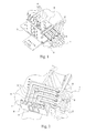
- the electrical connection device according to the invention is shown in FIGS. Figures 1 to 3 is intended to be mounted for example on or in the vicinity of a steering column of a vehicle.
- the electrical connection device makes it possible to electrically connecting a contact surface 1 having conductive tracks 2 to a standard electrical connector not shown.
- the contact surface 1 is for example in motion relative to the electrical connection device.
- the movement is in general but not exclusively a rotation.
- the electrical connection device comprises electrical branches 3 electrically insulated from each other. We can refer for example to Figure 2.
- certain electric branches 3 are electrically connected to each other.
- a first electrical connection interface is made with a first end 4 of the electric branches 3, adapted to the mounting of the connector. These first ends 4 are for example intended to engage in the standard electrical connector.
- a second electrical connection interface is made with the seconds ends 5 of the electric branches 3. These second ends 5 have elastic members making a sliding contact with the contact area 1.
- the electrical connection device also comprises a support 6 in plastic material providing mechanical support for electrical branches 3 between them. This is how the electrical connection device conforms to the invention has different technical characteristics to each of these electrical connection interfaces.
- the standard electrical connector not shown is mounted directly on the first ends 4, and without use of an intermediate piece.
- each electrical branch 3 presents a different cross section at both ends 4 and 5.
- the organs elastics are made with the ends 5 having the smallest section cross. The latter is chosen to guarantee their flexibility and a contact optimal with the contact surface 1, which is made to move for make sliding contacts.
- the end 4 of the electric branches advantageously has a larger cross-section to give them rigidity more important mechanics, which allows them to be engaged indirectly in a standard electrical connector.
- each electrical branch 3 is made in one piece.
- the latter is for example obtained by molding or by cutting and stamping.
- the number of component parts of the electrical connection device is therefore very limited and its realization is particularly simple.
- each electrical branch 3 is made in two pieces interconnected by welding or riveting points. It is so possible to connect together parts with a cross-section more important realizing the first ends 4 to be engaged in the standard electrical connector and cross sectional parts less important properties of elasticity and flexibility to ensure sliding contacts.
- the binding areas of the parties components of the electrical branches 3 are advantageously covered by the support 6 made of plastic.
- the support 6 made of plastic material is example a molded part partially covering the electric branches 3 except the ends 4 and 5 of said branches 3.
- FIG. 2 is a simplified representation partially cut away support 6 made of plastic.
- the first electrical interface present advantageously a series of connection terminals made by the first ends 4 projecting out of the support 6 and intended to be engaged in the electrical connector.
- the second ends 5 are preferably flexible blades constituting the elastic members.
- connection terminals made by the ends 4 and the flexible blades made by the second ends 5 of the electrical branches 3 extend in directions having a angular inclination between 30 and 180 °, and preferably close to 90 °.
- the second ends 5 components of the flexible blades therefore extend substantially parallel or slightly inclined relative to the plane of extension of the contact surface 1 and the connection terminals made by the first ends 4, extend substantially orthogonally with respect to the contact surface 1, facilitating the engagement of the electrical connector.
- the angular orientation between the terminals and the flexible blades can be adjusted.
- the support 6 of plastic is split in a first part 7 and a second part 8.
- the first and second parts 7 and 8 are, for example, overmolded respectively on the branches 3 electrical components of the first and second electrical interface link.
- the electrical connection device according to the invention is particularly well suited for its use in steering wheel controls in the environment of the steering columns of vehicles.
- the support 6 and / or the parts 7, 8 can also constitute one or several electronic circuits. Electronic components can also be positioned between the electrical branches to create specific electrical signals.
- the device according to the invention has the advantage of reducing the number of intermediate parts needed to establish links electric.
- Another advantage of the device according to the invention is related to the large number of mechanical configurations and miniaturization that we can consider.
- the device according to the invention also has a robustness increased electrical connection, even in case of miniaturization.
Landscapes
- Steering Controls (AREA)
Abstract
Description
- un ensemble de branches électriques,
- une première interface de liaison électrique réalisée avec une extrémité des branches électriques et adaptée au montage du connecteur,
- une seconde interface de liaison électrique, réalisée avec l'autre extrémité des branches électriques, lesquelles comportent des organes élastiques établissant un contact glissant avec la surface de contact,
- au moins un support isolant électrique réalisant le maintien mécanique des branches électriques entre-elles.
- la figure 1 est une vue en perspective d'un exemple de réalisation d'un dispositif de liaison électrique conforme à l'invention ;
- la figure 2 représente une vue partiellement découpée à des fins de clarté du dispositif de liaison de la figure 1 ;
- la figure 3 représente un autre exemple de réalisation d'un dispositif de liaison électrique conforme à l'invention.
Claims (10)
- Dispositif de liaison électrique entre un connecteur et une surface de contact (1 ) en mouvement relatif, comportant :un ensemble de branches électriques (3),une première interface de liaison électrique réalisée avec une extrémité (4) des branches électriques (3) et adaptée au montage du connecteur,une seconde interface de liaison électrique, réalisée avec l'autre extrémité (5) des branches électriques (3), lesquelles comportent des organes élastiques établissant un contact glissant avec la surface de contact (1), etet au moins un support (6) isolant électrique, réalisant le maintien mécanique des branches électriques (3) entre-elles.
- Dispositif de liaison selon la revendication 1, caractérisé en ce que chaque branche électrique (3) présente deux extrémités (4, 5) de section transversale différente, l'organe élastique étant réalisé avec l'extrémité présentant la plus faible section transversale.
- Dispositif de liaison selon la revendication 1 ou 2, caractérisé en ce que chaque branche électrique (3) est réalisée en une seule pièce.
- Dispositif de liaison selon la revendication 1 ou 2, caractérisé en ce que chaque branche électrique (3) est réalisée en deux pièces reliées entre elles par des points de soudure ou de rivetage.
- Dispositif de liaison selon la revendication 4, caractérisé en ce que les zones de liaison des pièces constitutives des branches électriques (3) sont recouvertes au moins en partie par le support (6), lequel est réalisé en matière plastique.
- Dispositif de liaison selon l'une quelconque des revendications 1 à 5, caractérisé en ce que le support (6) est une pièce surmoulée.
- Dispositif de liaison selon l'une quelconque des revendications 1 à 6, caractérisé en ce que la première interface électrique présente une série de bornes de connexion réalisées par les extrémités (4), faisant saillie hors du support et destinées à être engagées dans le connecteur électrique.
- Dispositif de liaison selon l'une quelconque des revendications 1 à 7, caractérisé en ce que les organes élastiques sont des lames flexibles.
- Dispositif de liaison selon la revendications 7 et 8, caractérisé en ce que les bornes de connexion réalisées par les extrémités (4) et les lames flexibles réalisées par les autres extrémités (5), s'étendent selon des directions présentant une inclinaison angulaire comprise entre 30° et 180°, et de préférence voisine de 90°.
- Commande sous volant d'un véhicule comportant un dispositif de liaison électrique conforme à l'une quelconque des revendications 1 à 9.
Priority Applications (2)
| Application Number | Priority Date | Filing Date | Title |
|---|---|---|---|
| EP20030360123 EP1528641B1 (fr) | 2003-10-28 | 2003-10-28 | Dispositif de liaison électrique entre deux éléments en mouvement relatif |
| DE2003608031 DE60308031T2 (de) | 2003-10-28 | 2003-10-28 | Verbindung von Stücken in Relativbewegung |
Applications Claiming Priority (1)
| Application Number | Priority Date | Filing Date | Title |
|---|---|---|---|
| EP20030360123 EP1528641B1 (fr) | 2003-10-28 | 2003-10-28 | Dispositif de liaison électrique entre deux éléments en mouvement relatif |
Publications (2)
| Publication Number | Publication Date |
|---|---|
| EP1528641A1 true EP1528641A1 (fr) | 2005-05-04 |
| EP1528641B1 EP1528641B1 (fr) | 2006-08-30 |
Family
ID=34400607
Family Applications (1)
| Application Number | Title | Priority Date | Filing Date |
|---|---|---|---|
| EP20030360123 Expired - Fee Related EP1528641B1 (fr) | 2003-10-28 | 2003-10-28 | Dispositif de liaison électrique entre deux éléments en mouvement relatif |
Country Status (2)
| Country | Link |
|---|---|
| EP (1) | EP1528641B1 (fr) |
| DE (1) | DE60308031T2 (fr) |
Citations (3)
| Publication number | Priority date | Publication date | Assignee | Title |
|---|---|---|---|---|
| US5230713A (en) * | 1990-11-17 | 1993-07-27 | Kabelmetal Electro Gesellschaft Mit Beschrankter Haftung | Device for the transmission of current between two end points |
| US6007344A (en) * | 1995-02-17 | 1999-12-28 | Lear Corporation | Multiple brush steering wheel commutator |
| US6273735B1 (en) * | 2000-10-25 | 2001-08-14 | 3Com Corporation | Rotating turret side-entry retractable jack |
-
2003
- 2003-10-28 DE DE2003608031 patent/DE60308031T2/de not_active Expired - Lifetime
- 2003-10-28 EP EP20030360123 patent/EP1528641B1/fr not_active Expired - Fee Related
Patent Citations (3)
| Publication number | Priority date | Publication date | Assignee | Title |
|---|---|---|---|---|
| US5230713A (en) * | 1990-11-17 | 1993-07-27 | Kabelmetal Electro Gesellschaft Mit Beschrankter Haftung | Device for the transmission of current between two end points |
| US6007344A (en) * | 1995-02-17 | 1999-12-28 | Lear Corporation | Multiple brush steering wheel commutator |
| US6273735B1 (en) * | 2000-10-25 | 2001-08-14 | 3Com Corporation | Rotating turret side-entry retractable jack |
Also Published As
| Publication number | Publication date |
|---|---|
| DE60308031D1 (de) | 2006-10-12 |
| DE60308031T2 (de) | 2007-04-12 |
| EP1528641B1 (fr) | 2006-08-30 |
Similar Documents
| Publication | Publication Date | Title |
|---|---|---|
| FR2684492A1 (fr) | Dispositif d'interconnexion electrique. | |
| FR3026897A1 (fr) | Connecteur electrique | |
| EP3790126B1 (fr) | Ensemble pour connecteurs adapté à un montage en aveugle | |
| FR2685560A1 (fr) | Element de connecteur electrique fixable de facon flottante sur un organe de support. | |
| EP2940800B1 (fr) | Organe de connexion electrique entre deux cartes electroniques et procédé de connexion associé | |
| EP1528641B1 (fr) | Dispositif de liaison électrique entre deux éléments en mouvement relatif | |
| EP2745661B1 (fr) | Dispositif de connexion electrique, ensemble comprenant un tel dispositif et une carte electronique et procede de connexion electrique d'une carte electronique | |
| EP2783423B1 (fr) | Procédé pour la mise en contact d'une carte imprimée électronique avec une pluralité d'éléments de contacts dans un boitier recevant ou entourant la carte imprimée électronique et boitier | |
| FR2946468A1 (fr) | Dispositif de liaison entre un connecteur electrique et un cable electrique coaxial blinde et connecteur electrique correspondant | |
| FR2683397A1 (fr) | Douille electrique pour interconnecter des circuits sur une puce et des circuits sur un substrat. | |
| FR3043523A1 (fr) | Dispositif de pilotage de l'alimentation electrique d'un composant electronique pour vehicule automobile | |
| FR2843655A1 (fr) | Broche a emmanchement a force | |
| WO2011042283A1 (fr) | Connecteur traversant pour support métallique, pièce isolante et support métallique associés | |
| FR2951315A1 (fr) | Embase pour relais | |
| FR3040243A1 (fr) | Dispositif de connexion electrique ameliore | |
| EP2289131A1 (fr) | Ensemble de connexion électrique étanchéifié | |
| FR2945156A1 (fr) | Cosse de connexion electrique a detrompeur | |
| FR3040546A1 (fr) | Dispositif de connexion pour plot de batterie | |
| EP1672740A1 (fr) | Borne de connexion rapide pour interrupteurs et prises de courant | |
| FR2806216A1 (fr) | Dispositif de connexion rapide d'un cable a une borne d'une source d'alimentation en energie electrique | |
| FR3088500A1 (fr) | Porte-balais de machine electrique tournante muni d'oeillets integres aux traces conductrices | |
| FR3107618A1 (fr) | Connecteur electrique a verrouillage electro-mecanique | |
| FR3087586A1 (fr) | Renvoi d’angle pour conducteurs electriques presentant une articulation verrouillable | |
| FR2938113A1 (fr) | Appareil electrique tel qu'un interrupteur | |
| FR3071694A1 (fr) | Piece moulee de boitier et module electronique |
Legal Events
| Date | Code | Title | Description |
|---|---|---|---|
| PUAI | Public reference made under article 153(3) epc to a published international application that has entered the european phase |
Free format text: ORIGINAL CODE: 0009012 |
|
| AK | Designated contracting states |
Kind code of ref document: A1 Designated state(s): AT BE BG CH CY CZ DE DK EE ES FI FR GB GR HU IE IT LI LU MC NL PT RO SE SI SK TR |
|
| AX | Request for extension of the european patent |
Extension state: AL LT LV MK |
|
| 17P | Request for examination filed |
Effective date: 20050625 |
|
| AKX | Designation fees paid |
Designated state(s): DE FR |
|
| GRAP | Despatch of communication of intention to grant a patent |
Free format text: ORIGINAL CODE: EPIDOSNIGR1 |
|
| GRAS | Grant fee paid |
Free format text: ORIGINAL CODE: EPIDOSNIGR3 |
|
| GRAA | (expected) grant |
Free format text: ORIGINAL CODE: 0009210 |
|
| AK | Designated contracting states |
Kind code of ref document: B1 Designated state(s): DE FR |
|
| REF | Corresponds to: |
Ref document number: 60308031 Country of ref document: DE Date of ref document: 20061012 Kind code of ref document: P |
|
| PLBE | No opposition filed within time limit |
Free format text: ORIGINAL CODE: 0009261 |
|
| STAA | Information on the status of an ep patent application or granted ep patent |
Free format text: STATUS: NO OPPOSITION FILED WITHIN TIME LIMIT |
|
| 26N | No opposition filed |
Effective date: 20070531 |
|
| REG | Reference to a national code |
Ref country code: FR Ref legal event code: PLFP Year of fee payment: 13 |
|
| REG | Reference to a national code |
Ref country code: FR Ref legal event code: PLFP Year of fee payment: 14 |
|
| PGFP | Annual fee paid to national office [announced via postgrant information from national office to epo] |
Ref country code: DE Payment date: 20161027 Year of fee payment: 14 Ref country code: FR Payment date: 20161025 Year of fee payment: 14 |
|
| REG | Reference to a national code |
Ref country code: DE Ref legal event code: R119 Ref document number: 60308031 Country of ref document: DE |
|
| REG | Reference to a national code |
Ref country code: FR Ref legal event code: ST Effective date: 20180629 |
|
| PG25 | Lapsed in a contracting state [announced via postgrant information from national office to epo] |
Ref country code: DE Free format text: LAPSE BECAUSE OF NON-PAYMENT OF DUE FEES Effective date: 20180501 |
|
| PG25 | Lapsed in a contracting state [announced via postgrant information from national office to epo] |
Ref country code: FR Free format text: LAPSE BECAUSE OF NON-PAYMENT OF DUE FEES Effective date: 20171031 |