EP1528641A1 - Vorrichtung zur elektrischen Kontaktierung zwischen zwei Elementen in Relativbewegung - Google Patents
Vorrichtung zur elektrischen Kontaktierung zwischen zwei Elementen in Relativbewegung Download PDFInfo
- Publication number
- EP1528641A1 EP1528641A1 EP03360123A EP03360123A EP1528641A1 EP 1528641 A1 EP1528641 A1 EP 1528641A1 EP 03360123 A EP03360123 A EP 03360123A EP 03360123 A EP03360123 A EP 03360123A EP 1528641 A1 EP1528641 A1 EP 1528641A1
- Authority
- EP
- European Patent Office
- Prior art keywords
- electrical
- connecting device
- branches
- electrical connection
- connector
- Prior art date
- Legal status (The legal status is an assumption and is not a legal conclusion. Google has not performed a legal analysis and makes no representation as to the accuracy of the status listed.)
- Granted
Links
- 238000003466 welding Methods 0.000 claims description 4
- 239000000470 constituent Substances 0.000 claims 1
- 238000012423 maintenance Methods 0.000 claims 1
- 239000000463 material Substances 0.000 description 2
- 210000000056 organ Anatomy 0.000 description 2
- 238000010521 absorption reaction Methods 0.000 description 1
- 230000007797 corrosion Effects 0.000 description 1
- 238000005260 corrosion Methods 0.000 description 1
- 230000010354 integration Effects 0.000 description 1
- 238000000465 moulding Methods 0.000 description 1
Images

Classifications
-
- H—ELECTRICITY
- H01—ELECTRIC ELEMENTS
- H01R—ELECTRICALLY-CONDUCTIVE CONNECTIONS; STRUCTURAL ASSOCIATIONS OF A PLURALITY OF MUTUALLY-INSULATED ELECTRICAL CONNECTING ELEMENTS; COUPLING DEVICES; CURRENT COLLECTORS
- H01R35/00—Flexible or turnable line connectors, i.e. the rotation angle being limited
- H01R35/04—Turnable line connectors with limited rotation angle with frictional contact members
Definitions
- the present invention relates to the general technical field of the electrical connection and more particularly the connection of parts in relative motion.
- the present invention relates to any application comprising a movable portion, in motion relative to a fixed part, an electrical connection to be established between the parts.
- a movable portion in motion relative to a fixed part, an electrical connection to be established between the parts.
- electrical connection to be established between the parts.
- These latter consist for example of a connector and a moving contact surface.
- the present invention relates more particularly to the field automobile, in which it is often necessary to resort to such connectivity, especially in the environment of the columns of direction. It is therefore often necessary to make a connection between a first fixed element and a second movable element, linked to a housing in motion, for example rotating with the steering wheel direction.
- the interface is connected to the flexible blades by any means and in particular by welding points and must be fixed or must be optimally arranged in relation to moving parts relative and the wires used. This also poses congestion problems often difficult to solve and reliability issues.
- the object of the present invention is to provide a connecting device between moving parts that do not have the same disadvantages of the state of the art and allowing by its use of reduce the number of parts to establish the electrical connection.
- Another object of the present invention is to provide a connection device whose technical characteristics make it possible to respond to different constraints and requirements related to making a sliding contact on the one hand and the connection to a standard connector on the other.
- each electrical branch has two ends of different cross section, the elastic member being realized with the end having the smallest cross section.
- each electrical branch is made of one piece.
- each electrical branch is made of two pieces joined together by welding or riveting points.
- the parts connecting zones components of the electrical branches are covered at least in part by the support, which is made of plastic.
- the support is an overmolded part.
- the first electrical interface presents a series of connection terminals made for the ends, protruding out of the support and intended to be engaged in the connector.
- the elastic members are blades Flexible.
- connection terminals made for the ends and the flexible blades made for the other ends extend in directions having an inclined angular inclination between 30 ° and 180 °, and preferably close to 90 °.
- the present invention also relates to a control under a steering wheel vehicle comprising an electrical connection device as presented above.
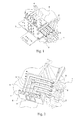
- the electrical connection device according to the invention is shown in FIGS. Figures 1 to 3 is intended to be mounted for example on or in the vicinity of a steering column of a vehicle.
- the electrical connection device makes it possible to electrically connecting a contact surface 1 having conductive tracks 2 to a standard electrical connector not shown.
- the contact surface 1 is for example in motion relative to the electrical connection device.
- the movement is in general but not exclusively a rotation.
- the electrical connection device comprises electrical branches 3 electrically insulated from each other. We can refer for example to Figure 2.
- certain electric branches 3 are electrically connected to each other.
- a first electrical connection interface is made with a first end 4 of the electric branches 3, adapted to the mounting of the connector. These first ends 4 are for example intended to engage in the standard electrical connector.
- a second electrical connection interface is made with the seconds ends 5 of the electric branches 3. These second ends 5 have elastic members making a sliding contact with the contact area 1.
- the electrical connection device also comprises a support 6 in plastic material providing mechanical support for electrical branches 3 between them. This is how the electrical connection device conforms to the invention has different technical characteristics to each of these electrical connection interfaces.
- the standard electrical connector not shown is mounted directly on the first ends 4, and without use of an intermediate piece.
- each electrical branch 3 presents a different cross section at both ends 4 and 5.
- the organs elastics are made with the ends 5 having the smallest section cross. The latter is chosen to guarantee their flexibility and a contact optimal with the contact surface 1, which is made to move for make sliding contacts.
- the end 4 of the electric branches advantageously has a larger cross-section to give them rigidity more important mechanics, which allows them to be engaged indirectly in a standard electrical connector.
- each electrical branch 3 is made in one piece.
- the latter is for example obtained by molding or by cutting and stamping.
- the number of component parts of the electrical connection device is therefore very limited and its realization is particularly simple.
- each electrical branch 3 is made in two pieces interconnected by welding or riveting points. It is so possible to connect together parts with a cross-section more important realizing the first ends 4 to be engaged in the standard electrical connector and cross sectional parts less important properties of elasticity and flexibility to ensure sliding contacts.
- the binding areas of the parties components of the electrical branches 3 are advantageously covered by the support 6 made of plastic.
- the support 6 made of plastic material is example a molded part partially covering the electric branches 3 except the ends 4 and 5 of said branches 3.
- FIG. 2 is a simplified representation partially cut away support 6 made of plastic.
- the first electrical interface present advantageously a series of connection terminals made by the first ends 4 projecting out of the support 6 and intended to be engaged in the electrical connector.
- the second ends 5 are preferably flexible blades constituting the elastic members.
- connection terminals made by the ends 4 and the flexible blades made by the second ends 5 of the electrical branches 3 extend in directions having a angular inclination between 30 and 180 °, and preferably close to 90 °.
- the second ends 5 components of the flexible blades therefore extend substantially parallel or slightly inclined relative to the plane of extension of the contact surface 1 and the connection terminals made by the first ends 4, extend substantially orthogonally with respect to the contact surface 1, facilitating the engagement of the electrical connector.
- the angular orientation between the terminals and the flexible blades can be adjusted.
- the support 6 of plastic is split in a first part 7 and a second part 8.
- the first and second parts 7 and 8 are, for example, overmolded respectively on the branches 3 electrical components of the first and second electrical interface link.
- the electrical connection device according to the invention is particularly well suited for its use in steering wheel controls in the environment of the steering columns of vehicles.
- the support 6 and / or the parts 7, 8 can also constitute one or several electronic circuits. Electronic components can also be positioned between the electrical branches to create specific electrical signals.
- the device according to the invention has the advantage of reducing the number of intermediate parts needed to establish links electric.
- Another advantage of the device according to the invention is related to the large number of mechanical configurations and miniaturization that we can consider.
- the device according to the invention also has a robustness increased electrical connection, even in case of miniaturization.
Landscapes
- Steering Controls (AREA)
Priority Applications (2)
| Application Number | Priority Date | Filing Date | Title |
|---|---|---|---|
| EP20030360123 EP1528641B1 (de) | 2003-10-28 | 2003-10-28 | Vorrichtung zur elektrischen Kontaktierung zwischen zwei Elementen in Relativbewegung |
| DE2003608031 DE60308031T2 (de) | 2003-10-28 | 2003-10-28 | Verbindung von Stücken in Relativbewegung |
Applications Claiming Priority (1)
| Application Number | Priority Date | Filing Date | Title |
|---|---|---|---|
| EP20030360123 EP1528641B1 (de) | 2003-10-28 | 2003-10-28 | Vorrichtung zur elektrischen Kontaktierung zwischen zwei Elementen in Relativbewegung |
Publications (2)
| Publication Number | Publication Date |
|---|---|
| EP1528641A1 true EP1528641A1 (de) | 2005-05-04 |
| EP1528641B1 EP1528641B1 (de) | 2006-08-30 |
Family
ID=34400607
Family Applications (1)
| Application Number | Title | Priority Date | Filing Date |
|---|---|---|---|
| EP20030360123 Expired - Lifetime EP1528641B1 (de) | 2003-10-28 | 2003-10-28 | Vorrichtung zur elektrischen Kontaktierung zwischen zwei Elementen in Relativbewegung |
Country Status (2)
| Country | Link |
|---|---|
| EP (1) | EP1528641B1 (de) |
| DE (1) | DE60308031T2 (de) |
Citations (3)
| Publication number | Priority date | Publication date | Assignee | Title |
|---|---|---|---|---|
| US5230713A (en) * | 1990-11-17 | 1993-07-27 | Kabelmetal Electro Gesellschaft Mit Beschrankter Haftung | Device for the transmission of current between two end points |
| US6007344A (en) * | 1995-02-17 | 1999-12-28 | Lear Corporation | Multiple brush steering wheel commutator |
| US6273735B1 (en) * | 2000-10-25 | 2001-08-14 | 3Com Corporation | Rotating turret side-entry retractable jack |
-
2003
- 2003-10-28 EP EP20030360123 patent/EP1528641B1/de not_active Expired - Lifetime
- 2003-10-28 DE DE2003608031 patent/DE60308031T2/de not_active Expired - Lifetime
Patent Citations (3)
| Publication number | Priority date | Publication date | Assignee | Title |
|---|---|---|---|---|
| US5230713A (en) * | 1990-11-17 | 1993-07-27 | Kabelmetal Electro Gesellschaft Mit Beschrankter Haftung | Device for the transmission of current between two end points |
| US6007344A (en) * | 1995-02-17 | 1999-12-28 | Lear Corporation | Multiple brush steering wheel commutator |
| US6273735B1 (en) * | 2000-10-25 | 2001-08-14 | 3Com Corporation | Rotating turret side-entry retractable jack |
Also Published As
| Publication number | Publication date |
|---|---|
| DE60308031D1 (de) | 2006-10-12 |
| EP1528641B1 (de) | 2006-08-30 |
| DE60308031T2 (de) | 2007-04-12 |
Similar Documents
| Publication | Publication Date | Title |
|---|---|---|
| FR3026897A1 (fr) | Connecteur electrique | |
| FR2684492A1 (fr) | Dispositif d'interconnexion electrique. | |
| FR2685560A1 (fr) | Element de connecteur electrique fixable de facon flottante sur un organe de support. | |
| EP1528641B1 (de) | Vorrichtung zur elektrischen Kontaktierung zwischen zwei Elementen in Relativbewegung | |
| EP2940800B1 (de) | Elektrische anschlussvorrichtung zwischen zwei elektronischen karten und deren verbindungsverfahren | |
| EP2745661B1 (de) | Elektrische verbindungsvorrichtung, anordnung mit einer solchen vorrichtung und elektronikplatine sowie verfahren zum elektrischen anschluss einer elektronikplatine | |
| EP3790126B1 (de) | Einheit für steckverbinder, die für eine blindmontage geeignet ist | |
| EP2783423B1 (de) | Verfahren zur plazierung einer elektonischen leiterplatte in kontakt mit mehreren kontaktelementen in einem gehäuse zur aufname oder umschliessung der elektronischen leiterplatte und gehäuse | |
| EP0251909B1 (de) | Verbindungselement für ein elektrisches Monoleiterkabel zur axialen Verbindung | |
| WO2011042283A1 (fr) | Connecteur traversant pour support métallique, pièce isolante et support métallique associés | |
| EP1568109A1 (de) | Elektrischer kontakt mit elastischer rückstellvorrichtung und elektrischem verbindungsteil mit mindestens einem solchen kontakt | |
| FR2683397A1 (fr) | Douille electrique pour interconnecter des circuits sur une puce et des circuits sur un substrat. | |
| FR2951315A1 (fr) | Embase pour relais | |
| FR3040243A1 (fr) | Dispositif de connexion electrique ameliore | |
| FR2843655A1 (fr) | Broche a emmanchement a force | |
| FR3043523A1 (fr) | Dispositif de pilotage de l'alimentation electrique d'un composant electronique pour vehicule automobile | |
| WO2009144231A1 (fr) | Ensemble de connexion électrique étanchéifié | |
| FR2945156A1 (fr) | Cosse de connexion electrique a detrompeur | |
| EP1672740A1 (de) | Schnellverbindungsanschlussklemme für Schalter und Steckdosen | |
| FR2806216A1 (fr) | Dispositif de connexion rapide d'un cable a une borne d'une source d'alimentation en energie electrique | |
| WO2008012428A2 (fr) | Module électronique avec connecteur à pattes élastiques de contact, connecteur et cartes correspondants | |
| FR3088500A1 (fr) | Porte-balais de machine electrique tournante muni d'oeillets integres aux traces conductrices | |
| FR2938113A1 (fr) | Appareil electrique tel qu'un interrupteur | |
| FR3107618A1 (fr) | Connecteur electrique a verrouillage electro-mecanique | |
| FR3087586A1 (fr) | Renvoi d’angle pour conducteurs electriques presentant une articulation verrouillable |
Legal Events
| Date | Code | Title | Description |
|---|---|---|---|
| PUAI | Public reference made under article 153(3) epc to a published international application that has entered the european phase |
Free format text: ORIGINAL CODE: 0009012 |
|
| AK | Designated contracting states |
Kind code of ref document: A1 Designated state(s): AT BE BG CH CY CZ DE DK EE ES FI FR GB GR HU IE IT LI LU MC NL PT RO SE SI SK TR |
|
| AX | Request for extension of the european patent |
Extension state: AL LT LV MK |
|
| 17P | Request for examination filed |
Effective date: 20050625 |
|
| AKX | Designation fees paid |
Designated state(s): DE FR |
|
| GRAP | Despatch of communication of intention to grant a patent |
Free format text: ORIGINAL CODE: EPIDOSNIGR1 |
|
| GRAS | Grant fee paid |
Free format text: ORIGINAL CODE: EPIDOSNIGR3 |
|
| GRAA | (expected) grant |
Free format text: ORIGINAL CODE: 0009210 |
|
| AK | Designated contracting states |
Kind code of ref document: B1 Designated state(s): DE FR |
|
| REF | Corresponds to: |
Ref document number: 60308031 Country of ref document: DE Date of ref document: 20061012 Kind code of ref document: P |
|
| PLBE | No opposition filed within time limit |
Free format text: ORIGINAL CODE: 0009261 |
|
| STAA | Information on the status of an ep patent application or granted ep patent |
Free format text: STATUS: NO OPPOSITION FILED WITHIN TIME LIMIT |
|
| 26N | No opposition filed |
Effective date: 20070531 |
|
| REG | Reference to a national code |
Ref country code: FR Ref legal event code: PLFP Year of fee payment: 13 |
|
| REG | Reference to a national code |
Ref country code: FR Ref legal event code: PLFP Year of fee payment: 14 |
|
| PGFP | Annual fee paid to national office [announced via postgrant information from national office to epo] |
Ref country code: DE Payment date: 20161027 Year of fee payment: 14 Ref country code: FR Payment date: 20161025 Year of fee payment: 14 |
|
| REG | Reference to a national code |
Ref country code: DE Ref legal event code: R119 Ref document number: 60308031 Country of ref document: DE |
|
| REG | Reference to a national code |
Ref country code: FR Ref legal event code: ST Effective date: 20180629 |
|
| PG25 | Lapsed in a contracting state [announced via postgrant information from national office to epo] |
Ref country code: DE Free format text: LAPSE BECAUSE OF NON-PAYMENT OF DUE FEES Effective date: 20180501 |
|
| PG25 | Lapsed in a contracting state [announced via postgrant information from national office to epo] |
Ref country code: FR Free format text: LAPSE BECAUSE OF NON-PAYMENT OF DUE FEES Effective date: 20171031 |