EP1528630B1 - Elektrischer Steckverbinder - Google Patents
Elektrischer Steckverbinder Download PDFInfo
- Publication number
- EP1528630B1 EP1528630B1 EP04025344.5A EP04025344A EP1528630B1 EP 1528630 B1 EP1528630 B1 EP 1528630B1 EP 04025344 A EP04025344 A EP 04025344A EP 1528630 B1 EP1528630 B1 EP 1528630B1
- Authority
- EP
- European Patent Office
- Prior art keywords
- contact members
- plug
- plug connector
- webs
- electric plug
- Prior art date
- Legal status (The legal status is an assumption and is not a legal conclusion. Google has not performed a legal analysis and makes no representation as to the accuracy of the status listed.)
- Expired - Lifetime
Links
- 230000004308 accommodation Effects 0.000 claims description 2
- 230000002093 peripheral effect Effects 0.000 claims description 2
- 239000002184 metal Substances 0.000 description 3
- 238000002788 crimping Methods 0.000 description 1
- 230000037431 insertion Effects 0.000 description 1
- 238000003780 insertion Methods 0.000 description 1
- 238000004519 manufacturing process Methods 0.000 description 1
- 238000003466 welding Methods 0.000 description 1
Images

Classifications
-
- H—ELECTRICITY
- H01—ELECTRIC ELEMENTS
- H01R—ELECTRICALLY-CONDUCTIVE CONNECTIONS; STRUCTURAL ASSOCIATIONS OF A PLURALITY OF MUTUALLY-INSULATED ELECTRICAL CONNECTING ELEMENTS; COUPLING DEVICES; CURRENT COLLECTORS
- H01R13/00—Details of coupling devices of the kinds covered by groups H01R12/70 or H01R24/00 - H01R33/00
- H01R13/02—Contact members
- H01R13/15—Pins, blades or sockets having separate spring member for producing or increasing contact pressure
- H01R13/18—Pins, blades or sockets having separate spring member for producing or increasing contact pressure with the spring member surrounding the socket
-
- H—ELECTRICITY
- H01—ELECTRIC ELEMENTS
- H01R—ELECTRICALLY-CONDUCTIVE CONNECTIONS; STRUCTURAL ASSOCIATIONS OF A PLURALITY OF MUTUALLY-INSULATED ELECTRICAL CONNECTING ELEMENTS; COUPLING DEVICES; CURRENT COLLECTORS
- H01R13/00—Details of coupling devices of the kinds covered by groups H01R12/70 or H01R24/00 - H01R33/00
- H01R13/02—Contact members
- H01R13/20—Pins, blades, or sockets shaped, or provided with separate member, to retain co-operating parts together
-
- H—ELECTRICITY
- H01—ELECTRIC ELEMENTS
- H01R—ELECTRICALLY-CONDUCTIVE CONNECTIONS; STRUCTURAL ASSOCIATIONS OF A PLURALITY OF MUTUALLY-INSULATED ELECTRICAL CONNECTING ELEMENTS; COUPLING DEVICES; CURRENT COLLECTORS
- H01R2201/00—Connectors or connections adapted for particular applications
- H01R2201/26—Connectors or connections adapted for particular applications for vehicles
Definitions
- the present invention relates to an electric plug connector.
- Plug connectors are known that can accommodate a flat plug in two orientations positioned perpendicularly with respect to each other.
- the invention improves an above-mentioned electric plug connector.
- the electric plug connector has two separate contact members, each of the contact members having a first pair of parallel elongate webs spaced from each other and a second pair of elongate webs that extend in the same plane perpendicular to the first pair of webs.
- the first and second contact members are assembled so that the first pairs of webs of both contact members are aligned to define a first flat plug-in channel and the second pairs of webs of both contact members are spaced from each other and face each other to define a second flat plug-in channel perpendicular to and crossing the first plug-in channel.
- the two separate contact members are held in an assembled condition by a holding member tightly surrounding the contact members.
- the holding element is a spring wire. This component is easy to produce, inexpensive and quick to install.
- the use of a metallic ribbon as the holding element entails the same advantages.
- the holding element can be configured elastically to transmit a spring force to the contact surfaces so that a male connector can be held in a springy fashion, or it can be rigid to fix the contact member webs tightly to a contact, e.g. a flat plug.
- the contact members have external cutouts aligned with each other to form a peripheral groove in the assembled condition for accommodation of the holding member.
- this makes possible to create a detachment-proof locking mechanism for a correspondingly shaped male connector, e.g. a flat or cross-shaped plug.
- the male connector has, for example, a lateral groove into which the holding element latches when the male connector is in the correct position.
- the male connector can be a contact pin provided on a board of an electronic device to which the plug connector is connected.
- both plug-in channels form a cruciform cross section so that a flat plug can be accommodated in two different orientations positioned vertically with respect to each other.
- a male connector with a cruciform cross section can be inserted.
- the male connector can be engaged in both plug-in channels.
- the holding element surrounds the contact members in a detachment-proof manner.
- each contact member pair contains two integrally connected segments.
- the contact members can be stamped from a blank and then deformed.
- the contact members are assembled around a male connector partially engaged in at least one of the plug-in channels, the holding member also surrounding and engaging the male connector.
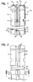
- Figure 1 shows an electric plug connector 10 that consists of four segments 12.
- the four segments 12 are essentially identical.
- Each segment 12 has an angled contact section 14 at the upper longitudinal end 13 (in the figures) as well as at the lower longitudinal end 15 (in the figures).
- Two adjoining segments 12 each form a first and a second contact member pair 17a, 17b.
- the segments 12 are integrally connected via bridges 11 arranged between the upper and lower contact surfaces 16.
- Each bridge 11 has a slit at the side directed towards the lower longitudinal end 15.
- Two segments 12 each are jointly stamped from a sheet metal and formed to one contact member pair 17a, 17b. Both contact members 17a, 17b are substantially identical.
- Each contact member pair 17a, 17b has a first pair of parallel elongate webs spaced from each other and a second pair of elongate webs extending in the same plane as the first and perpendicular to the first pair of webs, each web forming a contact surface 16.
- the contact members 17a, 17b are assembles so that the first pairs of webs of both contact members are aligned to define a first flat plug-in channel, which is given the reference number 18a in Figure 3 .
- the second webs of both contact members 17a, 17b are spaced from each other and face each other to define a second flat plug-in channel 18b perpendicular to and crossing the first plug-in channel 18a.
- the designation of the plug-in channels 18a, 18b and therewith of the first and second pair of webs of each contact member pair 17a, 17b in figure 3 is arbitrarily chosen and could be reversed.
- Both plug-in channels 18a, 18b together form a plug-in channel 18 that has a cruciform cross section, that runs parallel to the lengthwise extension of the contact sections 14 and is delimited by the contact surfaces 16.
- the webs are provided at the upper and lower longitudinal end of the contact members 17a, 17b, respectively, so that plug-in channels 18, 18a, 18b are provided at each longitudinal end 13, 15 of the plug connector 10.
- the contact surfaces 16 serve to establish the electric contact between the male connector 24 and the plug connector 10.
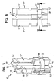
- a male connector 24 with a cruciform cross section as is shown in Figure 3 .
- the male connector 24 is e.g. a contact pin arranged on a board of a electronic device.
- the plug-in channels 18 at both longitudinal ends 13, 15 can accommodate both a flat plug (shown in broken lines in Figure 3 ) and a male connector 24 with a cruciform section.
- the two contact members 17a, 17b are connected by a holding element 20 that is separate from the contact members 17a, 17b.
- the individual contact members 17a, 17b are joined to each other here only via the holding element 20. Further connections, for example, made by welding, can be dispensed with.
- the holding element 20 holds the contact members 17a, 17b together in a detachment-proof manner.
- the holding element 20 is a spring wire that has a predefined elasticity.
- the force can be directly determined with which a plug inserted into the plug-in channel 18 is held by the contact surfaces 16.
- the holding element 20 is arranged in the area of the lower longitudinal end 15 of the plug connector 10. In certain sections, the holding element 20 lies in each segment 12 in a section 22 provided there that passes through the wall of the contact section 14 so that the holding element 20 projects into the plug-in channel 18. The holding element 20 thus lies in a circumferential groove formed on the segments 12.
- the holding element 20 here concurrently serves as a detachment-proof locking mechanism.
- the elasticity of the spring wire is utilized for this purpose.
- the narrow sides of the male connector 24 each have a groove 26 and the male connector 24 is provided with sliding surfaces 28 on its insertion end 27. The sliding surfaces 28 push the holding element 20 apart when the male connector 24 is inserted into the plug-in channel 18. As soon as the grooves 26 have reached the holding element 20, the latter snaps back and holds the male connector 24 in place.
- a conventional flat plug can be inserted into one of the plug-in channels 18, 18a, 18b located at the upper longitudinal end 13 of the plug connector 10.
- a holding element 20 is provided only at the lower longitudinal end 15 of the plug connector 10. It would also be possible to provide a holding element 20 at the upper longitudinal end 13 and/or in the middle of the plug connector 10. It would also be conceivable to use several holding elements 20.
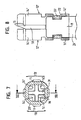
- a second embodiment is shown in Figures 5 to 8 .
- the plug connector 10' likewise consists of four individual segments 12' forming two contact members 17a', 17b'.
- the segments 12 forming each contact member pair 17a', 17b' are connected integrally via a bridge 11.
- the two contact members 17a', 17b' are joined to each other only via a separate holding element 20'.
- the holding element 20' is made of a rigid metal ribbon.
- the holding element 20' is arranged in the area of the lower longitudinal end 15 of the plug connector 10', namely, in such a way that it projects into the cutouts 22 into angled contact sections 14' leading into the plug-in channel 18.
- the two contact members 17a', 17b' are assembled around the male connector 24 and then encircled by the holding member 20' and in this way fixedly and non-elastically connected to the male connector 24.
- the metal ribbon can be attached to the plug connector 10' by crimping.
- the contact sections 14' are not configured to be angular in shape but rather consist of four plates arranged in pairs in the same orientation next to each other.
Landscapes
- Coupling Device And Connection With Printed Circuit (AREA)
- Details Of Connecting Devices For Male And Female Coupling (AREA)
- Multi-Conductor Connections (AREA)
Claims (8)
- Elektrischer Steckverbinder mit zwei getrennten Kontaktelementen (17a, 17b; 17a', 17b'), wobei die Kontaktelemente (17a, 17b; 17a', 17b') jeweils ein erstes Paar paralleler langgestreckter, voneinander beabstandeter Stege und ein zweites Paar langgestreckter Stege aufweisen, die sich in der gleichen Ebene senkrecht zu dem ersten Paar Stege erstrecken, wobei die ersten und die zweiten Kontaktelemente (17a, 17b; 17a', 17b') so zusammengesetzt sind, dass die ersten Paare Stege beider Kontaktelemente (17a, 17b; 17a', 17b') so ausgerichtet sind, dass ein erster flacher Steckkanal (18a) gebildet ist, und die zweiten Paare Stege beider Kontaktelemente so voneinander beabstandet und einander zugewandt sind, dass ein zweiter flacher Steckkanal (18b) gebildet ist, der senkrecht zum ersten Steckkanal (18a) ist und diesen kreuzt, wobei die zwei getrennten Kontaktelemente (17a, 17b; 17a', 17b') von einem Halteelement (20; 20'), das die Kontaktelemente (17a, 17b; 17a', 17b') eng umschließt, in einem zusammengesetzten Zustand gehalten sind.
- Elektrischer Steckverbinder nach Anspruch 1, bei dem das Halteelement (20) ein Federdraht ist.
- Elektrischer Steckverbinder nach Anspruch 1, bei dem das Halteelement (20') ein Metallband ist.
- Elektrischer Steckverbinder nach Anspruch 1, bei dem die Kontaktelemente (17a, 17b; 17a', 17b') äußere Ausschnitte aufweisen, die so aufeinander ausgerichtet sind, dass sie im zusammengesetzten Zustand eine Umfangsnut zur Aufnahme des Halteelements (20; 20') bilden.
- Elektrischer Steckverbinder nach Anspruch 1, bei dem jedes Kontaktelement (17a, 17b; 17a', 17b') zwei einstückig miteinander verbundene Segmente (12) enthält, wobei jedes Segment (12) einen aus dem ersten Paar langgestreckter Stege und einen aus dem zweiten Paar langgestreckter Stege aufweist.
- Elektrischer Steckverbinder nach Anspruch 1, bei dem die Kontaktelemente (17a, 17b; 17a', 17b') aus einem Rohling ausgestanzt sind.
- Elektrischer Steckverbinder nach Anspruch 1, bei dem die Kontaktelemente (17a, 17b; 17a', 17b') um einen Stecker (24) zusammengesetzt sind, der teilweise in wenigstens einen der Steckkanäle (18) eingreift, wobei das Halteelement (20; 20') auch den Stecker (24) umschließt und daran anliegt.
- Elektrischer Steckverbinder nach Anspruch 7, bei dem der Stecker (24) im Querschnitt kreuzförmig ist und in beide Steckkanäle (18a, 18b) eingreift.
Applications Claiming Priority (2)
| Application Number | Priority Date | Filing Date | Title |
|---|---|---|---|
| DE10351099A DE10351099B3 (de) | 2003-10-31 | 2003-10-31 | Elektrischer Steckverbinder |
| DE10351099 | 2003-10-31 |
Publications (4)
| Publication Number | Publication Date |
|---|---|
| EP1528630A2 EP1528630A2 (de) | 2005-05-04 |
| EP1528630A3 EP1528630A3 (de) | 2006-03-01 |
| EP1528630B1 true EP1528630B1 (de) | 2014-03-26 |
| EP1528630B8 EP1528630B8 (de) | 2014-05-21 |
Family
ID=34399641
Family Applications (1)
| Application Number | Title | Priority Date | Filing Date |
|---|---|---|---|
| EP04025344.5A Expired - Lifetime EP1528630B8 (de) | 2003-10-31 | 2004-10-25 | Elektrischer Steckverbinder |
Country Status (5)
| Country | Link |
|---|---|
| US (1) | US7033232B2 (de) |
| EP (1) | EP1528630B8 (de) |
| JP (1) | JP4119878B2 (de) |
| CN (1) | CN100388569C (de) |
| DE (1) | DE10351099B3 (de) |
Families Citing this family (5)
| Publication number | Priority date | Publication date | Assignee | Title |
|---|---|---|---|---|
| DE102006062022B4 (de) * | 2006-12-29 | 2022-05-25 | Te Connectivity Germany Gmbh | Elektrischer Kreuzkontakt |
| CN102496537A (zh) * | 2011-12-21 | 2012-06-13 | 宁波华德汽车零部件有限公司 | 一种汽车保险丝盒用连接端子 |
| US20140192457A1 (en) * | 2013-01-10 | 2014-07-10 | Tyco Electronics Corporation | Battery distribution unit |
| DE102020101836A1 (de) | 2020-01-27 | 2021-07-29 | Lisa Dräxlmaier GmbH | Fixiereinrichtung für elektrische kontaktpartner |
| DE102023100390A1 (de) * | 2023-01-10 | 2024-07-11 | Phoenix Contact Gmbh & Co. Kg | Kontaktelement und Verfahren zum Fertigen eines Kontaktelements |
Family Cites Families (17)
| Publication number | Priority date | Publication date | Assignee | Title |
|---|---|---|---|---|
| DE22729C (de) | R. RÖSSLER und A. RÖSS-LER in Gablonz a. N. Böhmen | Bernstein-Imitation und Verfahren zu deren Herstellung | ||
| JPS5077764U (de) * | 1973-11-19 | 1975-07-05 | ||
| US4497527A (en) * | 1982-09-30 | 1985-02-05 | Raychem Corporation | Supplementary force heat-recoverable connecting device |
| EP0322642A3 (de) * | 1987-12-27 | 1990-11-14 | Ichiemon Shosha Company Ltd. | Steckverbinder |
| JPH0745900Y2 (ja) * | 1987-12-27 | 1995-10-18 | 株式会社市右衛門商社 | 接続装置のソケット |
| JPH01121272U (de) * | 1988-02-10 | 1989-08-17 | ||
| JPH028880U (de) * | 1988-07-01 | 1990-01-19 | ||
| US4969824A (en) * | 1989-07-28 | 1990-11-13 | Amp Incorporated | Electrical connector |
| US5013267A (en) * | 1990-02-08 | 1991-05-07 | Kabushiki Kaisha Shinko | Electric connector |
| US5092781A (en) * | 1990-11-08 | 1992-03-03 | Amp Incorporated | Electrical connector using shape memory alloy coil springs |
| FR2689690B1 (fr) * | 1992-04-07 | 1994-07-08 | Electricfil | Cosse femelle de connexion electrique pour borne de raccordement. |
| JPH0668364U (ja) * | 1993-02-26 | 1994-09-22 | 和泉電気株式会社 | 接続具 |
| FR2710461B1 (fr) * | 1993-09-21 | 1995-11-24 | Matra Marconi Space France | Dispositif de connexion électrique embrochable. |
| JP2542339B2 (ja) * | 1994-03-09 | 1996-10-09 | 中部電力株式会社 | 多相一括差込み接続器 |
| GB9409238D0 (en) * | 1994-05-10 | 1994-06-29 | Amp Gmbh | Universal contact receptacle |
| US6533617B1 (en) * | 2000-01-07 | 2003-03-18 | J. D'addario & Company, Inc. | Electrical plug connectors |
| DE10019241A1 (de) * | 2000-04-18 | 2001-10-25 | Grote & Hartmann | Elektrisches Kontaktelement |
-
2003
- 2003-10-31 DE DE10351099A patent/DE10351099B3/de not_active Expired - Fee Related
-
2004
- 2004-10-25 EP EP04025344.5A patent/EP1528630B8/de not_active Expired - Lifetime
- 2004-10-28 US US10/975,135 patent/US7033232B2/en not_active Expired - Lifetime
- 2004-10-29 JP JP2004315061A patent/JP4119878B2/ja not_active Expired - Fee Related
- 2004-10-29 CN CNB2004100901767A patent/CN100388569C/zh not_active Expired - Fee Related
Also Published As
| Publication number | Publication date |
|---|---|
| EP1528630A2 (de) | 2005-05-04 |
| CN1612428A (zh) | 2005-05-04 |
| US20050124230A1 (en) | 2005-06-09 |
| JP4119878B2 (ja) | 2008-07-16 |
| JP2005135915A (ja) | 2005-05-26 |
| CN100388569C (zh) | 2008-05-14 |
| US7033232B2 (en) | 2006-04-25 |
| EP1528630A3 (de) | 2006-03-01 |
| EP1528630B8 (de) | 2014-05-21 |
| DE10351099B3 (de) | 2005-08-25 |
Similar Documents
| Publication | Publication Date | Title |
|---|---|---|
| JP4804386B2 (ja) | プレスフィット・コンタクト | |
| US5800186A (en) | Printed circuit board assembly | |
| US6736683B2 (en) | Electrical terminal | |
| US6368128B1 (en) | Electrical plug-in cable connector with short-circuit bypass | |
| EP0419031A1 (de) | Elektrischer Anzapfstecker | |
| US5683267A (en) | Electrical contact element | |
| US4452504A (en) | Cross connection link for establishing the same phase between electrical terminal blocks | |
| EP0191539A2 (de) | Elektrisches Anschlussendstück für Steckverbinder | |
| JP2008041667A (ja) | 導電体のための接続コンタクト | |
| EP0227153A1 (de) | Verbinder zum Verbinden eines Kabels mit einer gedruckten Leiterplatte oder einem Kontaktstiftträger | |
| EP1528630B1 (de) | Elektrischer Steckverbinder | |
| US7503766B2 (en) | Blocking device for preventing board connector mismating | |
| EP0684756A2 (de) | Fassung mit einer elektrischen Nebenvorrichtung | |
| JP4431674B2 (ja) | 基板間コネクタ | |
| US5199909A (en) | Contact socket for connecting flat contact tongues | |
| EP0741918B1 (de) | Chipkartenverbinder | |
| JP4558406B2 (ja) | 印刷回路基板用プラグコンタクト | |
| KR20000070250A (ko) | 릴레이 소켓 | |
| US6254405B1 (en) | Electrical connector | |
| US5509819A (en) | Low profile splice bussing plate | |
| JP4266776B2 (ja) | プラグイン接触子及びプラグイン接触子の接続構造 | |
| JP3537740B2 (ja) | 電気コネクタ組立体 | |
| US11349239B2 (en) | Terminal with offset connection section | |
| EP0214059A2 (de) | Kontakthaltestruktur für Steckverbinder | |
| EP0060024A1 (de) | Elektrische Buchse |
Legal Events
| Date | Code | Title | Description |
|---|---|---|---|
| PUAI | Public reference made under article 153(3) epc to a published international application that has entered the european phase |
Free format text: ORIGINAL CODE: 0009012 |
|
| AK | Designated contracting states |
Kind code of ref document: A2 Designated state(s): AT BE BG CH CY CZ DE DK EE ES FI FR GB GR HU IE IT LI LU MC NL PL PT RO SE SI SK TR |
|
| AX | Request for extension of the european patent |
Extension state: AL HR LT LV MK |
|
| PUAL | Search report despatched |
Free format text: ORIGINAL CODE: 0009013 |
|
| AK | Designated contracting states |
Kind code of ref document: A3 Designated state(s): AT BE BG CH CY CZ DE DK EE ES FI FR GB GR HU IE IT LI LU MC NL PL PT RO SE SI SK TR |
|
| AX | Request for extension of the european patent |
Extension state: AL HR LT LV MK |
|
| 17P | Request for examination filed |
Effective date: 20060821 |
|
| AKX | Designation fees paid |
Designated state(s): CZ DE FR GB IT |
|
| GRAP | Despatch of communication of intention to grant a patent |
Free format text: ORIGINAL CODE: EPIDOSNIGR1 |
|
| INTG | Intention to grant announced |
Effective date: 20131025 |
|
| GRAS | Grant fee paid |
Free format text: ORIGINAL CODE: EPIDOSNIGR3 |
|
| GRAA | (expected) grant |
Free format text: ORIGINAL CODE: 0009210 |
|
| AK | Designated contracting states |
Kind code of ref document: B1 Designated state(s): CZ DE FR GB IT |
|
| REG | Reference to a national code |
Ref country code: GB Ref legal event code: FG4D |
|
| RAP2 | Party data changed (patent owner data changed or rights of a patent transferred) |
Owner name: TRW AUTOMOTIVE ELECTRONICS & COMPONENTS GMBH |
|
| REG | Reference to a national code |
Ref country code: DE Ref legal event code: R082 Ref document number: 602004044665 Country of ref document: DE Representative=s name: PRINZ & PARTNER PATENTANWAELTE RECHTSANWAELTE, DE Ref country code: DE Ref legal event code: R082 Ref document number: 602004044665 Country of ref document: DE Representative=s name: PRINZ & PARTNER MBB PATENTANWAELTE RECHTSANWAE, DE |
|
| REG | Reference to a national code |
Ref country code: DE Ref legal event code: R096 Ref document number: 602004044665 Country of ref document: DE Effective date: 20140508 |
|
| REG | Reference to a national code |
Ref country code: DE Ref legal event code: R097 Ref document number: 602004044665 Country of ref document: DE |
|
| PGFP | Annual fee paid to national office [announced via postgrant information from national office to epo] |
Ref country code: FR Payment date: 20141017 Year of fee payment: 11 Ref country code: GB Payment date: 20141027 Year of fee payment: 11 Ref country code: CZ Payment date: 20141010 Year of fee payment: 11 |
|
| PLBE | No opposition filed within time limit |
Free format text: ORIGINAL CODE: 0009261 |
|
| STAA | Information on the status of an ep patent application or granted ep patent |
Free format text: STATUS: NO OPPOSITION FILED WITHIN TIME LIMIT |
|
| 26N | No opposition filed |
Effective date: 20150106 |
|
| PGFP | Annual fee paid to national office [announced via postgrant information from national office to epo] |
Ref country code: IT Payment date: 20141028 Year of fee payment: 11 |
|
| REG | Reference to a national code |
Ref country code: DE Ref legal event code: R097 Ref document number: 602004044665 Country of ref document: DE Effective date: 20150106 |
|
| PGFP | Annual fee paid to national office [announced via postgrant information from national office to epo] |
Ref country code: DE Payment date: 20151028 Year of fee payment: 12 |
|
| GBPC | Gb: european patent ceased through non-payment of renewal fee |
Effective date: 20151025 |
|
| PG25 | Lapsed in a contracting state [announced via postgrant information from national office to epo] |
Ref country code: CZ Free format text: LAPSE BECAUSE OF NON-PAYMENT OF DUE FEES Effective date: 20151025 Ref country code: GB Free format text: LAPSE BECAUSE OF NON-PAYMENT OF DUE FEES Effective date: 20151025 Ref country code: IT Free format text: LAPSE BECAUSE OF NON-PAYMENT OF DUE FEES Effective date: 20151025 |
|
| REG | Reference to a national code |
Ref country code: FR Ref legal event code: ST Effective date: 20160630 |
|
| PG25 | Lapsed in a contracting state [announced via postgrant information from national office to epo] |
Ref country code: FR Free format text: LAPSE BECAUSE OF NON-PAYMENT OF DUE FEES Effective date: 20151102 |
|
| REG | Reference to a national code |
Ref country code: DE Ref legal event code: R119 Ref document number: 602004044665 Country of ref document: DE |
|
| PG25 | Lapsed in a contracting state [announced via postgrant information from national office to epo] |
Ref country code: DE Free format text: LAPSE BECAUSE OF NON-PAYMENT OF DUE FEES Effective date: 20170503 |