EP1528449A1 - Vorrichtung zum Steuern einer Einrichtung - Google Patents
Vorrichtung zum Steuern einer Einrichtung Download PDFInfo
- Publication number
- EP1528449A1 EP1528449A1 EP05002529A EP05002529A EP1528449A1 EP 1528449 A1 EP1528449 A1 EP 1528449A1 EP 05002529 A EP05002529 A EP 05002529A EP 05002529 A EP05002529 A EP 05002529A EP 1528449 A1 EP1528449 A1 EP 1528449A1
- Authority
- EP
- European Patent Office
- Prior art keywords
- axis
- guide element
- elements
- guide
- holding arm
- Prior art date
- Legal status (The legal status is an assumption and is not a legal conclusion. Google has not performed a legal analysis and makes no representation as to the accuracy of the status listed.)
- Granted
Links
- 230000033001 locomotion Effects 0.000 claims description 28
- 230000005540 biological transmission Effects 0.000 claims description 4
- 230000001276 controlling effect Effects 0.000 claims 2
- 230000001771 impaired effect Effects 0.000 claims 1
- 230000001105 regulatory effect Effects 0.000 claims 1
- 238000009434 installation Methods 0.000 description 4
- 239000004677 Nylon Substances 0.000 description 1
- 150000001875 compounds Chemical class 0.000 description 1
- 238000010276 construction Methods 0.000 description 1
- 238000005516 engineering process Methods 0.000 description 1
- 230000002349 favourable effect Effects 0.000 description 1
- 239000007788 liquid Substances 0.000 description 1
- 239000000463 material Substances 0.000 description 1
- 239000002184 metal Substances 0.000 description 1
- 229920001778 nylon Polymers 0.000 description 1
Images


Classifications
-
- G—PHYSICS
- G05—CONTROLLING; REGULATING
- G05G—CONTROL DEVICES OR SYSTEMS INSOFAR AS CHARACTERISED BY MECHANICAL FEATURES ONLY
- G05G9/00—Manually-actuated control mechanisms provided with one single controlling member co-operating with two or more controlled members, e.g. selectively, simultaneously
- G05G9/02—Manually-actuated control mechanisms provided with one single controlling member co-operating with two or more controlled members, e.g. selectively, simultaneously the controlling member being movable in different independent ways, movement in each individual way actuating one controlled member only
- G05G9/04—Manually-actuated control mechanisms provided with one single controlling member co-operating with two or more controlled members, e.g. selectively, simultaneously the controlling member being movable in different independent ways, movement in each individual way actuating one controlled member only in which movement in two or more ways can occur simultaneously
- G05G9/047—Manually-actuated control mechanisms provided with one single controlling member co-operating with two or more controlled members, e.g. selectively, simultaneously the controlling member being movable in different independent ways, movement in each individual way actuating one controlled member only in which movement in two or more ways can occur simultaneously the controlling member being movable by hand about orthogonal axes, e.g. joysticks
- G05G2009/04703—Mounting of controlling member
- G05G2009/04714—Mounting of controlling member with orthogonal axes
- G05G2009/04718—Mounting of controlling member with orthogonal axes with cardan or gimbal type joint
-
- Y—GENERAL TAGGING OF NEW TECHNOLOGICAL DEVELOPMENTS; GENERAL TAGGING OF CROSS-SECTIONAL TECHNOLOGIES SPANNING OVER SEVERAL SECTIONS OF THE IPC; TECHNICAL SUBJECTS COVERED BY FORMER USPC CROSS-REFERENCE ART COLLECTIONS [XRACs] AND DIGESTS
- Y10—TECHNICAL SUBJECTS COVERED BY FORMER USPC
- Y10T—TECHNICAL SUBJECTS COVERED BY FORMER US CLASSIFICATION
- Y10T74/00—Machine element or mechanism
- Y10T74/20—Control lever and linkage systems
- Y10T74/20012—Multiple controlled elements
- Y10T74/20018—Transmission control
- Y10T74/2003—Electrical actuator
-
- Y—GENERAL TAGGING OF NEW TECHNOLOGICAL DEVELOPMENTS; GENERAL TAGGING OF CROSS-SECTIONAL TECHNOLOGIES SPANNING OVER SEVERAL SECTIONS OF THE IPC; TECHNICAL SUBJECTS COVERED BY FORMER USPC CROSS-REFERENCE ART COLLECTIONS [XRACs] AND DIGESTS
- Y10—TECHNICAL SUBJECTS COVERED BY FORMER USPC
- Y10T—TECHNICAL SUBJECTS COVERED BY FORMER US CLASSIFICATION
- Y10T74/00—Machine element or mechanism
- Y10T74/20—Control lever and linkage systems
- Y10T74/20012—Multiple controlled elements
- Y10T74/20201—Control moves in two planes
Definitions
- the present invention relates to a device for Controlling a device, such as aircraft, Airplane simulator, robot od. Like., With a handle, which about two mutually perpendicular axes is movable.
- Such devices are in a variety of forms and Version known and used in the market. she serve primarily to control an aircraft, Flight simulator, robot od. Like. Element.
- a handle is essentially about two axes pivotable about a control of a corresponding To set up.
- a disadvantage of conventional devices is that these are extremely large and complex, if this For example, with drive motors for the corresponding two Movement axes are equipped to a movement of the Follow track and / or control. In addition are These facilities are far too complex and expensive, so that they find only limited use and application.
- WO 81/02208 a device for controlling Liquid transport devices described. These Device has a joystick, which by two staggered axes is movable.
- US 4,520,355 describes a joystick, which with a plurality of potentiometers in the respective axes is provided to have a corresponding twist angle to generate a signal.
- EP 0 151 479 describes a Joystick, which strain gauges are assigned. If the joystick is moved, then the Motion measuring signals displayed on a screen are representable.
- US 4,772,836 discloses a motorized electric described control device for stabilized weapons in a tank, in particular for moving pipes of Machine guns of tanks. It becomes a movement a joystick via externally connected motors braked.
- the present invention is based on the object To provide device of the type mentioned, which eliminates the disadvantages mentioned and with which simple and inexpensive way a device for exact taxation of facilities of all kinds is possible.
- the two guide elements can be inside Drive elements, drive motors include, which the Support movement of the handle and, if necessary computer-controlled and forced, so that a appropriate movement is not carried out too fast.
- Such a device offers many things Applications, especially in the air and Aerospace. However, the invention should not be limited to these Application be limited.
- an inventive Device to any devices, flight simulators, Robot od. Like. Use.
- a robot for example, as a surgical aid possible.
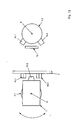
- an apparatus R 1 has a housing 1 in which a first guide element 3.1 is arranged so as to be rotatable about an axis A on an end wall 2.
- the guide element 3.1 is connected to a drive device 4.1, in particular a preferably electrically operated Drive motor 5.1 and a subsequent transmission 6.1 in Compound, as shown in more detail in Figures 3 and 4 is.
- a drive device 4.1 in particular a preferably electrically operated Drive motor 5.1 and a subsequent transmission 6.1 in Compound, as shown in more detail in Figures 3 and 4 is.
- the guide element 3.1 has in the preferred Embodiment, a holding arm 7, which from the A axis approximately at right angles by means of a holding plate. 8 runs out and with it approximately at right angles then receiving plate 9 a right angle forms.
- the receiving plate 9 extends approximately parallel to Axis A.
- On the receiving plate 9 is preferably at right angles to A axis A a second guide element 3.2 stored, which via a second drive device 4.2, in particular Drive motor 5.2 is rotatably mounted about the axis B.
- the handle 10 and / or the guide element 3.2 can at least one force sensor 11.1, 11.2 be assigned, as it is shown in particular in Figures 1 to 3.
- the force sensor 11.1, 11.2 has the task at a manually moving the handle 10 a force and a Detecting movement direction to a forced leadership or also a supported movement of the handle 10 in FIG the respective desired direction by appropriate Twisting the guide elements 3.1, 3.2 by means of Drive devices 4.1, 4.2 allow.
- the embodiment of the present shows Invention according to Figure 5, that the guide element 3.1 via Bearing elements 13 mounted relative to the housing 1 on one side is.
- bearing elements 13 can be used so that the guide element 3.1 on one side about the axis A rotatable relative to the housing. 1 can be stored.
- the bearing elements 13 can be large Absorb forces.
- the guide element 3.1 closes as its component the holding arm 7 at an angle. It sits the guide element 3.1 the holding plate 8, to which eccentric to the axis A and approximately parallel to the axis A, the receiving plate. 9 adjoined. There bearing elements 14 are arranged, which is the Guide element 3.2 rotatable and pivotable about the axis B store.
- a device R 2 is shown in which essentially all the components described above are included according to FIGS. 1 to 5. It is different that the guide element 3.2 with integrated drive device 4.2 at both ends is rotatably mounted relative to the support arm 7 via additional bearing elements 14 about the axis B. A two-sided storage is realized here. For this purpose, another receiving plate 9 adjoins the holding plate 8 at the other end.
- a device R 3 is shown, in which according to the embodiment according to Figure 6, although the guide elements 3.2 are mounted on both sides about the axis B, but the support arm 7 not only at one end on the bearing elements 13 but also at the other end via further bearing elements 13, as schematically indicated here about the axis A is rotatably mounted. At a two-sided storage is thought here.
- a device R 4 is shown, in which the guide element 3.2 according to the embodiment of the device R 1 according to Figure 5 is mounted on one side about the axis B rotatable.
- the retaining arm 7 rotatable on both sides about the axis A, as schematically indicated, stored on the other bearing elements 13. Also, this type of storage is intended by the present Be inventive thought includes.
- a device R 5 is shown, which substantially corresponds to its structure of the device according to Figures 1 to 4.
- Stopperlemente 16.1, 16.2 can control the movement of the Limit guide element 3.1, 3.2. Close this frontally to the guide element 3.2.
- stop element 15.1 and stopper element 16.1, 16.2 approximately close to the axis A. arranged within the holding plate 8 of the holding arm 7.
- another stop element 15.2 is preferably fixed to the end wall 2 of the housing 1, with the both radially to the support plate 8 of the retaining arm.
- 7 Rear side arranged stopper elements 16.3, 16.4 a Direction of movement of the guide element 3.1 about the axis A. to restrict.
- the operation of the device R 5 is shown schematically as a plan view.
- the movement of the guide element 3.1, about the axis A by the stop element 15.2 which end side of the holding plate 8 and / or the receiving plate 9 is arranged opposite two arranged on the end wall 2 of the housing 1 stopper elements 16.3, 16.4, as well as in Figure 12th shown limited.
- the stopper elements 16.1 to 16.4 have corresponding adjusting devices to a limit exact stop accordingly.
- the stopper elements 16.1 to 16.4 as well as the Stop elements 15.1, 15.2 can be made of nylon, metal od. Like. Materials also be made in combination. It is also thought of the corresponding SLOPPER elements 16.1 to 16.4 to dampen a hitting one Dampen stop.
Landscapes
- Physics & Mathematics (AREA)
- General Physics & Mathematics (AREA)
- Engineering & Computer Science (AREA)
- Automation & Control Theory (AREA)
- Toys (AREA)
- Manipulator (AREA)
- Mechanical Control Devices (AREA)
- Transmission Devices (AREA)
Abstract
Description
| Positionszahlenliste | |||||
| 1 | Gehäuse | 34 | 67 | ||
| 2 | Stirnwand | 35 | 68 | ||
| 3 | Führungselement | 36 | 69 | ||
| 4 | Antriebseinrichtung | 37 | 70 | ||
| 5 | Antriebsmotor | 38 | 71 | ||
| 6 | Getriebe | 39 | 72 | ||
| 7 | Haltearm | 40 | 73 | ||
| 8 | Halteplatte | 41 | 74 | ||
| 9 | Aufnahmeplatte | 42 | 75 | ||
| 10 | Handgriff | 43 | 76 | ||
| 11 | Kraftsensor | 44 | 77 | ||
| 12 | Steuerung | 45 | 78 | ||
| 13 | Lagerelement | 46 | 79 | ||
| 14 | Lagerelement | 47 | |||
| 15 | Anschlagelement | 48 | |||
| 16 | Stopperelement | 49 | |||
| 17 | 50 | R1 | Vorrichtung | ||
| 18 | 51 | R2 | Vorrichtung | ||
| 19 | 52 | R3 | Vorrichtung | ||
| 20 | 53 | R4 | Vorrichtung | ||
| 21 | 54 | R5 | Vorrichtung | ||
| 22 | 55 | ||||
| 23 | 56 | A | Achse | ||
| 24 | 57 | B | Achse | ||
| 25 | 58 | ||||
| 26 | 59 | P | Drehpunkt | ||
| 27 | 60 | ||||
| 28 | 61 | S | Schnittpunkt | ||
| 29 | 62 | ||||
| 30 | 63 | ||||
| 31 | 64 | ||||
| 32 | 65 | ||||
| 33 | 66 |
Claims (12)
- Vorrichtung zum Steuern einer Einrichtung wie bspw. Flugzeug, Flugsimulator, Roboter od. dgl., mit einem Handgriff (10) welcher um zwei senkrecht zueinander stehenden Achsen (A, B) bewegbar ist,
dadurch gekennzeichnet, dass dem Handgriff (10) zumindest ein Kraftsensor (11.1, 11.2) zur Steuerung und/oder Regelung einer Bewegung von Führungselementen (3.1, 3.2) auf den Achsen (A, B) zugeordnet ist und die in den Achsen (A, B) gelagerten Führungselemente (3.1, 3.2) separat über jeweils eine in diesen integrierte Antriebseinrichtung (4.1, 4.2) antreibbar sind. - Vorrichtung nach Anspruch 1, dadurch gekennzeichnet, dass der Handgriff (10) um einen Drehpunkt (P) gelagert ist, welcher einem Schnittpunkt (S) der Achsen (A, B) entspricht, wobei ein Führungselement (3.1) in einem Gehäuse (1) gelagert ist, und ausserhalb des Gehäuses (1) ein winkelig angeordneter Haltearm (7), aussermittig zur Achse (A) vorgesehen ist, an welchen senkrecht zur Achse (A) das zweite Führungselement (3.2) drehbar um die Achse (B) anschliesst, und das erste Führungselement (3.1) über Lagerelemente (13) gegenüber dem Gehäuse (1) einseitig um die Achse (A) verdrehbar gelagert ist.
- Vorrichtung nach wenigstens einem der Ansprüche 1 oder 2, dadurch gekennzeichnet, dass an dem Haltearm (7) senkrecht zur Achse (A) das zweite Führungselement (3.2) drehbar um die Achse (B) anschliesst.
- Vorrichtung nach wenigstens einem der Ansprüche 1 bis 3, dadurch gekennzeichnet, dass die Antriebseinrichtung (4.1, 4.2) einen Antriebsmotor (5.1, 5.2) und ggf. ein Getriebe (6.1, 6.2) aufweist.
- Vorrichtung nach wenigstens einem der Ansprüche 1 bis 4, dadurch gekennzeichnet, dass die Antriebseinrichtungen (4.1, 4.2), Antriebsmotoren (5.1, 5.2), Getriebe (6.1, 6.2) sowie der zumindest eine Kraftsensor (11.1, 11.2) mit einer Steuerung (12) verbunden sind.
- Vorrichtung nach wenigstens einem der Ansprüche 1 bis 5, dadurch gekennzeichnet, dass ein zweites Führungselement (3.2) senkrecht zum ersten Führungselement (3.1) gegenüber dessen Haltearmen (7) über weitere Lagerelemente (14) gelagert ist.
- Vorrichtung nach wenigstens einem der Ansprüche 1 bis 6, dadurch gekennzeichnet, dass das zweite Führungselement (3.2) einseitig am Haltearm (7) aussermittig der Achse (A) um die Achse (B) verdrehbar gelagert ist.
- Vorrichtung nach wenigstens einem der Ansprüche 1 bis 7, dadurch gekennzeichnet, dass der Haltearm (7) beidseitig um die Achse (A) gelagert ist.
- Vorrichtung nach wenigstens einem der Ansprüche 1 bis 8, dadurch gekennzeichnet, dass der Haltearm (7) u-förmig ausgebildet ist, zwischen welchem beidseitig das zweite Führungselement (3.2) aussermittig der Achse (A) um die Achse (B) verdrehbar gelagert ist.
- Vorrichtung nach wenigstens einem der Ansprüche 1 bis 9, dadurch gekennzeichnet, dass der Haltearm (7) beidseitig um die Achse (A) und an diesem beidseitig das zweite Führungselement (3.2) um die Achse (B) verdrehbar gelagert ist.
- Vorrichtung nach wenigstens einem der Ansprüche 1 bis 10, dadurch gekennzeichnet, dass das erste Führungselement (3.1) mit einem Anschlagelement (15.2) gegenüber zumindest einem Stopperelement (16.3, 16.4) um die Achse (A) begrenzt verschwenkbar ist und/oder das zweite Führungselement (3.2) gegenüber zumindest einem Anschlagelement (15.1) mit zumindest einem Stopperelement (16.1, 16.2) um die Achse (B) begrenzt verschwenkbar ist, ohne dass jeweils die Bewegungsfreiheit der anderen Achse (A oder B) begrenzt oder beeinträchtigt und zur Begrenzung der Bewegung des Führungselementes (3.1) um die Achse (A) an einer Aufnahmeplatte (9) des Haltearmes (7) angeordnet ist, wobei zumindest ein entsprechendes Stopperelement (16.3, 16.4) einer Seitenwand (2) des Gehäuses (1) zugeordnet ist.
- Vorrichtung nach Anspruch 11, dadurch gekennzeichnet, dass die Stopperelemente (16.1 bis 16.4) einen Weg der Anschlagelemente (15.1, 15.2) einstellbar begrenzen und ggf. zur Feineinstellung der Endlagen mit einer Justiereinrichtung versehen sind.
Applications Claiming Priority (3)
| Application Number | Priority Date | Filing Date | Title |
|---|---|---|---|
| DE19926784A DE19926784A1 (de) | 1999-06-11 | 1999-06-11 | Vorrichtung zum Steuern einer Einrichtung |
| DE19926784 | 1999-06-11 | ||
| EP00943765A EP1185912B1 (de) | 1999-06-11 | 2000-06-06 | Vorrichtung zum steuern einer einrichtung |
Related Parent Applications (1)
| Application Number | Title | Priority Date | Filing Date |
|---|---|---|---|
| EP00943765A Division EP1185912B1 (de) | 1999-06-11 | 2000-06-06 | Vorrichtung zum steuern einer einrichtung |
Publications (2)
| Publication Number | Publication Date |
|---|---|
| EP1528449A1 true EP1528449A1 (de) | 2005-05-04 |
| EP1528449B1 EP1528449B1 (de) | 2006-03-29 |
Family
ID=7911002
Family Applications (2)
| Application Number | Title | Priority Date | Filing Date |
|---|---|---|---|
| EP00943765A Expired - Lifetime EP1185912B1 (de) | 1999-06-11 | 2000-06-06 | Vorrichtung zum steuern einer einrichtung |
| EP05002529A Expired - Lifetime EP1528449B1 (de) | 1999-06-11 | 2000-06-06 | Vorrichtung zum Steuern einer Einrichtung |
Family Applications Before (1)
| Application Number | Title | Priority Date | Filing Date |
|---|---|---|---|
| EP00943765A Expired - Lifetime EP1185912B1 (de) | 1999-06-11 | 2000-06-06 | Vorrichtung zum steuern einer einrichtung |
Country Status (4)
| Country | Link |
|---|---|
| US (1) | US6708580B1 (de) |
| EP (2) | EP1185912B1 (de) |
| DE (3) | DE19926784A1 (de) |
| WO (1) | WO2000077589A1 (de) |
Families Citing this family (13)
| Publication number | Priority date | Publication date | Assignee | Title |
|---|---|---|---|---|
| DE10258197A1 (de) * | 2002-12-12 | 2004-07-08 | Tonic Fitness Technology, Inc., Hsi Kang | Direkt angetriebene Antriebs-Schwingstangen-Einrichtung ohne Totpunkte |
| DE10305261A1 (de) * | 2003-02-07 | 2004-08-26 | Wittenstein Ag | Vorrichtung zum Steuern eines Fahrzeuges |
| US7701161B2 (en) | 2006-10-02 | 2010-04-20 | Honeywell International Inc. | Motor balanced active user interface assembly |
| GB0714916D0 (en) | 2007-07-31 | 2007-09-12 | Wittenstein Aerospace & Simula | Control device |
| WO2009016361A2 (en) * | 2007-07-31 | 2009-02-05 | Wittenstein Aerospace & Simulation Limited | Control device |
| US8096206B2 (en) * | 2007-12-05 | 2012-01-17 | Liebherr-Aerospace Lindenberg Gmbh | Control device |
| US20090266948A1 (en) * | 2008-04-29 | 2009-10-29 | Honeywell International Inc. | Human-machine interface two axis gimbal mechanism |
| DE202017105886U1 (de) | 2017-09-27 | 2017-11-29 | Spohn & Burkhardt GmbH & Co. KG | Schalteinrichtung |
| CN112870630B (zh) * | 2021-02-04 | 2022-10-04 | 李从宇 | 一种适用于残障人士的神经科用下肢康复训练器 |
| US12158388B2 (en) * | 2021-03-30 | 2024-12-03 | Cae Inc. | Calibration adaptor bracket, apparatus and method |
| DE102022134686A1 (de) * | 2022-12-22 | 2024-06-27 | Inventus Engineering Gmbh | Bedieneinrichtung mit wenigstens einem schwenkbaren Bedienhebel |
| JP2026503636A (ja) * | 2023-01-25 | 2026-01-29 | ビ-エイイ- システムズ パブリック リミテッド カンパニ- | アクティブスロットル装置および制御システム |
| EP4406847A1 (de) * | 2023-01-25 | 2024-07-31 | BAE SYSTEMS plc | Aktive drosselanordnung und steuersystem |
Citations (4)
| Publication number | Priority date | Publication date | Assignee | Title |
|---|---|---|---|---|
| WO1981002208A1 (en) | 1980-01-24 | 1981-08-06 | Olsbergs Hydraulic Ab | A device for controlling the fluid supply to a number of consumers |
| US4520355A (en) | 1981-10-31 | 1985-05-28 | Tektronix, Inc. | Joystick apparatus |
| EP0151479A2 (de) | 1984-02-06 | 1985-08-14 | Siemens Aktiengesellschaft | Steuervorrichtung |
| US4772836A (en) | 1985-09-27 | 1988-09-20 | S.A.M.M. - Societe D'applications Des Machines Motrices | Motorized electric control device |
Family Cites Families (6)
| Publication number | Priority date | Publication date | Assignee | Title |
|---|---|---|---|---|
| US3776058A (en) * | 1972-05-17 | 1973-12-04 | Us Navy | Multi-axis hand controller |
| US4704798A (en) * | 1976-07-06 | 1987-11-10 | Hird Edwin A | Measurement digitizer |
| JP2996930B2 (ja) * | 1997-04-04 | 2000-01-11 | 三和電子株式会社 | ジョイスティックコントローラー |
| DE19818866C1 (de) * | 1998-04-28 | 1999-11-11 | Daimler Chrysler Ag | Wähleinrichtung für ein automatisches Kraftfahrzeuggetriebe |
| US6128971A (en) * | 1998-12-21 | 2000-10-10 | Caterpillar Inc. | Control device |
| US6429849B1 (en) * | 2000-02-29 | 2002-08-06 | Microsoft Corporation | Haptic feedback joystick |
-
1999
- 1999-06-11 DE DE19926784A patent/DE19926784A1/de not_active Withdrawn
-
2000
- 2000-06-06 EP EP00943765A patent/EP1185912B1/de not_active Expired - Lifetime
- 2000-06-06 WO PCT/EP2000/005134 patent/WO2000077589A1/de not_active Ceased
- 2000-06-06 DE DE50012165T patent/DE50012165D1/de not_active Expired - Lifetime
- 2000-06-06 DE DE50012502T patent/DE50012502D1/de not_active Expired - Lifetime
- 2000-06-06 US US10/009,185 patent/US6708580B1/en not_active Expired - Lifetime
- 2000-06-06 EP EP05002529A patent/EP1528449B1/de not_active Expired - Lifetime
Patent Citations (4)
| Publication number | Priority date | Publication date | Assignee | Title |
|---|---|---|---|---|
| WO1981002208A1 (en) | 1980-01-24 | 1981-08-06 | Olsbergs Hydraulic Ab | A device for controlling the fluid supply to a number of consumers |
| US4520355A (en) | 1981-10-31 | 1985-05-28 | Tektronix, Inc. | Joystick apparatus |
| EP0151479A2 (de) | 1984-02-06 | 1985-08-14 | Siemens Aktiengesellschaft | Steuervorrichtung |
| US4772836A (en) | 1985-09-27 | 1988-09-20 | S.A.M.M. - Societe D'applications Des Machines Motrices | Motorized electric control device |
Also Published As
| Publication number | Publication date |
|---|---|
| EP1185912A1 (de) | 2002-03-13 |
| EP1528449B1 (de) | 2006-03-29 |
| EP1185912B1 (de) | 2006-02-01 |
| US6708580B1 (en) | 2004-03-23 |
| DE50012502D1 (de) | 2006-05-18 |
| WO2000077589A1 (de) | 2000-12-21 |
| DE50012165D1 (de) | 2006-04-13 |
| DE19926784A1 (de) | 2000-12-14 |
Similar Documents
| Publication | Publication Date | Title |
|---|---|---|
| DE2301423C3 (de) | Handhabungsgerät | |
| AT507373B1 (de) | Bewegungs- und orientierungssimulator | |
| DE2751579C2 (de) | Motorgetriebener Manipulator | |
| DE102008003543B4 (de) | System und Verfahren zum Verstellen von Steuerflächen für Windkanalmodelle | |
| EP1528449B1 (de) | Vorrichtung zum Steuern einer Einrichtung | |
| EP1152182A1 (de) | Operationsmikroskop | |
| AT502864A2 (de) | Parallelkinematischer roboter | |
| DE202005015434U1 (de) | Steuervorrichtung für ein Luftfahrzeug | |
| DE4041676A1 (de) | Einstellbarer fahrzeugscheinwerfer | |
| EP4376729A1 (de) | Chirurgisches instrument und lenkgetriebe dafür | |
| DE60302802T2 (de) | Transportvorrichtung mit untergeordneter steuerung | |
| DE3442899C1 (de) | Ruderantrieb | |
| EP0096774A2 (de) | Treiber zum selbstzentrierenden Antreiben von langgestrecktem Halbzeug | |
| DE69411370T2 (de) | Einschlaggraviervorrichtung | |
| DE69100246T2 (de) | Steuerorgan. | |
| DE29917818U1 (de) | Vorrichtung zum Steuern einer Einrichtung | |
| DE4434660A1 (de) | Fahrsimulator mit Antriebsvorrichtung für Roll- und Nickbewegungen | |
| DE102008028365A1 (de) | Rotorfluggerät mit einer Steuereinrichtung zum Generieren von Steuerbefehlen | |
| DE69001529T2 (de) | Kontrollvorrichtung. | |
| EP0593791B1 (de) | Vorrichtung zum Verstellen eines zahnärztlichen Gerätes | |
| DE202012000521U1 (de) | Elektronische Schließeinrichtung | |
| DE2221513A1 (de) | Steuerhebelanordnung | |
| DE19937765A1 (de) | Einrichtung zum genauen Positionieren einer Antenne | |
| WO2005032911A1 (de) | Verstellbare lenkspindelanordnung | |
| DE4111950A1 (de) | Gewichtsausgleichssystem |
Legal Events
| Date | Code | Title | Description |
|---|---|---|---|
| PUAI | Public reference made under article 153(3) epc to a published international application that has entered the european phase |
Free format text: ORIGINAL CODE: 0009012 |
|
| AC | Divisional application: reference to earlier application |
Ref document number: 1185912 Country of ref document: EP Kind code of ref document: P |
|
| AK | Designated contracting states |
Kind code of ref document: A1 Designated state(s): DE FR GB IT |
|
| 17P | Request for examination filed |
Effective date: 20050618 |
|
| GRAP | Despatch of communication of intention to grant a patent |
Free format text: ORIGINAL CODE: EPIDOSNIGR1 |
|
| GRAS | Grant fee paid |
Free format text: ORIGINAL CODE: EPIDOSNIGR3 |
|
| AKX | Designation fees paid |
Designated state(s): DE FR GB IT |
|
| GRAA | (expected) grant |
Free format text: ORIGINAL CODE: 0009210 |
|
| AC | Divisional application: reference to earlier application |
Ref document number: 1185912 Country of ref document: EP Kind code of ref document: P |
|
| AK | Designated contracting states |
Kind code of ref document: B1 Designated state(s): DE FR GB IT |
|
| REG | Reference to a national code |
Ref country code: GB Ref legal event code: FG4D Free format text: NOT ENGLISH |
|
| GBT | Gb: translation of ep patent filed (gb section 77(6)(a)/1977) |
Effective date: 20060329 |
|
| REF | Corresponds to: |
Ref document number: 50012502 Country of ref document: DE Date of ref document: 20060518 Kind code of ref document: P |
|
| ET | Fr: translation filed | ||
| PLBE | No opposition filed within time limit |
Free format text: ORIGINAL CODE: 0009261 |
|
| STAA | Information on the status of an ep patent application or granted ep patent |
Free format text: STATUS: NO OPPOSITION FILED WITHIN TIME LIMIT |
|
| 26N | No opposition filed |
Effective date: 20070102 |
|
| PGFP | Annual fee paid to national office [announced via postgrant information from national office to epo] |
Ref country code: FR Payment date: 20090615 Year of fee payment: 10 Ref country code: IT Payment date: 20090624 Year of fee payment: 10 |
|
| PGFP | Annual fee paid to national office [announced via postgrant information from national office to epo] |
Ref country code: GB Payment date: 20090618 Year of fee payment: 10 |
|
| GBPC | Gb: european patent ceased through non-payment of renewal fee |
Effective date: 20100606 |
|
| REG | Reference to a national code |
Ref country code: FR Ref legal event code: ST Effective date: 20110228 |
|
| PG25 | Lapsed in a contracting state [announced via postgrant information from national office to epo] |
Ref country code: IT Free format text: LAPSE BECAUSE OF NON-PAYMENT OF DUE FEES Effective date: 20100606 |
|
| PG25 | Lapsed in a contracting state [announced via postgrant information from national office to epo] |
Ref country code: FR Free format text: LAPSE BECAUSE OF NON-PAYMENT OF DUE FEES Effective date: 20100630 |
|
| PG25 | Lapsed in a contracting state [announced via postgrant information from national office to epo] |
Ref country code: GB Free format text: LAPSE BECAUSE OF NON-PAYMENT OF DUE FEES Effective date: 20100606 |
|
| REG | Reference to a national code |
Ref country code: DE Ref legal event code: R082 Ref document number: 50012502 Country of ref document: DE Representative=s name: PATENTANWAELTE UND RECHTSANWALT DR. WEISS, ARA, DE Ref country code: DE Ref legal event code: R082 Ref document number: 50012502 Country of ref document: DE Representative=s name: PATENTANWAELTE UND RECHTSANWALT WEISS, ARAT & , DE |
|
| REG | Reference to a national code |
Ref country code: DE Ref legal event code: R082 Ref document number: 50012502 Country of ref document: DE Representative=s name: PATENTANWAELTE UND RECHTSANWALT WEISS, ARAT & , DE Ref country code: DE Ref legal event code: R081 Ref document number: 50012502 Country of ref document: DE Owner name: WITTENSTEIN SE, DE Free format text: FORMER OWNER: WITTENSTEIN AG, 97999 IGERSHEIM, DE |
|
| PGFP | Annual fee paid to national office [announced via postgrant information from national office to epo] |
Ref country code: DE Payment date: 20190827 Year of fee payment: 20 |
|
| REG | Reference to a national code |
Ref country code: DE Ref legal event code: R071 Ref document number: 50012502 Country of ref document: DE |