EP1528359A1 - Lasernivelliervorrichtung - Google Patents
Lasernivelliervorrichtung Download PDFInfo
- Publication number
- EP1528359A1 EP1528359A1 EP04025161A EP04025161A EP1528359A1 EP 1528359 A1 EP1528359 A1 EP 1528359A1 EP 04025161 A EP04025161 A EP 04025161A EP 04025161 A EP04025161 A EP 04025161A EP 1528359 A1 EP1528359 A1 EP 1528359A1
- Authority
- EP
- European Patent Office
- Prior art keywords
- laser
- housing
- laser level
- disposed
- level
- Prior art date
- Legal status (The legal status is an assumption and is not a legal conclusion. Google has not performed a legal analysis and makes no representation as to the accuracy of the status listed.)
- Withdrawn
Links
Images

Classifications
-
- G—PHYSICS
- G01—MEASURING; TESTING
- G01C—MEASURING DISTANCES, LEVELS OR BEARINGS; SURVEYING; NAVIGATION; GYROSCOPIC INSTRUMENTS; PHOTOGRAMMETRY OR VIDEOGRAMMETRY
- G01C15/00—Surveying instruments or accessories not provided for in groups G01C1/00 - G01C13/00
- G01C15/002—Active optical surveying means
- G01C15/008—Active optical surveying means combined with inclination sensor
Definitions
- This invention relates generally to laser instruments and specifically to laser levels with additional non-leveling capabilities.
- Laser levels have been used in construction for many years. They typically seek to produce a plane of light for a reference for construction projects. Laser levels have been used for large scale construction projects like commercial excavating, laying foundations, and installing drop ceilings. Laser levels save considerable time during initial layout of a construction job compared to other tools such as beam levels, chalk lines, or torpedo levels. Some examples of jobs where laser levels would be useful include laying tile, mounting cabinets, installing counter tops, and building outdoor decks.
- an improved laser level is employed.
- the laser level disposable on a reference surface includes a housing, a first laser diode disposed within the housing for emitting a first laser beam along a first path, a lens disposed in the first path for converting the first laser beam into a first planar beam, the first planar beam forming a line on the reference surface, and an electronic distance measurement circuit disposed within the housing for measuring distance, said distance measurement circuit including a display for showing the measured distance.
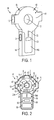
- FIG. 1 is a perspective view of a first embodiment of a laser level according to the invention
- FIG. 2 is a cross-sectional view of the laser level of FIG. 1;
- FIG. 3 illustrates a second embodiment of the laser level, where FIGS. 3A-3B are perspective and cross-sectional views of the laser level, respectively.
- a laser level 10 may have a housing 11.
- the housing 11 may have a top portion 11T and a bottom portion 11B.
- the housing may also have a hole 12 extending through the housing 11.
- the hole 12 preferably extends through the top portion 11T.
- the perimeter of the hole 12 may be defined by an inner wall 11I.
- the top portion 11T may carry a pendulum assembly 30.
- the pendulum assembly 30 has a main body 31, which may be made of metal or plastic. Main body 31 may be disposed on a knife edge 11IK. Knife edge 11IK may be connected to and/or supported by inner wall 11I. Alternatively, knife edge 11IK may be connected to and/or supported by housing 11. Persons skilled in the art will recognize that pendulum assembly 30 may be supported by means other than knife edge 11IK, such as a pin, bearing, point or other pendulous means.
- the main body 31 may carry at least one laser assembly 40 and preferably two laser assemblies 40 disposed left and right of the knife edge 11IK.
- a laser assembly 40 may disposed above knife edge 11IK.
- the laser assemblies 40 will emit laser beams. Accordingly, it is preferable to provide housing 11 with windows 13 to allow the laser beams to exit from housing 11.
- main body 31 may also have weights 33 to provide a lower center of gravity, and enhance the performance of the pendulum assembly 30.
- main body 31 may have at least one adjustment screw 33A to adjust the center of gravity of pendulum assembly 30, as necessary.
- Main body 31 may also have a plaque 33M, made of magnetic material, ferrous material or non-ferrous conductive material, such as zinc or copper.
- Plaque 33M preferably is aligned with at least one magnet (and preferably two magnets) disposed in housing 11, e.g., on the inside of the front and rear walls of housing 11, for providing a damping action on pendulum assembly 30.
- eddie currents are generated within plaque 33M, as the plaque moves and interacts with the magnetic field supplied by the magnet(s).
- pendulum assembly 30 is preferably wholly contained within housing 11. However, the pendulum assembly 30 may be at least partly, if not completely, disposed outside of housing 11.
- the bottom portion 11B of housing 11 may carry a battery 50 for powering the laser assemblies 40.
- the bottom portion 11B may carry a stud sensor circuit 20.
- the circuitry of the stud sensor circuit 20 is not illustrated herein. Persons skilled in the art are referred to U.S. Pat. Nos. 4,099,118 and 4,464,622, which are wholly incorporated herein by reference.
- the stud sensor circuit 20 may include an on/off actuator or switch 21, which can be a push-button type actuator. Stud sensor circuit 20 may also include light emitting diodes 22 to display the location of a stud.
- detector circuits other than stud sensor circuit 20 may be provided in laser level 10.
- these detector circuits can detect features underneath a surface, such as a wall or floor. These features may include pipes or wires. Circuits for pipe and wire detectors, as well as other detector circuits, are well known in the art.
- the housing 11 may be formed from a hard impact resistant, preferably moldable material such as a hard thermoplastic material such as ABS or polystyrene. It is preferable to provide a grip 14 on bottom portion 11B. Grip 14 may be made of a soft or low durometer thermoplastic elastomer. In addition, grip 14 can be formed from any of the so-called “soft-touch” elastomer materials, such as those sold under the tradenames "Santoprene", “Kraton” and “Monprene,” and are preferably adhered or overmolded to the housing 11.
- the bottom portion 11B may also carry an electronic distance measuring circuit 60.
- the circuitry of the distance measuring circuit 60 is not illustrated herein.
- Persons skilled in the art will know that there are two main types of electronic distance measuring systems: those which are laser-based and those which are sound-based. Persons skilled in the art are referred to U.S. Pat. Nos. 4,097,148, 5,262,837, 5,455,669, 5,638,163, 5,949,530, and 6,057,910, which are wholly incorporated herein by reference, which disclose laser-based electronic distance measuring systems. Similarly, persons skilled in the art are referred to U.S. Pat. Nos. 4,451,909,4,464,738, and 4,910,717, which are wholly incorporated herein by reference, which disclose sound-based electronic distance measuring systems.
- a sound or laser transmitter 61 is placed in housing 11.
- the transmitter 61 sends a signal, which contacts the target and bounces back towards the laser level 10.
- This signal is received by a sound or laser receiver 62 placed in housing 11.
- the distance measuring circuit 60 processes the data and calculates the distance, as is well known in the art. The calculated distance can then be displayed on a display 63 disposed on housing 11.
- Laser assembly 40 may include a substantially cylindrical barrel 41, which may be adjustably connected to main body 31, laser diode 42 disposed in barrel 41, and a line lens 43 disposed in barrel 41.
- adjusting barrel 41 will result in moving laser diode 42 and line lens 43.
- a collimating lens may be disposed between laser diode 42 and line lens 43.
- line lens 43 converts the laser beam exiting laser diode 42 into a planar beam.
- laser assembly 40 when laser level 10 is disposed against a wall, laser assembly 40 will preferably emit a laser plane that contacts the wall, forming a laser line on the wall. Persons skilled in the art will recognize that it is preferable to orient the laser assemblies 40 in such manner so that at least a portion of the laser plane will contact the wall. In addition, persons skilled in the art will recognize that providing laser assemblies 40 on the pendulum assembly 30 discussed above will preferably result in laser level 10 projecting substantially horizontal laser lines against the wall (and a substantially vertical laser beam if a laser assembly 40 is disposed above knife edge 11IK and is directed upwardly).
- laser level 10 A second embodiment of laser level 10 is shown in FIG. 3, where like numerals refer to like parts.
- the teachings of the first embodiment above are wholly incorporated by reference in the present embodiment.
- laser level 10 has laser assemblies 40 for projecting laser beams, preferably in the form of planes.
- laser level 10 has a stud sensor circuit 20.
- Laser level 10 may also have an electronic distance measuring circuit 60 as in the previous embodiment.
- the main difference is that the laser assemblies 40 are not disposed on a pendulum. Instead, they are fixedly connected to housing 11. Accordingly, the user can disposed housing 11 at any position against a wall or floor, and two laser lines will be emitted unto the wall or floor.
- a horizontal bubble vial 11HV may be provided on housing 11 to indicate to the user when the laser beams are level, i.e., substantially horizontal.
- a vertical bubble vial 11 VV may be provided on housing 11 to indicate to the user when the laser beams are plumb, i.e., substantially vertical.
- Persons skilled in the art will recognize that other means for detecting and indicating whether the laser beams are plumb or level can be used.
Landscapes
- Physics & Mathematics (AREA)
- Engineering & Computer Science (AREA)
- General Physics & Mathematics (AREA)
- Radar, Positioning & Navigation (AREA)
- Remote Sensing (AREA)
- Optical Radar Systems And Details Thereof (AREA)
- Length Measuring Devices By Optical Means (AREA)
- Photometry And Measurement Of Optical Pulse Characteristics (AREA)
Applications Claiming Priority (2)
| Application Number | Priority Date | Filing Date | Title |
|---|---|---|---|
| US693439 | 1996-08-07 | ||
| US10/693,439 US7027480B2 (en) | 2002-05-31 | 2003-10-24 | Laser level |
Publications (1)
| Publication Number | Publication Date |
|---|---|
| EP1528359A1 true EP1528359A1 (de) | 2005-05-04 |
Family
ID=34423328
Family Applications (1)
| Application Number | Title | Priority Date | Filing Date |
|---|---|---|---|
| EP04025161A Withdrawn EP1528359A1 (de) | 2003-10-24 | 2004-10-22 | Lasernivelliervorrichtung |
Country Status (6)
| Country | Link |
|---|---|
| US (1) | US7027480B2 (de) |
| EP (1) | EP1528359A1 (de) |
| JP (2) | JP2005128019A (de) |
| CN (1) | CN1609554A (de) |
| AU (1) | AU2004222835A1 (de) |
| NZ (1) | NZ548249A (de) |
Cited By (3)
| Publication number | Priority date | Publication date | Assignee | Title |
|---|---|---|---|---|
| WO2010052544A1 (de) * | 2008-11-05 | 2010-05-14 | Gulunov Alexey V | Laserentfernungsmessgerät |
| EP3413017A4 (de) * | 2016-02-06 | 2019-09-04 | Changzhou Huada Kejie Opto-Electro Instrument Co., Ltd. | Lasernivelliergerät |
| US10436584B2 (en) | 2016-05-06 | 2019-10-08 | Milwaukee Electric Tool Corporation | Level with audio and/or visual indicators |
Families Citing this family (17)
| Publication number | Priority date | Publication date | Assignee | Title |
|---|---|---|---|---|
| US20060002233A1 (en) * | 2003-03-09 | 2006-01-05 | Fabrice Malard | Combination tool for aligning, measuring distances and sensing objects under a surface |
| IL169436A0 (en) * | 2005-06-28 | 2007-07-04 | Kapro Ind Ltd | Handheld diy tool |
| NZ538538A (en) * | 2005-02-28 | 2005-06-24 | David John Cook | Improved method of laying a foundation |
| US8269612B2 (en) | 2008-07-10 | 2012-09-18 | Black & Decker Inc. | Communication protocol for remotely controlled laser devices |
| US8519861B2 (en) | 2010-09-20 | 2013-08-27 | Black & Decker Inc. | Tool system with mount configured to be removably coupled to a surface |
| US9908182B2 (en) | 2012-01-30 | 2018-03-06 | Black & Decker Inc. | Remote programming of a power tool |
| DE102013201412A1 (de) | 2013-01-29 | 2014-07-31 | Hilti Aktiengesellschaft | Gerätegehäuse für ein Messgerät |
| DE102013201419A1 (de) * | 2013-01-29 | 2014-07-31 | Hilti Aktiengesellschaft | Rotationslaser |
| US9441967B2 (en) | 2013-05-31 | 2016-09-13 | Stanley Black & Decker Inc. | Laser level system |
| US10088306B1 (en) | 2015-07-03 | 2018-10-02 | Wayne Cooper Smith | Leveling and distance-measuring systems |
| US10006768B2 (en) | 2016-03-15 | 2018-06-26 | Stanley Black & Decker Inc. | Laser level |
| US10571423B2 (en) | 2016-06-24 | 2020-02-25 | Stanley Black & Decker Inc. | Systems and methods for locating a stud |
| USD806821S1 (en) * | 2016-09-07 | 2018-01-02 | Marlin Daniel Ballard | Rifle sight |
| CN107167121B (zh) * | 2017-06-29 | 2019-05-07 | 常州华达科捷光电仪器有限公司 | 一种测量工具 |
| CN109781078B (zh) * | 2018-10-14 | 2024-06-25 | 沈向安 | 一种带有圆环形水平仪的激光水平仪 |
| KR102098720B1 (ko) * | 2019-01-10 | 2020-04-08 | 현대건설(주) | 클리노미터 및 이를 이용한 경사각 측정방법 |
| US11156736B1 (en) | 2019-08-29 | 2021-10-26 | Jesus De La Torre | Device for locating studs on a surface |
Citations (5)
| Publication number | Priority date | Publication date | Assignee | Title |
|---|---|---|---|---|
| US5075977A (en) | 1990-10-22 | 1991-12-31 | Spectra-Physics, Inc. | Automatic plumb and level tool |
| US5900931A (en) | 1998-06-15 | 1999-05-04 | Levelite Technology, Inc. | Self-leveling system for optical distance measuring instruments |
| EP0977007A1 (de) | 1998-07-30 | 2000-02-02 | The Stanley Works | Bandmass mit Libelle und Lichtstrahl |
| US20020186365A1 (en) | 1998-02-10 | 2002-12-12 | Shafer David C. | Level with angle and distance measurement apparatus |
| DE20304114U1 (de) | 2002-05-31 | 2003-05-28 | Black & Decker Inc., Newark, Del. | Laserstrahl-Nivelliergerät |
Family Cites Families (17)
| Publication number | Priority date | Publication date | Assignee | Title |
|---|---|---|---|---|
| JPS57500304A (de) * | 1980-02-22 | 1982-02-18 | ||
| JPS57101775A (en) * | 1980-12-18 | 1982-06-24 | Nippon Soken Inc | Ultrasonic distance detector |
| US4464622A (en) * | 1982-03-11 | 1984-08-07 | Franklin Robert C | Electronic wall stud sensor |
| JPH0348519Y2 (de) * | 1986-05-09 | 1991-10-16 | ||
| JPH0746142B2 (ja) * | 1986-08-26 | 1995-05-17 | 松下電工株式会社 | 支柱検知装置 |
| GB8718717D0 (en) * | 1987-08-07 | 1987-09-16 | Sonin Inc | Measuring distances |
| IT1271145B (it) * | 1993-04-07 | 1997-05-27 | Micro Italiana Spa | Dispositivo proiettore di raggi laser autolevellante su base rotante |
| JPH10213436A (ja) * | 1997-01-31 | 1998-08-11 | Laser Techno Kk | 墨出し用レーザー装置及びその装置を使用した墨出し方法 |
| US6009630A (en) * | 1998-04-21 | 2000-01-04 | Levelite Technology, Inc. | Reference laser projector with optional self-leveling mode |
| US5914778A (en) * | 1998-06-01 | 1999-06-22 | Dong; Dawei | Automatic laser level |
| JP2983971B1 (ja) * | 1998-10-02 | 1999-11-29 | 日本コンポーネンツ株式会社 | 直角出レーザ及び同レーザを用いた基礎工法 |
| US6202312B1 (en) * | 1999-03-08 | 2001-03-20 | Levelite Technology, Inc. | Laser tool for generating perpendicular lines of light on floor |
| US6502319B1 (en) * | 2000-10-04 | 2003-01-07 | Levelite Technology, Inc. | Apparatus for producing a visible line of light on a surface |
| JP4522571B2 (ja) * | 2000-11-10 | 2010-08-11 | 株式会社トプコン | 測定設定装置 |
| JP3767464B2 (ja) * | 2001-11-12 | 2006-04-19 | マックス株式会社 | レーザー水準器 |
| JP2003177020A (ja) * | 2001-12-11 | 2003-06-27 | Audio Technica Corp | レーザー墨出し器 |
| JP2003294445A (ja) * | 2002-03-28 | 2003-10-15 | Audio Technica Corp | 距離計を内蔵した墨出し器 |
-
2003
- 2003-10-24 US US10/693,439 patent/US7027480B2/en not_active Expired - Lifetime
-
2004
- 2004-10-19 NZ NZ548249A patent/NZ548249A/en unknown
- 2004-10-22 AU AU2004222835A patent/AU2004222835A1/en not_active Abandoned
- 2004-10-22 JP JP2004308287A patent/JP2005128019A/ja active Pending
- 2004-10-22 EP EP04025161A patent/EP1528359A1/de not_active Withdrawn
- 2004-10-25 CN CN200410085977.4A patent/CN1609554A/zh active Pending
-
2011
- 2011-05-31 JP JP2011122089A patent/JP5330454B2/ja not_active Expired - Fee Related
Patent Citations (5)
| Publication number | Priority date | Publication date | Assignee | Title |
|---|---|---|---|---|
| US5075977A (en) | 1990-10-22 | 1991-12-31 | Spectra-Physics, Inc. | Automatic plumb and level tool |
| US20020186365A1 (en) | 1998-02-10 | 2002-12-12 | Shafer David C. | Level with angle and distance measurement apparatus |
| US5900931A (en) | 1998-06-15 | 1999-05-04 | Levelite Technology, Inc. | Self-leveling system for optical distance measuring instruments |
| EP0977007A1 (de) | 1998-07-30 | 2000-02-02 | The Stanley Works | Bandmass mit Libelle und Lichtstrahl |
| DE20304114U1 (de) | 2002-05-31 | 2003-05-28 | Black & Decker Inc., Newark, Del. | Laserstrahl-Nivelliergerät |
Cited By (3)
| Publication number | Priority date | Publication date | Assignee | Title |
|---|---|---|---|---|
| WO2010052544A1 (de) * | 2008-11-05 | 2010-05-14 | Gulunov Alexey V | Laserentfernungsmessgerät |
| EP3413017A4 (de) * | 2016-02-06 | 2019-09-04 | Changzhou Huada Kejie Opto-Electro Instrument Co., Ltd. | Lasernivelliergerät |
| US10436584B2 (en) | 2016-05-06 | 2019-10-08 | Milwaukee Electric Tool Corporation | Level with audio and/or visual indicators |
Also Published As
| Publication number | Publication date |
|---|---|
| JP2005128019A (ja) | 2005-05-19 |
| CN1609554A (zh) | 2005-04-27 |
| US7027480B2 (en) | 2006-04-11 |
| NZ548249A (en) | 2007-11-30 |
| US20040111898A1 (en) | 2004-06-17 |
| AU2004222835A1 (en) | 2005-05-12 |
| JP5330454B2 (ja) | 2013-10-30 |
| JP2011191320A (ja) | 2011-09-29 |
Similar Documents
| Publication | Publication Date | Title |
|---|---|---|
| US7027480B2 (en) | Laser level | |
| US6914930B2 (en) | Laser level | |
| US7031367B2 (en) | Laser level | |
| US20060013278A1 (en) | Laser level | |
| US20080066329A1 (en) | Laser level | |
| AU2004100046B4 (en) | Laser level | |
| CA2596457C (en) | Laser level | |
| AU2004100048A4 (en) | Laser level | |
| US20240264326A1 (en) | Magnetic Stud Finding and Laser Marking Device | |
| AU2004100047A4 (en) | Laser level | |
| GB2415058A (en) | Light level with pendulum and angular range limiting window | |
| NZ544983A (en) | Angle measuring device |
Legal Events
| Date | Code | Title | Description |
|---|---|---|---|
| PUAI | Public reference made under article 153(3) epc to a published international application that has entered the european phase |
Free format text: ORIGINAL CODE: 0009012 |
|
| AK | Designated contracting states |
Kind code of ref document: A1 Designated state(s): AT BE BG CH CY CZ DE DK EE ES FI FR GB GR HU IE IT LI LU MC NL PL PT RO SE SI SK TR |
|
| AX | Request for extension of the european patent |
Extension state: AL HR LT LV MK |
|
| 17P | Request for examination filed |
Effective date: 20050520 |
|
| AKX | Designation fees paid |
Designated state(s): AT BE BG CH CY CZ DE DK EE ES FI FR GB GR HU IE IT LI LU MC NL PL PT RO SE SI SK TR |
|
| 17Q | First examination report despatched |
Effective date: 20121025 |
|
| STAA | Information on the status of an ep patent application or granted ep patent |
Free format text: STATUS: THE APPLICATION HAS BEEN WITHDRAWN |
|
| 18W | Application withdrawn |
Effective date: 20140709 |