EP1528136A2 - Washing unit for a washing machine with a plastic tub - Google Patents
Washing unit for a washing machine with a plastic tub Download PDFInfo
- Publication number
- EP1528136A2 EP1528136A2 EP04023746A EP04023746A EP1528136A2 EP 1528136 A2 EP1528136 A2 EP 1528136A2 EP 04023746 A EP04023746 A EP 04023746A EP 04023746 A EP04023746 A EP 04023746A EP 1528136 A2 EP1528136 A2 EP 1528136A2
- Authority
- EP
- European Patent Office
- Prior art keywords
- bore
- tub
- washing
- contour
- core
- Prior art date
- Legal status (The legal status is an assumption and is not a legal conclusion. Google has not performed a legal analysis and makes no representation as to the accuracy of the status listed.)
- Granted
Links
- 238000005406 washing Methods 0.000 title claims abstract description 49
- 239000004033 plastic Substances 0.000 title claims abstract description 23
- 229920003023 plastic Polymers 0.000 title claims abstract description 23
- 229910001018 Cast iron Inorganic materials 0.000 claims abstract description 13
- 238000000034 method Methods 0.000 claims description 14
- 239000002184 metal Substances 0.000 claims description 12
- 229910052751 metal Inorganic materials 0.000 claims description 12
- 238000004519 manufacturing process Methods 0.000 claims description 11
- 239000000463 material Substances 0.000 claims description 8
- 239000011152 fibreglass Substances 0.000 claims description 7
- 238000002347 injection Methods 0.000 claims description 7
- 239000007924 injection Substances 0.000 claims description 7
- 239000006223 plastic coating Substances 0.000 claims description 4
- 238000003754 machining Methods 0.000 claims description 3
- 238000005538 encapsulation Methods 0.000 claims description 2
- 239000003365 glass fiber Substances 0.000 abstract description 2
- 239000007788 liquid Substances 0.000 abstract 1
- 239000002585 base Substances 0.000 description 6
- 238000003860 storage Methods 0.000 description 4
- 239000002689 soil Substances 0.000 description 3
- 229910001220 stainless steel Inorganic materials 0.000 description 3
- 239000010935 stainless steel Substances 0.000 description 3
- 241000239290 Araneae Species 0.000 description 2
- 238000010276 construction Methods 0.000 description 2
- 238000009826 distribution Methods 0.000 description 2
- 238000007789 sealing Methods 0.000 description 2
- 240000006829 Ficus sundaica Species 0.000 description 1
- 239000003513 alkali Substances 0.000 description 1
- 238000013459 approach Methods 0.000 description 1
- 238000005452 bending Methods 0.000 description 1
- 238000005266 casting Methods 0.000 description 1
- 230000008878 coupling Effects 0.000 description 1
- 238000010168 coupling process Methods 0.000 description 1
- 238000005859 coupling reaction Methods 0.000 description 1
- 238000005336 cracking Methods 0.000 description 1
- 238000009795 derivation Methods 0.000 description 1
- 238000011161 development Methods 0.000 description 1
- 230000018109 developmental process Effects 0.000 description 1
- 230000017525 heat dissipation Effects 0.000 description 1
- 238000009434 installation Methods 0.000 description 1
- 238000000465 moulding Methods 0.000 description 1
- 238000002360 preparation method Methods 0.000 description 1
- 230000003014 reinforcing effect Effects 0.000 description 1
- XLYOFNOQVPJJNP-UHFFFAOYSA-N water Substances O XLYOFNOQVPJJNP-UHFFFAOYSA-N 0.000 description 1
Images


Classifications
-
- B—PERFORMING OPERATIONS; TRANSPORTING
- B29—WORKING OF PLASTICS; WORKING OF SUBSTANCES IN A PLASTIC STATE IN GENERAL
- B29C—SHAPING OR JOINING OF PLASTICS; SHAPING OF MATERIAL IN A PLASTIC STATE, NOT OTHERWISE PROVIDED FOR; AFTER-TREATMENT OF THE SHAPED PRODUCTS, e.g. REPAIRING
- B29C45/00—Injection moulding, i.e. forcing the required volume of moulding material through a nozzle into a closed mould; Apparatus therefor
- B29C45/14—Injection moulding, i.e. forcing the required volume of moulding material through a nozzle into a closed mould; Apparatus therefor incorporating preformed parts or layers, e.g. injection moulding around inserts or for coating articles
- B29C45/14065—Positioning or centering articles in the mould
-
- D—TEXTILES; PAPER
- D06—TREATMENT OF TEXTILES OR THE LIKE; LAUNDERING; FLEXIBLE MATERIALS NOT OTHERWISE PROVIDED FOR
- D06F—LAUNDERING, DRYING, IRONING, PRESSING OR FOLDING TEXTILE ARTICLES
- D06F23/00—Washing machines with receptacles, e.g. perforated, having a rotary movement, e.g. oscillatory movement, the receptacle serving both for washing and for centrifugally separating water from the laundry
- D06F23/02—Washing machines with receptacles, e.g. perforated, having a rotary movement, e.g. oscillatory movement, the receptacle serving both for washing and for centrifugally separating water from the laundry and rotating or oscillating about a horizontal axis
-
- D—TEXTILES; PAPER
- D06—TREATMENT OF TEXTILES OR THE LIKE; LAUNDERING; FLEXIBLE MATERIALS NOT OTHERWISE PROVIDED FOR
- D06F—LAUNDERING, DRYING, IRONING, PRESSING OR FOLDING TEXTILE ARTICLES
- D06F37/00—Details specific to washing machines covered by groups D06F21/00 - D06F25/00
- D06F37/26—Casings; Tubs
- D06F37/261—Tubs made by a specially selected manufacturing process or characterised by their assembly from elements
- D06F37/262—Tubs made by a specially selected manufacturing process or characterised by their assembly from elements made of plastic material, e.g. by injection moulding
-
- D—TEXTILES; PAPER
- D06—TREATMENT OF TEXTILES OR THE LIKE; LAUNDERING; FLEXIBLE MATERIALS NOT OTHERWISE PROVIDED FOR
- D06F—LAUNDERING, DRYING, IRONING, PRESSING OR FOLDING TEXTILE ARTICLES
- D06F37/00—Details specific to washing machines covered by groups D06F21/00 - D06F25/00
- D06F37/26—Casings; Tubs
- D06F37/261—Tubs made by a specially selected manufacturing process or characterised by their assembly from elements
- D06F37/263—Tubs made by a specially selected manufacturing process or characterised by their assembly from elements assembled from at least two elements connected to each other; Connecting or sealing means therefor
-
- D—TEXTILES; PAPER
- D06—TREATMENT OF TEXTILES OR THE LIKE; LAUNDERING; FLEXIBLE MATERIALS NOT OTHERWISE PROVIDED FOR
- D06F—LAUNDERING, DRYING, IRONING, PRESSING OR FOLDING TEXTILE ARTICLES
- D06F37/00—Details specific to washing machines covered by groups D06F21/00 - D06F25/00
- D06F37/26—Casings; Tubs
- D06F37/264—Tubs provided with reinforcing structures, e.g. ribs, inserts, braces
-
- D—TEXTILES; PAPER
- D06—TREATMENT OF TEXTILES OR THE LIKE; LAUNDERING; FLEXIBLE MATERIALS NOT OTHERWISE PROVIDED FOR
- D06F—LAUNDERING, DRYING, IRONING, PRESSING OR FOLDING TEXTILE ARTICLES
- D06F37/00—Details specific to washing machines covered by groups D06F21/00 - D06F25/00
- D06F37/26—Casings; Tubs
- D06F37/265—Counterweights mounted to the tub; Mountings therefor
-
- D—TEXTILES; PAPER
- D06—TREATMENT OF TEXTILES OR THE LIKE; LAUNDERING; FLEXIBLE MATERIALS NOT OTHERWISE PROVIDED FOR
- D06F—LAUNDERING, DRYING, IRONING, PRESSING OR FOLDING TEXTILE ARTICLES
- D06F37/00—Details specific to washing machines covered by groups D06F21/00 - D06F25/00
- D06F37/26—Casings; Tubs
- D06F37/267—Tubs specially adapted for mounting thereto components or devices not provided for in preceding subgroups
- D06F37/269—Tubs specially adapted for mounting thereto components or devices not provided for in preceding subgroups for the bearing of the rotary receptacle
-
- F—MECHANICAL ENGINEERING; LIGHTING; HEATING; WEAPONS; BLASTING
- F16—ENGINEERING ELEMENTS AND UNITS; GENERAL MEASURES FOR PRODUCING AND MAINTAINING EFFECTIVE FUNCTIONING OF MACHINES OR INSTALLATIONS; THERMAL INSULATION IN GENERAL
- F16C—SHAFTS; FLEXIBLE SHAFTS; ELEMENTS OR CRANKSHAFT MECHANISMS; ROTARY BODIES OTHER THAN GEARING ELEMENTS; BEARINGS
- F16C35/00—Rigid support of bearing units; Housings, e.g. caps, covers
- F16C35/04—Rigid support of bearing units; Housings, e.g. caps, covers in the case of ball or roller bearings
- F16C35/042—Housings for rolling element bearings for rotary movement
-
- B—PERFORMING OPERATIONS; TRANSPORTING
- B29—WORKING OF PLASTICS; WORKING OF SUBSTANCES IN A PLASTIC STATE IN GENERAL
- B29C—SHAPING OR JOINING OF PLASTICS; SHAPING OF MATERIAL IN A PLASTIC STATE, NOT OTHERWISE PROVIDED FOR; AFTER-TREATMENT OF THE SHAPED PRODUCTS, e.g. REPAIRING
- B29C45/00—Injection moulding, i.e. forcing the required volume of moulding material through a nozzle into a closed mould; Apparatus therefor
- B29C45/14—Injection moulding, i.e. forcing the required volume of moulding material through a nozzle into a closed mould; Apparatus therefor incorporating preformed parts or layers, e.g. injection moulding around inserts or for coating articles
- B29C45/14065—Positioning or centering articles in the mould
- B29C2045/14131—Positioning or centering articles in the mould using positioning or centering means forming part of the insert
-
- B—PERFORMING OPERATIONS; TRANSPORTING
- B29—WORKING OF PLASTICS; WORKING OF SUBSTANCES IN A PLASTIC STATE IN GENERAL
- B29C—SHAPING OR JOINING OF PLASTICS; SHAPING OF MATERIAL IN A PLASTIC STATE, NOT OTHERWISE PROVIDED FOR; AFTER-TREATMENT OF THE SHAPED PRODUCTS, e.g. REPAIRING
- B29C45/00—Injection moulding, i.e. forcing the required volume of moulding material through a nozzle into a closed mould; Apparatus therefor
- B29C45/14—Injection moulding, i.e. forcing the required volume of moulding material through a nozzle into a closed mould; Apparatus therefor incorporating preformed parts or layers, e.g. injection moulding around inserts or for coating articles
- B29C45/1418—Injection moulding, i.e. forcing the required volume of moulding material through a nozzle into a closed mould; Apparatus therefor incorporating preformed parts or layers, e.g. injection moulding around inserts or for coating articles the inserts being deformed or preformed, e.g. by the injection pressure
- B29C45/14221—Injection moulding, i.e. forcing the required volume of moulding material through a nozzle into a closed mould; Apparatus therefor incorporating preformed parts or layers, e.g. injection moulding around inserts or for coating articles the inserts being deformed or preformed, e.g. by the injection pressure by tools, e.g. cutting means
-
- B—PERFORMING OPERATIONS; TRANSPORTING
- B29—WORKING OF PLASTICS; WORKING OF SUBSTANCES IN A PLASTIC STATE IN GENERAL
- B29C—SHAPING OR JOINING OF PLASTICS; SHAPING OF MATERIAL IN A PLASTIC STATE, NOT OTHERWISE PROVIDED FOR; AFTER-TREATMENT OF THE SHAPED PRODUCTS, e.g. REPAIRING
- B29C45/00—Injection moulding, i.e. forcing the required volume of moulding material through a nozzle into a closed mould; Apparatus therefor
- B29C45/14—Injection moulding, i.e. forcing the required volume of moulding material through a nozzle into a closed mould; Apparatus therefor incorporating preformed parts or layers, e.g. injection moulding around inserts or for coating articles
- B29C45/14819—Injection moulding, i.e. forcing the required volume of moulding material through a nozzle into a closed mould; Apparatus therefor incorporating preformed parts or layers, e.g. injection moulding around inserts or for coating articles the inserts being completely encapsulated
-
- B—PERFORMING OPERATIONS; TRANSPORTING
- B29—WORKING OF PLASTICS; WORKING OF SUBSTANCES IN A PLASTIC STATE IN GENERAL
- B29K—INDEXING SCHEME ASSOCIATED WITH SUBCLASSES B29B, B29C OR B29D, RELATING TO MOULDING MATERIALS OR TO MATERIALS FOR MOULDS, REINFORCEMENTS, FILLERS OR PREFORMED PARTS, e.g. INSERTS
- B29K2705/00—Use of metals, their alloys or their compounds, for preformed parts, e.g. for inserts
-
- F—MECHANICAL ENGINEERING; LIGHTING; HEATING; WEAPONS; BLASTING
- F16—ENGINEERING ELEMENTS AND UNITS; GENERAL MEASURES FOR PRODUCING AND MAINTAINING EFFECTIVE FUNCTIONING OF MACHINES OR INSTALLATIONS; THERMAL INSULATION IN GENERAL
- F16C—SHAFTS; FLEXIBLE SHAFTS; ELEMENTS OR CRANKSHAFT MECHANISMS; ROTARY BODIES OTHER THAN GEARING ELEMENTS; BEARINGS
- F16C19/00—Bearings with rolling contact, for exclusively rotary movement
- F16C19/02—Bearings with rolling contact, for exclusively rotary movement with bearing balls essentially of the same size in one or more circular rows
- F16C19/04—Bearings with rolling contact, for exclusively rotary movement with bearing balls essentially of the same size in one or more circular rows for radial load mainly
- F16C19/06—Bearings with rolling contact, for exclusively rotary movement with bearing balls essentially of the same size in one or more circular rows for radial load mainly with a single row or balls
-
- F—MECHANICAL ENGINEERING; LIGHTING; HEATING; WEAPONS; BLASTING
- F16—ENGINEERING ELEMENTS AND UNITS; GENERAL MEASURES FOR PRODUCING AND MAINTAINING EFFECTIVE FUNCTIONING OF MACHINES OR INSTALLATIONS; THERMAL INSULATION IN GENERAL
- F16C—SHAFTS; FLEXIBLE SHAFTS; ELEMENTS OR CRANKSHAFT MECHANISMS; ROTARY BODIES OTHER THAN GEARING ELEMENTS; BEARINGS
- F16C19/00—Bearings with rolling contact, for exclusively rotary movement
- F16C19/54—Systems consisting of a plurality of bearings with rolling friction
- F16C19/56—Systems consisting of a plurality of bearings with rolling friction in which the rolling bodies of one bearing differ in diameter from those of another
Definitions
- the invention relates to a method for producing a washing unit for a washing machine with a substantially hollow cylindrical tub, consisting of two end faces and a jacket, arranged with a tub in the tub, about a horizontal or oblique axis rotatable, also hollow cylindrical drum, and with a in the Area of an end face arranged supporting contour, in the center of which a bearing seat for flying mounting of the drum is arranged by receiving a shaft journal connected to it
- Washing machines with a washing unit, in which the tub is made of stainless steel sheet are known for example from DE-OS 27 19 336. Stainless steel tubs are also used in the washing machines manufactured and sold by the applicant.
- washing machines with plastic tubs are for example from EP 0 043 429 A1, EP 0 374 519 A2 and DE 298 21 140 A1 known.
- a cylindrical bearing housing made of metal usually a machined cast iron construction
- DE 100 40 319 C1 on a bearing seat made of metal to dispense and to encase the bearings with plastic.
- Variants in which like the Stainless steel tub A spider is made separately and attached to the tub are not known and not appropriate, since the coupling points from below explained reasons are charged very high, resulting in cracking of the plastic can.
- the German patent application DE 199 60 501 A1 discloses a tub Plastic containing a cylindrical bearing housing.
- This bearing housing contains a additional rotationally symmetrical collar, which is used to hold and fasten a stator for a direct drive.
- the encapsulation of the plastic extends here only to the outer edge, or the outer end of the collar.
- this bearing housing with integrated stator support has only a small diameter, it transmits very large Forces on the back wall of the tub, resulting in high design effort, such as Reinforcing ribs must be compensated.
- the heat dissipation of the bearing is not ensures advantageous, so that there are temperature peaks or strong temperature differences can come within the back wall of the tub.
- the invention thus raises the problem of having a washing unit for a washing machine To reveal a plastic tub, in which a safe derivation of Forces and high temperatures from the storage area is guaranteed.
- the invention provides also the problem, a simple and efficient method for producing such To reveal washing aggregate.
- the supporting contour has at least in the installed state one or more radially extending arms, based on the surface of the tub base.
- the arms of the support contour run in the Installation state each diagonal.
- a further increase in the rigidity of the soil takes place in that the arms of the supporting contour have branches in the end area, which is further improved by that between the ends of the branches second connecting struts of metal, preferably made of cast iron.
- Connecting struts of metal preferably arranged from cast iron.
- These connecting struts can be several nested Tragkonturen be manufactured with a single sprue.
- the introduced core has a smaller one Diameter as the drain hole in the bearing housing, allowing between core and inner wall the bore is made of a plastic coating.
- the drain hole in the bearing housing in an outer area a larger Diameter and in an inner area a smaller diameter.
- the in the hole introduced core is in this case so dimensioned that when encapsulating the plastic only in the outer area between the core and the inner wall of the drain hole in the bearing housing passes, wherein the inner area is not covered with plastic.
- the tub (1) shown in Figure 1 comes in the washing unit a mantelbeschickbaren Washing machine, a so-called Toplader used.
- the lye container casing (2) is provided with an opening (3) which communicates with the opening in the Jacket corresponds to a drum, not shown in the drawings.
- a so-called front loader the opening in the front deck area is arranged (the top loader closed, s. FIG. 4).
- the drum For flying storage, the drum has in a known manner a shaft journal, which is received by two spaced apart bearings (not shown). These two bearings are arranged in a sleeve-shaped bearing seat (4), which is in the center a support contour (5) shown in Figure 2 is located.
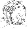
- the supporting contour (5) has at least one or a plurality of radially extending arms, wherein in an advantageous embodiment, the Supporting contour (5) has four arms (6, 7, 8, 9), of which in the installed state two diagonally run. In the end, all four arms (6, 7, 8, 9) branches (10) whose Ends are each interconnected by radially outwardly curved struts (11).
- the two upper arms (6, 9) and the two lower arms (7, 8) are also each connected by straight struts (12). Between the two left arms (6, 7) and the two right arms (8, 9) are arranged inwardly curved struts (13). On this way is by the struts (11, 12, 13) of the closed circumference of the supporting contour (5) formed, which by two in each case diagonally extending pairs of arms (6, 8 and 7, 9) cut and carries the bearing seat (4) in the center.
- the struts 11 and 12 and the top two Arms (6, 9) are provided with bearing lugs (14) or centering lugs (15) whose function explained later.
- the entire supporting contour (5) is as a one-piece molding of cast iron produced. In the area of the bore (16), which forms the bearing seat (4), takes place after casting a machining operation to precisely define the fit for the bearings.
- the above-described supporting contour (4) is inserted into an injection mold (not shown).
- the bore (16) on a mandrel (not shown) inserted the Centering lugs (15) are used for precise angle fixation and prevent the bearing lugs (14) a tilting of the contour (5) in the mold.
- the mold is almost completely with a glass fiber reinforced plastic, only the bearing and centering approaches and the Bore (16) remain free.
- a one-piece tub is made, which the Mantle (2) and as the first end face of the bottom (17) of the tub (1), wherein the Contour (5) completely except for the aforementioned exceptions in the material of the soil (17) is embedded.
- FIG. 3 shows in a section the embedding of the contour (5).
- the inner surface of the bottom (17) except for a bulge (18) in the area of Bearing seat (4) is flat.
- the tub is characterized by a front cap (19) shown in Figure 4, which then the second end face forms, completed to a tub (1).
- a front cap (19) shown in Figure 4 for mutual attachment of the both parts are screw domes (20) provided. It has proved to be advantageous for provide each attachment point dome (20) with two threaded holes (21, 22). hereby is also after damage to the thread (21) in a dome (20) - about after repeated Loosening the screws - a secure and tight connection of tub and front cap by using the second thread (22) possible.
- the balance weight Similar to the supporting contour are molded around and so on the material of the Front cap to be embedded. This eliminates the separate attachment.
- the storage for the drum exists of a front and a rear radial ball bearing (26, 27) by press fitting in the receiving bore (16) of the bearing housing (4) are fixed and the shaft journal (30) take up.
- the front bearing (26) is protected by a radial shaft seal (28), the in the front of the bearing housing (4) located opening (16 a) of the tub base (17) is used.
- the bearing housing (4) contains two continuous drainage holes (33, 34), of which the one (33) in the region of the radial shaft sealing ring (28) and the another (34) between the two bearings (27, 28) in the receiving bore (16) opens.
- the bearing housing (4) For the preparation of the tub, first the bearing housing (4) with the two Drain holes (33, 34) provided. Subsequently, the contour (5) as a unit, from Bearing cross and bearing housing in the cavity of an injection mold (not shown) inserted, which determines the outer contour of a tub.
- This tub consists of the Jacket (2) and the bottom (17) of the tub (1).
- two cores (not shown) are driven, whose Protruding ends of the opposite end of the radial shaft seal (28).
- the Inner wall of the bore (33, 34) are also coated with plastic (37).
- the core has a smaller diameter than the bore (33, 34), the thickness of the Plastic coating of half the difference between the diameter of the bore (33, 34) is determined or determined in the bearing housing and the diameter of the core.
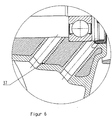
- FIG. 7 a further advantageous embodiment of the bore (33, 34) shown, in which the inner wall only in a partial area with plastic (37 a) is coated.
- the core is introduced only in the first area of the bore (33, 34) and seals at the offset (38) to the rear of the bore.
- the core a smaller diameter than the bore (33, 34) in the first region, wherein the Thickness of the plastic coating from the half difference between the first diameter of the Bore (33, 34) results in the bearing housing and the diameter of the core.
Landscapes
- Engineering & Computer Science (AREA)
- Textile Engineering (AREA)
- General Engineering & Computer Science (AREA)
- Mechanical Engineering (AREA)
- Manufacturing & Machinery (AREA)
- Main Body Construction Of Washing Machines And Laundry Dryers (AREA)
- Processing And Handling Of Plastics And Other Materials For Molding In General (AREA)
- Injection Moulding Of Plastics Or The Like (AREA)
- Moulds For Moulding Plastics Or The Like (AREA)
Abstract
Description
Die Erfindung betrifft ein Waschaggregat für eine Waschmaschine mit einem im wesentlichen
hohlzylinderförmigen Laugenbehälter aus einem insbesondere glasfaserverstärkten Kunststoff,
bestehend aus zwei Stirnflächen und einem Mantel, mit einer im Laugenbehälter angeordneten,
um eine horizontale oder schräge Achse drehbaren, ebenfalls hohlzylindrischen Trommel, und
mit einem Lagersitz zur fliegenden Lagerung der Trommel durch Aufnahme eines mit ihr
verbundenen Wellenzapfens. Außerdem betrifft die Erfindung ein Verfahren zur Herstellung
eines Waschaggregats für eine Waschmaschine mit einem im wesentlichen hohlzylinderförmigen
Laugenbehälter, bestehend aus zwei Stirnflächen und einem Mantel, mit einer im
Laugenbehälter angeordneten, um eine horizontale oder schräge Achse drehbaren, ebenfalls
hohlzylindrischen Trommel, und mit einem im Bereich einer Stirnfläche angeordneten Tragkontur,
in dessen Zentrum ein Lagersitz zur fliegenden Lagerung der Trommel durch Aufnahme
eines mit ihr verbundenen Wellenzapfens angeordnet ist
Waschmaschinen mit einem Waschaggregat, bei dem der Laugenbehälter aus Edelstahl-Blech
hergestellt ist, sind beispielsweise aus der DE-OS 27 19 336 bekannt. Edelstahl-Laugenbehälter
kommen auch bei den von der Anmelderin hergestellten und vertriebenen Waschmaschinen
zum Einsatz. Zur fliegenden Lagerung der Trommel besitzen diese einen Wellenzapfen,
welcher von zwei voneinander beabstandeten Lagern aufgenommen wird. Diese beiden
Lager sind in einem hülsenförmigen Lagersitz angeordnet. Bei den vorgenannten Waschmaschinen
dient zur Halterung und Befestigung des Lagersitzes am Laugenbehälter ein Tragkreuz
aus Gusseisen. Trag- oder Lagerkreuz inklusive Lagersitz und Laugenbehälter werden als
getrennte Bauteile hergestellt und nachträglich durch Schrauben oder Klemmringe verbunden.The invention relates to a washing unit for a washing machine with a substantially hollow cylindrical tub made of a particular glass fiber reinforced plastic, consisting of two end faces and a jacket, arranged with a tub in the tub, about a horizontal or oblique axis rotatable, also hollow cylindrical drum, and with a bearing seat for flying support of the drum by receiving a connected thereto shaft journal. In addition, the invention relates to a method for producing a washing unit for a washing machine with a substantially hollow cylindrical tub, consisting of two end faces and a jacket, arranged with a tub in the tub, about a horizontal or oblique axis rotatable, also hollow cylindrical drum, and with a in the Area of an end face arranged supporting contour, in the center of which a bearing seat for flying mounting of the drum is arranged by receiving a shaft journal connected to it
Washing machines with a washing unit, in which the tub is made of stainless steel sheet, are known for example from DE-OS 27 19 336. Stainless steel tubs are also used in the washing machines manufactured and sold by the applicant. For flying storage of the drum, these have a shaft journal which is received by two spaced-apart bearings. These two bearings are arranged in a sleeve-shaped bearing seat. In the aforementioned washing machines used for holding and fixing the bearing seat on the tub a spider made of cast iron. Support or bearing cross including bearing seat and tub are made as separate components and subsequently connected by screws or clamping rings.
Seit einiger Zeit wird bei der Herstellung von Laugenbehältern Kunststoff - meist glasfaserverstärkt - anstelle von Blech verwendet. Waschmaschinen mit Kunststoff-Laugenbehältern sind beispielsweise aus der EP 0 043 429 A1, der EP 0 374 519 A2 und der DE 298 21 140 A1 bekannt. Bei den bekannten Waschmaschinen ist es üblich, ein zylindrisches Lagergehäuse aus Metall (i. d. R. eine spanend bearbeitete Gusseisenkonstruktion) als Lagersitz zu verwenden und dieses bei der Herstellung des Laugenbehälter-Bodens mit Kunststoff zu umspritzen. Daneben ist es aus der DE 100 40 319 C1 bekannt, auf einen Lagersitz aus Metall zu verzichten und die Lager mit Kunststoff zu umspritzen. Varianten, bei denen wie beim Edelstahl-Laugenbehälter ein Tragkreuz separat gefertigt und am Laugenbehälter befestigt wird, sind nicht bekannt und nicht zweckmäßig, da die Koppelstellen aus nachstehend erläuterten Gründen sehr hoch belastet werden, was zu einem Reißen des Kunststoffs führen kann. For some time, the production of liquor containers plastic - usually glass fiber reinforced - used instead of sheet metal. Washing machines with plastic tubs are for example from EP 0 043 429 A1, EP 0 374 519 A2 and DE 298 21 140 A1 known. In the known washing machines, it is customary, a cylindrical bearing housing made of metal (usually a machined cast iron construction) as a bearing seat Use this in the manufacture of the tub base with plastic too overmolded. In addition, it is known from DE 100 40 319 C1, on a bearing seat made of metal to dispense and to encase the bearings with plastic. Variants in which like the Stainless steel tub A spider is made separately and attached to the tub are not known and not appropriate, since the coupling points from below explained reasons are charged very high, resulting in cracking of the plastic can.
Die deutsche Offenlegungsschrift DE 199 60 501 A1 offenbart einen Laugenbehälter aus Kunststoff, der ein zylindrisches Lagergehäuse enthält. Dieses Lagergehäuse enthält einen zusätzlichen rotationssymmetrischen Kragen, der zur Aufnahme und Befestigung eines Stators für einen Direktantrieb dient. Die Umspritzung des Kunststoffs erstreckt sich hierbei jedoch nur bis zur äußeren Kante, bzw. des äußeren Endes des Kragens. Da dieses Lagergehäuse mit integriertem Statortragteil nur einen geringen Durchmesser aufweist, überträgt es sehr große Kräfte auf die Rückwand des Laugenbehälters, was mit hohem konstruktiven Aufwand, wie Verstärkungsrippen kompensiert werden muss. Auch die Wärmeableitung des Lagers ist nicht vorteilhaft gewährleistet, so dass es zu Temperaturspitzen bzw. starken Temperaturunterschieden innerhalb der Rückwand des Laugenbehälters kommen kann.The German patent application DE 199 60 501 A1 discloses a tub Plastic containing a cylindrical bearing housing. This bearing housing contains a additional rotationally symmetrical collar, which is used to hold and fasten a stator for a direct drive. The encapsulation of the plastic extends here only to the outer edge, or the outer end of the collar. As this bearing housing with integrated stator support has only a small diameter, it transmits very large Forces on the back wall of the tub, resulting in high design effort, such as Reinforcing ribs must be compensated. The heat dissipation of the bearing is not ensures advantageous, so that there are temperature peaks or strong temperature differences can come within the back wall of the tub.
Bei den heute üblichen hohen Schleuderdrehzahlen von bis zu 1800 min-1 kommt es im Bereich der Lager durch Reibung zu einer Erhitzung auf Temperaturen um 100 °C. Die so erzeugte Wärmeenergie wird bei den bekannten Waschaggregaten mit Kunststoff-Laugenbehälter entweder über das Lagergehäuse oder direkt an den Laugenbehälter-Boden abgegeben. Dadurch kann es zu Materialschäden und zu einem Lockern der Verbindung zwischen Metall und Kunststoff kommen. Außerdem führen die hohen Drehzahlen bei Unwuchten, welche durch unsymmetrische Wäscheverteilung in der Trommel erzeugt werden, zu hohen Biegekräften, die über die Lager in den Laugenbehälter-Boden eingeleitet werden. Auch dies kann den Boden selbst oder seine Verbindung mit dem Lagergehäuse und mit dem Laugenbehältermantel schädigen.At today's usual high spin speeds of up to 1800 min-1 it comes in Frictional area of the bearings to a temperature of around 100 ° C. The way generated heat energy is in the known washing units with plastic tub either via the bearing housing or directly to the tub base issued. This can lead to material damage and to a loosening of the connection come between metal and plastic. In addition, the high speeds contribute Imbalances, which are generated by asymmetrical laundry distribution in the drum, too high bending forces, which are introduced via the bearings in the tub bottom. This too can be the floor itself or its connection with the bearing housing and with the Damage the tub casing.
Die deutsche Offenlegungsschrift DE 102 16 517 A1 offenbart ein Verfahren zur Herstellung eines Laugenbottichs aus Kunststoff. Hierbei werden mechanische Funktionsteile in die Spritzgussform eingelegt und durch Umspritzen am Laugenbottich angebracht. Zum genauen und zuverlässigen Positionierung von mechanischen Funktionsteilen sind jedoch weitere Maßnahmen notwendig.German Offenlegungsschrift DE 102 16 517 A1 discloses a method for the production a liquor vat made of plastic. Here are mechanical functional parts in the injection mold inserted and attached by overmolding on Laugenbottich. To the exact and However, reliable positioning of mechanical functional parts are further measures necessary.
Der Erfindung stellt sich somit das Problem, ein Waschaggregat für eine Waschmaschine mit einem Laugenbehälter aus Kunststoff zu offenbaren, bei welchem eine sichere Ableitung von Kräften und hohen Temperaturen aus dem Lagerbereich gewährleistet ist. Der Erfindung stellt sich auch das Problem, ein einfaches und rationelles Verfahren zur Herstellung eines solchen Waschaggregats zu offenbaren.The invention thus raises the problem of having a washing unit for a washing machine To reveal a plastic tub, in which a safe derivation of Forces and high temperatures from the storage area is guaranteed. The invention provides also the problem, a simple and efficient method for producing such To reveal washing aggregate.
Erfindungsgemäß wird dieses Problem durch ein Waschaggregat bzw. durch ein Verfahren mit
den Merkmalen der unabhängigen Patentansprüche 1 und 9 gelöst. Vorteilhafte Ausgestaltungen
und Weiterbildungen der Erfindung ergeben sich aus den jeweils nachfolgenden Unteransprüchen. According to the invention, this problem is solved by a washing unit or by a method
the features of the
Die mit der Erfindung erreichbaren Vorteile bestehen neben einer guten Wärme- und Kraftableitung aus dem Bereich der Lager in einer Erhöhung der Festigkeit des Laugenbehälter-Bodens. Hierdurch kann auf die bei Serien-Waschmaschinen mit Kunststoff-Laugenbehältern üblichen Versteifungsstreben verzichtet werden, was zu einer Materialeinsparung führt. Außerdem kann die aus der EP 0 043 429 A1 bekannte, bei Serien-Waschmaschinen ebenfalls übliche Versteifung des Bodens durch unterschiedlich tiefe Sektoren entfallen und in einer vorteilhaften Ausführungsform die zum Laugenbehälterinneren gerichtete Seite der Stirnfläche annähernd eben ausgebildet werden. Hierdurch werden Geräusche vermieden, die bei der Bewegung der Waschflotte in den durch die tieferen Sektoren gebildeten Taschen entstehen.The achievable with the invention advantages are in addition to a good heat and power dissipation from the field of bearings in an increase in the strength of the tub base. This can be applied to the standard washing machines with plastic tubs conventional stiffening struts are omitted, resulting in a material saving. In addition, the known from EP 0 043 429 A1, in series washing machines also usual stiffening of the soil by differently deep sectors accounts for and in one advantageous embodiment, the side facing the tub interior side of the end face be formed approximately flat. As a result, noises are avoided in the Movement of the wash liquor arise in the pockets formed by the deeper sectors.
In einer zweckmäßigen Ausführungsform besitzt die Tragkontur im Einbauzustand zumindest einen oder mehrere radial verlaufende Arme, bezogen auf die Fläche des Laugenbehälter-Bodens.In an expedient embodiment, the supporting contour has at least in the installed state one or more radially extending arms, based on the surface of the tub base.
In einer weiteren zweckmäßigen Ausführungsform verlaufen die Arme der Tragkontur im Einbauzustand jeweils diagonal.In a further expedient embodiment, the arms of the support contour run in the Installation state each diagonal.
Es ist außerdem vorteilhaft, zwischen jeweils zwei benachbarten Armen der Tragkontur an ihren Enden zwei erste Verbindungsstreben aus Metall, vorzugsweise aus Gusseisen anzuordnen.It is also advantageous between each two adjacent arms of the supporting contour at their Ends two first connecting struts of metal, preferably to arrange cast iron.
Hierdurch wird die Stabilität des Laugenbehälter-Bodens weiter erhöht und die Möglichkeit der Temperaturableitung weiter verbessert. Außerdem erfolgt hierdurch eine optimale Verteilung von Masse zur dynamischen Kompensation von Unwuchtkräften. Es ist zweckmäßig, die ersten Verbindungsstreben jeweils zwischen den Enden der beiden oberen Arme der Tragkontur und zwischen den Enden der beiden unteren Arme der Tragkontur verlaufen zu lassen.As a result, the stability of the tub bottom is further increased and the possibility of Temperature derivative further improved. In addition, this results in an optimal distribution from mass to dynamic compensation of unbalance forces. It is appropriate, the first Connecting struts respectively between the ends of the two upper arms of the supporting contour and run between the ends of the two lower arms of the supporting contour.
Eine weitere Erhöhung der Steifigkeit des Bodens erfolgt dadurch, dass die Arme der Tragkontur im Endbereich Verzweigungen aufweisen, was noch dadurch verbessert wird, dass zwischen den Enden der Verzweigungen zweite Verbindungstreben aus Metall, vorzugsweise aus Gusseisen angeordnet sind.A further increase in the rigidity of the soil takes place in that the arms of the supporting contour have branches in the end area, which is further improved by that between the ends of the branches second connecting struts of metal, preferably made of cast iron.
In einer weiteren vorteilhaften Ausführungsform sind zwischen den beiden linken Armen und zwischen den beiden rechten Armen der Tragkontur jeweils in deren Mittelbereich dritte Verbindungsstreben aus Metall, vorzugsweise aus Gusseisen angeordnet. Durch die einwärts gerichtete Anordnung dieser Verbindungsstreben können mehrere ineinandergeschachtelte Tragkonturen mit einem einzigen Anguss gefertigt werden.In a further advantageous embodiment are between the two left arms and between the two right arms of the supporting contour in each case in the central region third Connecting struts of metal, preferably arranged from cast iron. Through the inward Directional arrangement of these connecting struts can be several nested Tragkonturen be manufactured with a single sprue.
Durch das erfindungsgemäße Verfahren zur Herstellung eines Waschaggregats ergibt sich der Vorteil, dass Tragkontur und Laugenbehälter-Boden ohne die Verwendung von Befestigungselementen eine innige Verbindung eingehen, wodurch insgesamt ein preiswerter und trotzdem stabiler Aufbau erreicht wird. The inventive method for producing a washing aggregate results in the Advantage of supporting contour and tub floor without the use of fasteners make an intimate connection, making a total of a cheaper and still stable construction is achieved.
Bei zweckmäßigen Ausführungsformen des Verfahrens kann vor dem Einlegen der Tragkontur in die Spritzgussform eine spanende Bearbeitung des Lagersitzes erfolgen und die das Tragkreuz enthaltende Stirnfläche (der Laugenbehälter-Boden) und der Mantel des Laugenbehälters einstückig hergestellt werden. Das so hergestellte Bauteil kann auf einfache Weise durch die fehlende Stirnfläche komplettiert werden, wobei zu deren Herstellung mindestens ein Ausgleichsgewicht mit einem insbesondere glasfaserverstärkten Kunststoff derart umspritzt werden kann, dass das(die) Ausgleichsgewicht(e) wenigstens annähernd vollständig in das Material der Stirnfläche eingebettet ist(sind). Alternativ ist eine Verwendung von zwei separaten Bauteilen - Boden und Ausgleichsgewichte - möglich.In expedient embodiments of the method can before inserting the supporting contour in the injection mold, a machining of the bearing seat done and the the bearing cross containing end face (the tub base) and the jacket of the tub be made in one piece. The component thus produced can easily by the Missing end face are completed, wherein at least one for their production Balancing weight with a particular glass fiber reinforced plastic so encapsulated can be that the (the) balancing weight (s) at least approximately completely in the Material of the face is embedded (are). Alternatively, use is two separate Components - floor and balance weights - possible.
In einer weiteren vorteilhaften Ausführungsform des Verfahrens wird zur Herstellung einer Abflussbohrung im Bereich der Dichtungsanordnung für den Wellenzapfen der Trommel ein Kern in die genannte Abflussbohrung eingefügt, wobei ein Ende des Kernes aus dem der Dichtungsanordnung gegenüberliegenden Ende der Abflussbohrung herausragt. Nach dem Umspritzen des Lagergehäuses mit Kunststoff wird der Kern entfernt, wodurch eine durchgängige Abflussbohrung bereitgestellt wird. Es ist hierbei zweckmäßig, eine weitere Abflussbohrung im Bereich zwischen den Radial-Wälzlagern anzuordnen.In a further advantageous embodiment of the method is for producing a Drain hole in the region of the seal assembly for the shaft journal of the drum Core inserted in said drainage hole, with one end of the core of the Sealing arrangement protrudes opposite end of the drain hole. After this Encasing the bearing housing with plastic, the core is removed, creating a continuous Drainage hole is provided. It is expedient here, another drain hole to be arranged in the area between the radial roller bearings.
In einer weiteren Ausführungsform des Verfahrens hat der eingeführte Kern einen geringeren Durchmesser als die Abflussbohrung im Lagergehäuse, so dass zwischen Kern und Innenwandung der Bohrung ein Kunststoffüberzug hergestellt wird. In einer weiteren Ausführungsform hat die Abflussbohrung im Lagergehäuse in einem äußeren Bereich einen größeren Durchmesser und in einem inneren Bereich einen kleineren Durchmesser. Der in die Bohrung eingeführte Kern ist hierbei so bemessen, dass beim Umspritzen der Kunststoff nur in den äußeren Bereich zwischen Kern und innerer Wandung der Abflussbohrung im Lagergehäuse gelangt, wobei der innere Bereich nicht mit Kunststoff überzogen wird.In a further embodiment of the method, the introduced core has a smaller one Diameter as the drain hole in the bearing housing, allowing between core and inner wall the bore is made of a plastic coating. In a further embodiment has the drain hole in the bearing housing in an outer area a larger Diameter and in an inner area a smaller diameter. The in the hole introduced core is in this case so dimensioned that when encapsulating the plastic only in the outer area between the core and the inner wall of the drain hole in the bearing housing passes, wherein the inner area is not covered with plastic.
Ein Ausführungsbeispiel der Erfindung ist in den Zeichnungen rein schematisch dargestellt und wird nachfolgend näher beschrieben. Es zeigen
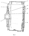
Figur 1- die perspektivische Rückansicht eines Laugenbehälters (1) mit integrierter Tragkontur;
Figur 2- die Tragkontur als Einzelheit;
Figur 3- einen Schnitt durch die Seitenansicht des Laugenbehälters (1);
Figur 4- die perspektivische Vorderansicht des Laugenbehälters (1);
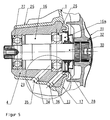
Figur 5- die Lageranordnung eines Waschaggregats für eine Waschmaschine in der Seitenansicht im Schnitt und
Figur 6 + 7- eine Detailansicht der Abflussbohrungen in der Seitenansicht im Schnitt.
- FIG. 1
- the perspective rear view of a tub (1) with integrated support contour;
- FIG. 2
- the supporting contour as a detail;
- FIG. 3
- a section through the side view of the tub (1);
- FIG. 4
- the front perspective view of the tub (1);
- FIG. 5
- the bearing assembly of a washing unit for a washing machine in the side view in section and
- Figure 6 + 7
- a detailed view of the drain holes in the side view in section.
Der in Figur 1 dargestellte Laugenbehälter (1) kommt in dem Waschaggregat einer mantelbeschickbaren Waschmaschine, einem sogenannten Toplader zum Einsatz. Aus diesem Grund ist der Laugenbehältermantel (2) mit einer Öffnung (3) versehen, welche mit der Öffnung im Mantel einer in den Zeichnungen nicht dargestellten Trommel korrespondiert. Bei Verwendung des Laugenbehälters im Waschaggregat einer frontbeschickbaren Waschmaschine, einem sogenannten Frontlader, ist die Öffnung in der vorderen Deckfläche angeordnet (beim Toplader geschlossen, s. Figur 4).The tub (1) shown in Figure 1 comes in the washing unit a mantelbeschickbaren Washing machine, a so-called Toplader used. For this reason the lye container casing (2) is provided with an opening (3) which communicates with the opening in the Jacket corresponds to a drum, not shown in the drawings. Using of the tub in the washing unit of a front-loading washing machine, a so-called front loader, the opening in the front deck area is arranged (the top loader closed, s. FIG. 4).
Zur fliegenden Lagerung besitzt die Trommel in bekannter Weise einen Wellenzapfen, welcher
von zwei voneinander beabstandeten Lagern aufgenommen wird (nicht dargestellt). Diese
beiden Lager sind in einem hülsenförmigen Lagersitz (4) angeordnet, welcher sich im Zentrum
einer in Figur 2 dargestellten Tragkontur (5) befindet. Die Tragkontur (5) besitzt zumindest einen
oder mehrere radial verlaufende Arme, wobei in einer vorteilhaften Ausführungsform die
Tragkontur (5) vier Arme (6, 7, 8, 9) besitzt, von denen im Einbauzustand jeweils zwei diagonal
verlaufen. Im Endbereich weisen alle vier Arme (6, 7, 8, 9) Verzweigungen (10) auf, deren
Enden jeweils durch radial nach außen gekrümmte Streben (11) miteinander verbunden sind.
Darüber hinaus sind auch die beiden oberen Arme (6, 9) und die beiden unteren Arme (7, 8)
jeweils durch gerade Streben (12) verbunden. Zwischen den beiden linken Armen (6, 7) und
den beiden rechten Armen (8, 9) sind nach innen gekrümmte Streben (13) angeordnet. Auf
diese Weise wird durch die Streben (11, 12, 13) der geschlossene Umfang der Tragkontur (5)
gebildet, welcher durch zwei jeweils diagonal verlaufende Armpaare (6, 8 bzw. 7, 9) geschnitten
wird und im Zentrum den Lagersitz (4) trägt. Die Streben 11 und 12 und die beiden oberen
Arme (6, 9) sind mit Lageransätzen (14) oder Zentrieransätzen (15) versehen deren Funktion
später erklärt ist. Die gesamte Tragkontur (5) wird als einstückiges Formteil aus Gusseisen
hergestellt. Im Bereich der Bohrung (16), die den Lagersitz (4) bildet, erfolgt nach dem Gießen
eine spanende Bearbeitung, um die Passung für die Lager genau zu definieren.For flying storage, the drum has in a known manner a shaft journal, which
is received by two spaced apart bearings (not shown). These
two bearings are arranged in a sleeve-shaped bearing seat (4), which is in the center
a support contour (5) shown in Figure 2 is located. The supporting contour (5) has at least one
or a plurality of radially extending arms, wherein in an advantageous embodiment, the
Supporting contour (5) has four arms (6, 7, 8, 9), of which in the installed state two diagonally
run. In the end, all four arms (6, 7, 8, 9) branches (10) whose
Ends are each interconnected by radially outwardly curved struts (11).
In addition, the two upper arms (6, 9) and the two lower arms (7, 8) are also
each connected by straight struts (12). Between the two left arms (6, 7) and
the two right arms (8, 9) are arranged inwardly curved struts (13). On
this way is by the struts (11, 12, 13) of the closed circumference of the supporting contour (5)
formed, which by two in each case diagonally extending pairs of arms (6, 8 and 7, 9) cut
and carries the bearing seat (4) in the center. The
Die vorbeschriebene Tragkontur (4) wird in eine Spritzgussform (nicht dargestellt) eingelegt. Zur lagegenauen Fixierung wird die Bohrung (16) auf einen Dorn (nicht dargestellt) gesteckt, die Zentrieransätze (15) dienen zur winkelgenauen Fixierung und die Lageransätze (14) verhindern ein Kippen der Kontur (5) in der Form. Anschließend wird die Form nahezu vollständig mit einem glasfaserverstärkten Kunststoff umspritzt, nur die Lager- und Zentrieransätze und die Bohrung (16) bleiben frei. Auf diese Weise wird ein einstückiger Bottich hergestellt, welcher den Mantel (2) und als erste Stirnfläche den Boden (17) des Laugenbehälters (1) bildet, wobei die Kontur (5) vollständig bis auf die vorgenannten Ausnahmen in das Material des Bodens (17) eingebettet ist. Figur 3 zeigt in einem Schnitt die Einbettung der Kontur (5). Hier ist außerdem zu sehen, dass die Innenfläche des Bodens (17) bis auf eine Auswölbung (18) im Bereich des Lagersitzes (4) eben ist. The above-described supporting contour (4) is inserted into an injection mold (not shown). to Precise fixation, the bore (16) on a mandrel (not shown) inserted, the Centering lugs (15) are used for precise angle fixation and prevent the bearing lugs (14) a tilting of the contour (5) in the mold. Subsequently, the mold is almost completely with a glass fiber reinforced plastic, only the bearing and centering approaches and the Bore (16) remain free. In this way, a one-piece tub is made, which the Mantle (2) and as the first end face of the bottom (17) of the tub (1), wherein the Contour (5) completely except for the aforementioned exceptions in the material of the soil (17) is embedded. FIG. 3 shows in a section the embedding of the contour (5). Here is as well to see that the inner surface of the bottom (17) except for a bulge (18) in the area of Bearing seat (4) is flat.
Der Bottich wird durch eine in Figur 4 dargestellte Frontkappe (19), die dann die zweite Stimfläche bildet, zu einem Laugenbehälter (1) komplettiert. Zur gegenseitigen Befestigung der beiden Teile sind Schraubdome (20) vorgesehen. Dabei hat es sich als vorteilhaft erwiesen, für jede Befestigungsstelle Dome (20) mit zwei Gewindebohrungen (21, 22) vorzusehen. Hierdurch ist auch nach einer Beschädigung des Gewindes (21) in einem Dom (20) - etwa nach mehrmaligem Lösen der Schrauben - eine sichere und dichte Verbindung von Bottich und Frontkappe durch Verwendung des zweiten Gewindes (22) möglich.The tub is characterized by a front cap (19) shown in Figure 4, which then the second end face forms, completed to a tub (1). For mutual attachment of the both parts are screw domes (20) provided. It has proved to be advantageous for provide each attachment point dome (20) with two threaded holes (21, 22). hereby is also after damage to the thread (21) in a dome (20) - about after repeated Loosening the screws - a secure and tight connection of tub and front cap by using the second thread (22) possible.
An der Frontkappe (19) ist ein hufeisenförmiges Ausgleichsgewicht (23), vorteilhafterweise auch aus Gusseisen hergestellt, über weitere Schraubdome (24) befestigt. In einer in den Zeichnungen nicht dargestellten Ausführungsform kann anstatt des geteilten Aufbaus das Ausgleichsgewicht ähnlich wie die Tragkontur umspritzt werden und so von dem Material der Frontkappe eingebettet werden. Hierdurch entfällt die separate Befestigung.At the front cap (19) is a horseshoe-shaped balance weight (23), advantageously also Made of cast iron, attached via additional screw domes (24). In one in the drawings not shown embodiment, instead of the divided structure, the balance weight Similar to the supporting contour are molded around and so on the material of the Front cap to be embedded. This eliminates the separate attachment.
Ein weiteres Ausführungsbeispiel der Erfindung ist in der Figur 5 rein schematisch dargestellt und wird nachfolgend näher beschrieben. Die Figur 5 zeigt die Lageranordnung eines Waschaggregats für eine Waschmaschine in der Seitenansicht im Schnitt. Das Waschaggregat besitzt einen im Wesentlichen zylindrischen Laugenbehälter (1) und eine darin drehbar gelagerte, ebenfalls zylindrische Trommel (31) zur Aufnahme der Wäsche (nicht dargestellt). Der Laugenbehälter (1) ist aus laugenbeständigem Kunststoff hergestellt und besitzt im Zentrum seines Bodens (17) eine Öffnung (16), hinter der ein Lagergehäuse (4) angeordnet ist. Letzteres wird von einem nicht dargestellten Lagerkreuz getragen. Die Verbindung von Lagerkreuz und Lagergehäuse (4) mit dem Laugenbehälter (1) ist ein Teil des an späterer Stelle beschriebenen Herstellungsverfahrens. Ein mit der Trommel (31) über einen Flansch (32) verbundener Wellenzapfen (30) ist durch die Öffnung (16) hindurch geführt. Die Lagerung für die Trommel besteht aus einem vorderen und einem hinteren Radialkugellager (26, 27), die durch Presspassung in der Aufnahmebohrung (16) des Lagergehäuses (4) fixiert sind und den Wellenzapfen (30) aufnehmen. Das vordere Lager (26) wird durch einen Radialwellendichtring (28) geschützt, der in die vor dem Lagergehäuse (4) befindliche Öffnung (16a) des Laugenbehälterbodens (17) eingesetzt ist. Im Lagergehäuse (4) befinden sich zwei durchgängige Abflussbohrungen (33, 34), von denen die eine (33) im Bereich des Radialwellendichtrings (28) und die andere (34) zwischen den beiden Lagern (27, 28) in die Aufnahmebohrung (16) mündet.A further embodiment of the invention is shown purely schematically in FIG and will be described in more detail below. FIG. 5 shows the bearing arrangement of a washing aggregate for a washing machine in the side view in section. The washing unit has a substantially cylindrical tub (1) and a rotatably mounted therein, also cylindrical drum (31) for receiving the laundry (not shown). The tub (1) is made of alkali-resistant plastic and is in the center of his Floor (17) has an opening (16), behind which a bearing housing (4) is arranged. The latter will carried by a bearing cross, not shown. The connection of bearing cross and bearing housing (4) with the tub (1) is a part of the manufacturing process described later. A shaft journal connected to the drum (31) via a flange (32) (30) is passed through the opening (16). The storage for the drum exists of a front and a rear radial ball bearing (26, 27) by press fitting in the receiving bore (16) of the bearing housing (4) are fixed and the shaft journal (30) take up. The front bearing (26) is protected by a radial shaft seal (28), the in the front of the bearing housing (4) located opening (16 a) of the tub base (17) is used. The bearing housing (4) contains two continuous drainage holes (33, 34), of which the one (33) in the region of the radial shaft sealing ring (28) and the another (34) between the two bearings (27, 28) in the receiving bore (16) opens.
Zur Herstellung des Laugenbehälters wird zunächst das Lagergehäuse (4) mit den beiden Abflussbohrungen (33, 34) versehen. Anschließend wird die Kontur (5) als Einheit, aus Lagerkreuz und Lagergehäuse in die Kavität eines Spritzgießwerkzeugs (nicht dargestellt) eingelegt, welche die Außenkontur eines Bottichs bestimmt. Dieser Bottich besteht aus dem Mantel (2) und dem Boden (17) des Laugenbehälters (1). Zur lagegenauen Fixierung wird die Aufnahmebohrung (16) auf einen Dorn (nicht dargestellt) gesteckt. In die beiden Abflussbohrungen (33, 34) im Lagergehäuse (4) werden zwei Kerne (nicht dargestellt) gefahren, deren Enden aus dem dem Radialwellendichtring (28) gegenüberliegenden Ende herausragen. Anschließend werden Lagergehäuse (4), Kerne und Lagerkreuz mit einer polymeren Masse aus glasfaserverstärkten Kunststoff umspritzt, nur die Aufnahmebohrung (16) bleibt frei. Auf diese Weise wird der Bottich einstückig hergestellt. Nachdem die eingespritzte polymere Masse (Schmelze) erstarrt ist, wird der vordere und der hintere Kern mit einem Schieber aus der jeweiligen Abflussbohrung (33, 34) herausgezogen und es entstehen in dem das Lagergehäuse (4) umgebenden Kunststoffmantel (25) zwei freie Durchflüsse (35, 36). Hierüber kann angesammeltes Kondenswasser aus der Bohrung (16) in den Außenbereich (29) des Lagergehäuses (4) abgeleitet werden.For the preparation of the tub, first the bearing housing (4) with the two Drain holes (33, 34) provided. Subsequently, the contour (5) as a unit, from Bearing cross and bearing housing in the cavity of an injection mold (not shown) inserted, which determines the outer contour of a tub. This tub consists of the Jacket (2) and the bottom (17) of the tub (1). For positionally accurate fixation is the Receiving hole (16) on a mandrel (not shown) inserted. In the two drainage holes (33, 34) in the bearing housing (4) two cores (not shown) are driven, whose Protruding ends of the opposite end of the radial shaft seal (28). Subsequently Bearing housing (4), cores and bearing cross with a polymeric mass glass-fiber reinforced plastic, only the receiving bore (16) remains free. To this Way, the tub is made in one piece. After the injected polymeric mass (Melt) is solidified, the front and the rear core with a slide out of the respective outflow bore (33, 34) pulled out and there arise in which the bearing housing (4) surrounding plastic jacket (25) has two free flows (35, 36). About this can Accumulated condensed water from the bore (16) in the outer region (29) of the bearing housing (4) are derived.
Zur weiteren vorteilhaften Ausgestaltung der Bohrung kann, wie in der Figur 6 dargestellt, die Innenwandung der Bohrung (33, 34) ebenfalls mit Kunststoff (37) überzogen werden. Hierbei hat der Kern einen geringeren Durchmesser, als die Bohrung (33, 34), wobei die Dicke des Kunststoffüberzugs aus der halben Differenz zwischen dem Durchmesser der Bohrung (33, 34) im Lagergehäuse und dem Durchmesser des Kerns bestimmt bzw. festgelegt wird. In Figur 7 ist eine weitere vorteilhafte Ausgestaltung der Bohrung (33, 34) dargestellt, in der die Innenwandung nur in einem Teilbereich mit Kunststoff (37 a) überzogen ist. Hierbei hat die Bohrung (33, 34) im Lagergehäuse in einem vorderen Bereich einen ersten Durchmesser und in einem hinteren Bereich einen zweiten Durchmesser, wobei der erste Durchmesser größer ist, als der zweite Durchmesser. Der Kern wird nur in den ersten Bereich der Bohrung (33, 34) eingeführt und dichtet an dem Versatz (38) zum hinteren Bereich der Bohrung ab. Hierbei hat der Kern einen geringeren Durchmesser, als die Bohrung (33, 34) im ersten Bereich, wobei sich die Dicke des Kunststoffüberzugs aus der halben Differenz zwischen dem ersten Durchmesser der Bohrung (33, 34) im Lagergehäuse und dem Durchmesser des Kerns ergibt.For a further advantageous embodiment of the bore can, as shown in the figure 6, the Inner wall of the bore (33, 34) are also coated with plastic (37). in this connection the core has a smaller diameter than the bore (33, 34), the thickness of the Plastic coating of half the difference between the diameter of the bore (33, 34) is determined or determined in the bearing housing and the diameter of the core. In FIG. 7 a further advantageous embodiment of the bore (33, 34) shown, in which the inner wall only in a partial area with plastic (37 a) is coated. Here has the hole (33, 34) in the bearing housing in a front region a first diameter and in a rear portion of a second diameter, wherein the first diameter is larger than the second diameter. The core is introduced only in the first area of the bore (33, 34) and seals at the offset (38) to the rear of the bore. Here is the core a smaller diameter than the bore (33, 34) in the first region, wherein the Thickness of the plastic coating from the half difference between the first diameter of the Bore (33, 34) results in the bearing housing and the diameter of the core.
Claims (16)
dadurch gekennzeichnet, dass die Tragkontur (5) ein einstückiges Formteil ist und zumindest einen oder mehrere radial verlaufende Arme (6, 7, 8 , 9) besitzt.Washing unit for a washing machine with a substantially hollow cylindrical tub (1) made of a particular glass fiber reinforced plastic, consisting of two end faces (17, 19) and a jacket (2) arranged with a in the tub (1), about a horizontal or oblique axis rotatable, also hollow cylindrical drum, and with a in the region of an end face (17) arranged, made of metal, preferably made of cast iron supporting contour (5) in the center of a bearing seat (4) for flying mounting of the drum by receiving a connected thereto shaft journal is arranged, wherein the supporting contour (5) is at least approximately completely embedded in the material of an end face (17),
characterized in that the supporting contour (5) is a one-piece molded part and has at least one or more radially extending arms (6, 7, 8, 9).
dadurch gekennzeichnet, dass die zum Laugenbehälterinneren gerichtete Seite der Stirnfläche (17) annähernd eben ausgebildet ist.Washing unit according to claim 1,
characterized in that the side facing the tub inner side of the end face (17) is formed approximately flat.
dadurch gekennzeichnet, dass die Tragkontur (5) ein einstückiges Formteil ist und vier diagonal verlaufende Arme (6, 7, 8, 9) besitzt.Washing unit according to claim 1,
characterized in that the supporting contour (5) is a one-piece molded part and has four diagonal arms (6, 7, 8, 9).
dadurch gekennzeichnet, dass zwischen jeweils zwei benachbarten Armen der Tragkontur (5) an ihren Enden zwei erste Verbindungsstreben (12) aus Metall, vorzugsweise aus Gusseisen angeordnet sind.Washing unit according to at least one of claims 1 or 3,
characterized in that between each two adjacent arms of the supporting contour (5) at their ends two first connecting struts (12) made of metal, preferably made of cast iron are arranged.
dadurch gekennzeichnet, dass die ersten Verbindungsstreben (12) jeweils zwischen den Enden der beiden oberen Arme (6, 9) der Tragkontur (5) und zwischen den Enden der beiden unteren Arme (7, 8) der Tragkontur (5) verlaufen.Washing unit according to claims 1 and 4
characterized in that the first connecting struts (12) each extend between the ends of the two upper arms (6, 9) of the supporting contour (5) and between the ends of the two lower arms (7, 8) of the supporting contour (5).
dadurch gekennzeichnet, dass die Arme (6, 7, 8, 9) der Tragkontur (5) im Endbereich Verzweigungen (10) aufweisen. Washing unit according to at least one of claims 1, 3 to 5,
characterized in that the arms (6, 7, 8, 9) of the supporting contour (5) in the end region branches (10).
dadurch gekennzeichnet, dass zwischen den Enden der Verzweigungen (10) zweite Verbindungsstreben (12) aus Metall, vorzugsweise aus Gusseisen angeordnet sind.Washing unit according to claim 6,
characterized in that between the ends of the branches (10) second connecting struts (12) made of metal, preferably made of cast iron are arranged.
dadurch gekennzeichnet, dass zwischen den beiden linken Armen (6, 7) und zwischen den beiden rechten Armen (8, 9) der Tragkontur (5) jeweils in deren Mittelbereich dritte Verbindungsstreben (13) aus Metall, vorzugsweise aus Gusseisen angeordnet sind.Washing unit according to at least one of claims 1, 3 to 7,
characterized in that between the two left arms (6, 7) and between the two right arms (8, 9) of the supporting contour (5) in each case in the central region third connecting struts (13) made of metal, preferably made of cast iron are arranged.
dadurch gekennzeichnet, dass vor dem Einlegen der Tragkontur (5) in die Spritzgussform eine spanende Bearbeitung des Lagersitzes (4) erfolgt.A process for producing a washing aggregate according to claim 9,
characterized in that before inserting the supporting contour (5) in the injection mold, a machining of the bearing seat (4).
dadurch gekennzeichnet, dass die die Tragkontur (5) enthaltende Stirnfläche (17) und der Mantel (3) des Laugenbehälters einstückig hergestellt werden. Process for producing a washing unit according to at least one of claims 9 or 10,
characterized in that the support contour (5) containing end face (17) and the jacket (3) of the tub are made in one piece.
dadurch gekennzeichnet, dass zur Herstellung der die Tragkontur (5) nicht enthaltenden Stirnfläche (19) mindestens ein Ausgleichsgewicht (23) mit einem insbesondere glasfaserverstärkten Kunststoff derart umspritzt wird, dass das(die) Ausgleichsgewicht(e) (23) wenigstens annähernd vollständig in das Material der Stirnfläche eingebettet ist(sind).A process for producing a washing aggregate according to at least one of claims 9 to 11,
characterized in that for the production of the support contour (5) not containing end face (19) at least one balancing weight (23) is encapsulated with a particular glass fiber reinforced plastic such that the (the) balancing weight (s) (23) at least approximately completely in the Material of the face is embedded (are).
dadurch gekennzeichnet, dass die Bohrung (33, 34) im Lagergehäuse in einem vorderen Bereich einen ersten Durchmesser und in einem hinteren Bereich einen zweiten Durchmesser aufweist, wobei der erste Durchmesser größer ist, als der zweite Durchmesser, wobei der Kern in den vorderen Bereich der Bohrung (33, 34) eingeführt wird und an einem Versatz (38) zum hinteren Bereich der Bohrung (33, 34) abdichtet.A method of manufacturing a washing aggregate according to claim 15,
characterized in that the bore (33, 34) in the bearing housing in a front region has a first diameter and in a rear region has a second diameter, wherein the first diameter is greater than the second diameter, wherein the core in the front region of the Bore (33, 34) is inserted and at an offset (38) to the rear region of the bore (33, 34) seals.
Priority Applications (3)
| Application Number | Priority Date | Filing Date | Title |
|---|---|---|---|
| PL10007272T PL2241666T3 (en) | 2003-10-29 | 2004-10-06 | Method for manufacturing a washing unit for a washing machine with a plastic tub |
| EP10007272A EP2241666B1 (en) | 2003-10-29 | 2004-10-06 | Method for manufacturing a washing unit for a washing machine with a plastic tub |
| PL04023746T PL1528136T3 (en) | 2003-10-29 | 2004-10-06 | Washing unit for a washing machine with a plastic tub |
Applications Claiming Priority (4)
| Application Number | Priority Date | Filing Date | Title |
|---|---|---|---|
| DE10350793 | 2003-10-29 | ||
| DE10350794 | 2003-10-29 | ||
| DE10350793 | 2003-10-29 | ||
| DE10350794A DE10350794A1 (en) | 2003-10-29 | 2003-10-29 | Washing machine, with a chamber in the housing of reinforced plastics to hold the washing liquid and rotating drum, has a metal support contour with radial arms and drum bearing seat at the end side of the chamber |
Related Child Applications (1)
| Application Number | Title | Priority Date | Filing Date |
|---|---|---|---|
| EP10007272.7 Division-Into | 2010-07-14 |
Publications (3)
| Publication Number | Publication Date |
|---|---|
| EP1528136A2 true EP1528136A2 (en) | 2005-05-04 |
| EP1528136A3 EP1528136A3 (en) | 2008-04-23 |
| EP1528136B1 EP1528136B1 (en) | 2010-12-29 |
Family
ID=34424341
Family Applications (2)
| Application Number | Title | Priority Date | Filing Date |
|---|---|---|---|
| EP10007272A Expired - Lifetime EP2241666B1 (en) | 2003-10-29 | 2004-10-06 | Method for manufacturing a washing unit for a washing machine with a plastic tub |
| EP04023746A Expired - Lifetime EP1528136B1 (en) | 2003-10-29 | 2004-10-06 | Washing unit for a washing machine with a plastic tub |
Family Applications Before (1)
| Application Number | Title | Priority Date | Filing Date |
|---|---|---|---|
| EP10007272A Expired - Lifetime EP2241666B1 (en) | 2003-10-29 | 2004-10-06 | Method for manufacturing a washing unit for a washing machine with a plastic tub |
Country Status (5)
| Country | Link |
|---|---|
| EP (2) | EP2241666B1 (en) |
| AT (2) | ATE534764T1 (en) |
| DE (1) | DE502004012051D1 (en) |
| ES (2) | ES2373781T3 (en) |
| PL (2) | PL1528136T3 (en) |
Cited By (23)
| Publication number | Priority date | Publication date | Assignee | Title |
|---|---|---|---|---|
| WO2006037764A1 (en) * | 2004-10-01 | 2006-04-13 | BSH Bosch und Siemens Hausgeräte GmbH | Mounting star for a washing machine |
| DE102005018190B3 (en) * | 2005-04-19 | 2006-08-24 | Miele & Cie. Kg | Injection molded plastics tub for washing machine, has metallic mounting cross for receiving drive shaft bonded into the plastics and strength increasing binding seam formed by directing injected melt flow |
| DE102005046010B3 (en) * | 2005-09-26 | 2006-10-12 | Miele & Cie. Kg | Plastic drum housing for washing machine includes fiber mat reinforcement to cover the region in the end wall supporting the drum bearing hub |
| DE102005054968B3 (en) * | 2005-11-16 | 2006-11-02 | Miele & Cie. Kg | Plastic leach container for washing machines or driers having a support ring with a circumference in a plastic free area |
| EP1717364A1 (en) * | 2005-04-25 | 2006-11-02 | Miele & Cie. KG | Plastic tub for a washing machine |
| EP1908875A1 (en) * | 2006-08-01 | 2008-04-09 | Miele & Cie. KG | Front or top loading washing machine |
| EP1767685A3 (en) * | 2005-09-21 | 2008-08-06 | Miele & Cie. KG | Plastic tub for a washing machine and method for the production ot a plastic tub |
| WO2008102396A3 (en) * | 2007-02-21 | 2008-11-06 | Meccanica Generale Srl | Washing machine tank provided with external reinforcing cap on bottom wall |
| WO2009040302A1 (en) | 2007-09-20 | 2009-04-02 | BSH Bosch und Siemens Hausgeräte GmbH | Plastic suds tub for a washing machine or a washer/dryer |
| DE102007044882A1 (en) | 2007-09-20 | 2009-04-09 | BSH Bosch und Siemens Hausgeräte GmbH | Plastic caustic solution container for washing machine or washer-dryer, particularly for front loading washing machine, has end side wall closing outer cover, where end side wall has additional stabilizing component mounted on outer side |
| DE102007061526A1 (en) | 2007-12-20 | 2009-06-25 | BSH Bosch und Siemens Hausgeräte GmbH | Plastic suds container for a washing machine or a washer-dryer and method for producing the suds container |
| WO2009089949A1 (en) * | 2008-01-16 | 2009-07-23 | Meccanica Generale S.R.L. | Manufacturing method of a bearing support made of moulded sheet metal. |
| DE102008053250A1 (en) * | 2008-10-25 | 2010-04-29 | Aksys Gmbh | Device for collecting fluids of washing machine, laundry dryer or centrifuge for receiving unit, particularly single piece pivoted drum , has reinforced section and units of section are formed as ballast body |
| CN102191661A (en) * | 2010-03-09 | 2011-09-21 | Skf公司 | A hose co-mouldable with washing machine tubs |
| CN102199860A (en) * | 2010-03-25 | 2011-09-28 | Skf公司 | Co-moldable hose |
| WO2012089472A1 (en) * | 2010-12-29 | 2012-07-05 | Arcelik Anonim Sirketi | A washing machine comprising a plastic bearing sleeve |
| CN103255599A (en) * | 2012-02-20 | 2013-08-21 | 苏州三星电子有限公司 | Roller washing machine and balancing structure thereof |
| DE102013113391A1 (en) | 2013-12-03 | 2015-06-03 | Miele & Cie. Kg | Plastic tub for washing machines and washer-dryers |
| CN104963953A (en) * | 2015-06-05 | 2015-10-07 | 惠而浦(中国)股份有限公司 | Bearing seat of roller washing machine |
| CN104963167A (en) * | 2015-06-05 | 2015-10-07 | 惠而浦(中国)股份有限公司 | Drum type washing machine outer barrel back end assembly |
| DE102015103013A1 (en) | 2015-03-03 | 2016-09-08 | Miele & Cie. Kg | Plastic tub for washing machines and washer-dryers |
| CN109402958A (en) * | 2017-08-16 | 2019-03-01 | 青岛海尔滚筒洗衣机有限公司 | A kind of washing machine |
| EP3613886A1 (en) * | 2018-08-23 | 2020-02-26 | LG Electronics Inc. -1- | Laundry apparatus |
Families Citing this family (4)
| Publication number | Priority date | Publication date | Assignee | Title |
|---|---|---|---|---|
| ITTO20130745A1 (en) * | 2013-09-13 | 2015-03-14 | Skf Ab | CANNOTTO COSTAMPABILE WITH WASHING MACHINE TANKS |
| DE102015102932A1 (en) * | 2015-03-02 | 2016-09-08 | Miele & Cie. Kg | Lye container for a washing machine |
| CN107780139B (en) * | 2016-08-29 | 2020-12-25 | 青岛海尔洗衣机有限公司 | Outer bucket of washing machine and washing machine of structure strenghthened type |
| CN107365096A (en) * | 2017-08-15 | 2017-11-21 | 徐州蓝湖信息科技有限公司 | A kind of thermal insulation concrete polystyrene aggregate preparation facilities |
Citations (7)
| Publication number | Priority date | Publication date | Assignee | Title |
|---|---|---|---|---|
| DE2719336A1 (en) | 1977-04-30 | 1978-11-09 | Miele & Cie | Washing and spin drying machine - with dished bottom and shell of suds-drum forming collar for spider fixture |
| EP0043429A1 (en) | 1980-07-03 | 1982-01-13 | INDUSTRIE ZANUSSI S.p.A. | Wash tub of plastics material for clothes washing machines |
| EP0374519A2 (en) | 1988-12-21 | 1990-06-27 | INDUSTRIE ZANUSSI S.p.A. | A method of producing plastic tanks for washing machines and a tank thus obtained |
| DE29821140U1 (en) | 1998-01-20 | 1999-01-28 | Electrolux Zanussi S.P.A., Pordenone | Improved washing container made of plastic for washing machines and the like |
| DE19960501A1 (en) | 1999-12-15 | 2001-06-21 | Bsh Bosch Siemens Hausgeraete | Suds container for a washing machine |
| DE10040319C1 (en) | 2000-08-17 | 2001-09-27 | Whirlpool Co | Drum bearing, for front-loading washing machine, has bearing sleeve formed as 2 injection moulded components moulded around respective roller bearings |
| DE10216517A1 (en) | 2002-04-15 | 2003-09-11 | Ticona Gmbh | Washing machine drum or dishwasher interior, is made from closed cell polymer foam with pore size of 1 -50 microns |
Family Cites Families (5)
| Publication number | Priority date | Publication date | Assignee | Title |
|---|---|---|---|---|
| DE8622028U1 (en) | 1986-08-16 | 1986-12-18 | Chemieschutz Gesellschaft für Säurebau mbH, 6140 Bensheim | Spacers for centering cores to be coated in the injection molding process in the mold cavity |
| IT1246496B (en) * | 1989-12-22 | 1994-11-19 | Bosch Siemens Hausgeraete | PROCEDURE FOR PRODUCING DRIVING BODIES IN ARTIFICIAL MATERIAL FOR DRUMS OF WASHING MACHINES AND DRIVING BODY WITH IT PRODUCT. |
| DE4011653A1 (en) * | 1990-04-11 | 1991-10-17 | Schaeffler Waelzlager Kg | Tool for moulding polymer sleeve on ball bearing housing - has self-aligning locating pegs for bearing ring |
| GB2272913A (en) | 1992-11-26 | 1994-06-01 | Caradon Rolinx | Tub for a top-loading washing machine |
| DE19911139A1 (en) | 1999-03-12 | 2000-09-14 | Bsh Bosch Siemens Hausgeraete | Drive device for a washing machine that can be loaded from the front |
-
2004
- 2004-10-06 PL PL04023746T patent/PL1528136T3/en unknown
- 2004-10-06 PL PL10007272T patent/PL2241666T3/en unknown
- 2004-10-06 AT AT10007272T patent/ATE534764T1/en active
- 2004-10-06 EP EP10007272A patent/EP2241666B1/en not_active Expired - Lifetime
- 2004-10-06 EP EP04023746A patent/EP1528136B1/en not_active Expired - Lifetime
- 2004-10-06 ES ES10007272T patent/ES2373781T3/en not_active Expired - Lifetime
- 2004-10-06 ES ES04023746T patent/ES2354424T3/en not_active Expired - Lifetime
- 2004-10-06 DE DE502004012051T patent/DE502004012051D1/en not_active Expired - Lifetime
- 2004-10-06 AT AT04023746T patent/ATE493535T1/en active
Patent Citations (7)
| Publication number | Priority date | Publication date | Assignee | Title |
|---|---|---|---|---|
| DE2719336A1 (en) | 1977-04-30 | 1978-11-09 | Miele & Cie | Washing and spin drying machine - with dished bottom and shell of suds-drum forming collar for spider fixture |
| EP0043429A1 (en) | 1980-07-03 | 1982-01-13 | INDUSTRIE ZANUSSI S.p.A. | Wash tub of plastics material for clothes washing machines |
| EP0374519A2 (en) | 1988-12-21 | 1990-06-27 | INDUSTRIE ZANUSSI S.p.A. | A method of producing plastic tanks for washing machines and a tank thus obtained |
| DE29821140U1 (en) | 1998-01-20 | 1999-01-28 | Electrolux Zanussi S.P.A., Pordenone | Improved washing container made of plastic for washing machines and the like |
| DE19960501A1 (en) | 1999-12-15 | 2001-06-21 | Bsh Bosch Siemens Hausgeraete | Suds container for a washing machine |
| DE10040319C1 (en) | 2000-08-17 | 2001-09-27 | Whirlpool Co | Drum bearing, for front-loading washing machine, has bearing sleeve formed as 2 injection moulded components moulded around respective roller bearings |
| DE10216517A1 (en) | 2002-04-15 | 2003-09-11 | Ticona Gmbh | Washing machine drum or dishwasher interior, is made from closed cell polymer foam with pore size of 1 -50 microns |
Cited By (38)
| Publication number | Priority date | Publication date | Assignee | Title |
|---|---|---|---|---|
| WO2006037764A1 (en) * | 2004-10-01 | 2006-04-13 | BSH Bosch und Siemens Hausgeräte GmbH | Mounting star for a washing machine |
| EA009991B1 (en) * | 2004-10-01 | 2008-06-30 | Бсх Бош Унд Сименс Хаусгерете Гмбх | Mounting star for a washing machine |
| DE102005018190B3 (en) * | 2005-04-19 | 2006-08-24 | Miele & Cie. Kg | Injection molded plastics tub for washing machine, has metallic mounting cross for receiving drive shaft bonded into the plastics and strength increasing binding seam formed by directing injected melt flow |
| EP1715096A1 (en) | 2005-04-19 | 2006-10-25 | Miele & Cie. KG | Plastic tub for a washing machine and method for manufacturing such a tub |
| EP1717364A1 (en) * | 2005-04-25 | 2006-11-02 | Miele & Cie. KG | Plastic tub for a washing machine |
| US7640771B2 (en) | 2005-09-21 | 2010-01-05 | Miele & Cie. Kg | Suds container for a washing machine and method for making a suds container |
| EP1767685A3 (en) * | 2005-09-21 | 2008-08-06 | Miele & Cie. KG | Plastic tub for a washing machine and method for the production ot a plastic tub |
| DE102005046010B3 (en) * | 2005-09-26 | 2006-10-12 | Miele & Cie. Kg | Plastic drum housing for washing machine includes fiber mat reinforcement to cover the region in the end wall supporting the drum bearing hub |
| EP1767686A1 (en) * | 2005-09-26 | 2007-03-28 | Miele & Cie. KG | Plastic tub for a washing machine and method for manufacturing such a tub |
| DE102005054968B3 (en) * | 2005-11-16 | 2006-11-02 | Miele & Cie. Kg | Plastic leach container for washing machines or driers having a support ring with a circumference in a plastic free area |
| EP1788137A1 (en) * | 2005-11-16 | 2007-05-23 | Miele & Cie. KG | Plastic tub for a laundry treatment machine and laundry treatment machine |
| EP1908875A1 (en) * | 2006-08-01 | 2008-04-09 | Miele & Cie. KG | Front or top loading washing machine |
| WO2008102396A3 (en) * | 2007-02-21 | 2008-11-06 | Meccanica Generale Srl | Washing machine tank provided with external reinforcing cap on bottom wall |
| KR20090111344A (en) * | 2007-02-21 | 2009-10-26 | 메카니카 제너럴 에스.알.엘. | Washing machine tank with external reinforcement cap on the bottom wall |
| RU2454492C2 (en) * | 2007-02-21 | 2012-06-27 | Мекканика Дженерале С.Р.Л. | Washing machine tank equipped with external reinforcing cover on lower wall |
| WO2009040302A1 (en) | 2007-09-20 | 2009-04-02 | BSH Bosch und Siemens Hausgeräte GmbH | Plastic suds tub for a washing machine or a washer/dryer |
| DE102007044882A1 (en) | 2007-09-20 | 2009-04-09 | BSH Bosch und Siemens Hausgeräte GmbH | Plastic caustic solution container for washing machine or washer-dryer, particularly for front loading washing machine, has end side wall closing outer cover, where end side wall has additional stabilizing component mounted on outer side |
| US8677789B2 (en) | 2007-09-20 | 2014-03-25 | Bsh Bosch Und Siemens Hausgerate Gmbh | Plastic suds tub for a washing machine or a washer/dryer |
| CN101802290B (en) * | 2007-09-20 | 2012-02-22 | Bsh博世和西门子家用器具有限公司 | Plastic suds tub for a washing machine or a washer/dryer |
| US8973412B2 (en) | 2007-12-20 | 2015-03-10 | Bsh Bosch Und Siemens Hausgeraete Gmbh | Plastic liquor container for a washing machine or a clothes dryer, and method for the production of a liquor container |
| DE102007061526A1 (en) | 2007-12-20 | 2009-06-25 | BSH Bosch und Siemens Hausgeräte GmbH | Plastic suds container for a washing machine or a washer-dryer and method for producing the suds container |
| WO2009089949A1 (en) * | 2008-01-16 | 2009-07-23 | Meccanica Generale S.R.L. | Manufacturing method of a bearing support made of moulded sheet metal. |
| DE102008053250A1 (en) * | 2008-10-25 | 2010-04-29 | Aksys Gmbh | Device for collecting fluids of washing machine, laundry dryer or centrifuge for receiving unit, particularly single piece pivoted drum , has reinforced section and units of section are formed as ballast body |
| CN102191661A (en) * | 2010-03-09 | 2011-09-21 | Skf公司 | A hose co-mouldable with washing machine tubs |
| CN102191661B (en) * | 2010-03-09 | 2015-01-14 | Skf公司 | A hose co-mouldable with washing machine tubs |
| CN102199860B (en) * | 2010-03-25 | 2015-03-18 | Skf公司 | Co-moldable hose |
| CN102199860A (en) * | 2010-03-25 | 2011-09-28 | Skf公司 | Co-moldable hose |
| WO2012089472A1 (en) * | 2010-12-29 | 2012-07-05 | Arcelik Anonim Sirketi | A washing machine comprising a plastic bearing sleeve |
| CN103255599A (en) * | 2012-02-20 | 2013-08-21 | 苏州三星电子有限公司 | Roller washing machine and balancing structure thereof |
| DE102013113391A1 (en) | 2013-12-03 | 2015-06-03 | Miele & Cie. Kg | Plastic tub for washing machines and washer-dryers |
| DE102013113391B4 (en) * | 2013-12-03 | 2020-03-26 | Miele & Cie. Kg | Plastic tub for washing machines and washer-dryers and process for the production thereof |
| DE102015103013A1 (en) | 2015-03-03 | 2016-09-08 | Miele & Cie. Kg | Plastic tub for washing machines and washer-dryers |
| CN104963953A (en) * | 2015-06-05 | 2015-10-07 | 惠而浦(中国)股份有限公司 | Bearing seat of roller washing machine |
| CN104963167A (en) * | 2015-06-05 | 2015-10-07 | 惠而浦(中国)股份有限公司 | Drum type washing machine outer barrel back end assembly |
| CN109402958A (en) * | 2017-08-16 | 2019-03-01 | 青岛海尔滚筒洗衣机有限公司 | A kind of washing machine |
| EP3613886A1 (en) * | 2018-08-23 | 2020-02-26 | LG Electronics Inc. -1- | Laundry apparatus |
| CN110857503A (en) * | 2018-08-23 | 2020-03-03 | Lg电子株式会社 | Laundry appliance |
| CN110857503B (en) * | 2018-08-23 | 2021-10-12 | Lg电子株式会社 | Laundry appliance |
Also Published As
| Publication number | Publication date |
|---|---|
| EP2241666B1 (en) | 2011-11-23 |
| PL2241666T3 (en) | 2012-03-30 |
| PL1528136T3 (en) | 2011-04-29 |
| ES2354424T3 (en) | 2011-03-14 |
| EP2241666A1 (en) | 2010-10-20 |
| ATE534764T1 (en) | 2011-12-15 |
| DE502004012051D1 (en) | 2011-02-10 |
| ES2373781T3 (en) | 2012-02-08 |
| ATE493535T1 (en) | 2011-01-15 |
| EP1528136B1 (en) | 2010-12-29 |
| EP1528136A3 (en) | 2008-04-23 |
Similar Documents
| Publication | Publication Date | Title |
|---|---|---|
| EP1528136B1 (en) | Washing unit for a washing machine with a plastic tub | |
| EP2040354B2 (en) | Rotor can of a drive motor for a pump assembly | |
| DE3650511T2 (en) | Method of manufacturing a washing machine container and container made by such a method | |
| DE19960501A1 (en) | Suds container for a washing machine | |
| EP2203583B1 (en) | Plastic tub for a washing machine or a washer dryer | |
| EP2201167A1 (en) | Plastic suds tub for a washing machine or a washer/dryer | |
| DE102014206870A1 (en) | Bearing assembly and method for its manufacture | |
| DE112006003892T5 (en) | Tub with a bearing housing used for a washing machine | |
| DE102006038467B4 (en) | Vat assembly and washing machine containing these | |
| EP1767686B1 (en) | Plastic tub for a washing machine and method for manufacturing such a tub | |
| EP2227579B1 (en) | Plastic liquor container for a washing machine or a clothes dryer, and method for the production of a liquor container | |
| DE60028689T2 (en) | Impeller for a side flow pump | |
| DE102005018190B3 (en) | Injection molded plastics tub for washing machine, has metallic mounting cross for receiving drive shaft bonded into the plastics and strength increasing binding seam formed by directing injected melt flow | |
| WO2009039932A1 (en) | Can and method for the production of a can | |
| DE112006003872B4 (en) | Tub for a washing machine | |
| DE10350794A1 (en) | Washing machine, with a chamber in the housing of reinforced plastics to hold the washing liquid and rotating drum, has a metal support contour with radial arms and drum bearing seat at the end side of the chamber | |
| DE10345848A1 (en) | Lye container for washing machines or dryers made of plastic | |
| EP2512769B1 (en) | Plastic tub for a washing machine, and a method of making such plastic tub | |
| EP1788137B1 (en) | Plastic tub for a laundry treatment machine and laundry treatment machine | |
| EP3283681B1 (en) | Assembly comprising a washing drum and an imbalance compensation device, household appliance for handling items to be washed, and method for securing an imbalance compensation device | |
| DE112006003878B4 (en) | Washing machine | |
| DE10227036C1 (en) | Washing unit for drum washing machine has hollow cylindrical washing liquid container enclosing washing drum surrounded by support cage | |
| DE3346425A1 (en) | METAL BORING ARMING SLEEVE FOR A CASTING OR INJECTION PART FROM POLYMERIC MATERIAL AND METHOD FOR PACKING OR INJECTING SUCH A BORING ARMING SLEEVE | |
| DE102019209205A1 (en) | Cuff for a laundry treatment device, laundry treatment device and method for adjusting a gap | |
| EP3530793B1 (en) | Washing machine with a sealing assembly for a bearing assembly of a washing machine lye container |
Legal Events
| Date | Code | Title | Description |
|---|---|---|---|
| PUAI | Public reference made under article 153(3) epc to a published international application that has entered the european phase |
Free format text: ORIGINAL CODE: 0009012 |
|
| AK | Designated contracting states |
Kind code of ref document: A2 Designated state(s): AT BE BG CH CY CZ DE DK EE ES FI FR GB GR HU IE IT LI LU MC NL PL PT RO SE SI SK TR |
|
| AX | Request for extension of the european patent |
Extension state: AL HR LT LV MK |
|
| PUAL | Search report despatched |
Free format text: ORIGINAL CODE: 0009013 |
|
| AK | Designated contracting states |
Kind code of ref document: A3 Designated state(s): AT BE BG CH CY CZ DE DK EE ES FI FR GB GR HU IE IT LI LU MC NL PL PT RO SE SI SK TR |
|
| AX | Request for extension of the european patent |
Extension state: AL HR LT LV MK |
|
| RIC1 | Information provided on ipc code assigned before grant |
Ipc: D06F 23/02 20060101ALI20080314BHEP Ipc: D06F 37/26 20060101AFI20050207BHEP Ipc: B29C 45/14 20060101ALI20080314BHEP |
|
| 17P | Request for examination filed |
Effective date: 20080403 |
|
| AKX | Designation fees paid |
Designated state(s): AT BE BG CH CY CZ DE DK EE ES FI FR GB GR HU IE IT LI LU MC NL PL PT RO SE SI SK TR |
|
| 17Q | First examination report despatched |
Effective date: 20091005 |
|
| GRAP | Despatch of communication of intention to grant a patent |
Free format text: ORIGINAL CODE: EPIDOSNIGR1 |
|
| RIN1 | Information on inventor provided before grant (corrected) |
Inventor name: KRATZSCH, ANDREAS, DR. Inventor name: NIEDER, ANTJE Inventor name: MAASS, HEINZ Inventor name: ECKERT, NORBERT Inventor name: HOLLENHORST, MATTHIAS Inventor name: MANCINI, STEFANO Inventor name: KRIMPMANN, MICHAEL |
|
| GRAS | Grant fee paid |
Free format text: ORIGINAL CODE: EPIDOSNIGR3 |
|
| GRAA | (expected) grant |
Free format text: ORIGINAL CODE: 0009210 |
|
| AK | Designated contracting states |
Kind code of ref document: B1 Designated state(s): AT BE BG CH CY CZ DE DK EE ES FI FR GB GR HU IE IT LI LU MC NL PL PT RO SE SI SK TR |
|
| REG | Reference to a national code |
Ref country code: GB Ref legal event code: FG4D Free format text: NOT ENGLISH |
|
| REG | Reference to a national code |
Ref country code: CH Ref legal event code: EP |
|
| REG | Reference to a national code |
Ref country code: IE Ref legal event code: FG4D Free format text: LANGUAGE OF EP DOCUMENT: GERMAN |
|
| REF | Corresponds to: |
Ref document number: 502004012051 Country of ref document: DE Date of ref document: 20110210 Kind code of ref document: P |
|
| REG | Reference to a national code |
Ref country code: DE Ref legal event code: R096 Ref document number: 502004012051 Country of ref document: DE Effective date: 20110210 |
|
| REG | Reference to a national code |
Ref country code: ES Ref legal event code: FG2A Effective date: 20110302 |
|
| REG | Reference to a national code |
Ref country code: NL Ref legal event code: VDEP Effective date: 20101229 |
|
| REG | Reference to a national code |
Ref country code: PL Ref legal event code: T3 |
|
| PG25 | Lapsed in a contracting state [announced via postgrant information from national office to epo] |
Ref country code: SE Free format text: LAPSE BECAUSE OF FAILURE TO SUBMIT A TRANSLATION OF THE DESCRIPTION OR TO PAY THE FEE WITHIN THE PRESCRIBED TIME-LIMIT Effective date: 20101229 Ref country code: BG Free format text: LAPSE BECAUSE OF FAILURE TO SUBMIT A TRANSLATION OF THE DESCRIPTION OR TO PAY THE FEE WITHIN THE PRESCRIBED TIME-LIMIT Effective date: 20110329 Ref country code: SI Free format text: LAPSE BECAUSE OF FAILURE TO SUBMIT A TRANSLATION OF THE DESCRIPTION OR TO PAY THE FEE WITHIN THE PRESCRIBED TIME-LIMIT Effective date: 20101229 Ref country code: FI Free format text: LAPSE BECAUSE OF FAILURE TO SUBMIT A TRANSLATION OF THE DESCRIPTION OR TO PAY THE FEE WITHIN THE PRESCRIBED TIME-LIMIT Effective date: 20101229 Ref country code: CY Free format text: LAPSE BECAUSE OF FAILURE TO SUBMIT A TRANSLATION OF THE DESCRIPTION OR TO PAY THE FEE WITHIN THE PRESCRIBED TIME-LIMIT Effective date: 20101229 |
|
| REG | Reference to a national code |
Ref country code: IE Ref legal event code: FD4D |
|
| PG25 | Lapsed in a contracting state [announced via postgrant information from national office to epo] |
Ref country code: EE Free format text: LAPSE BECAUSE OF FAILURE TO SUBMIT A TRANSLATION OF THE DESCRIPTION OR TO PAY THE FEE WITHIN THE PRESCRIBED TIME-LIMIT Effective date: 20101229 Ref country code: PT Free format text: LAPSE BECAUSE OF FAILURE TO SUBMIT A TRANSLATION OF THE DESCRIPTION OR TO PAY THE FEE WITHIN THE PRESCRIBED TIME-LIMIT Effective date: 20110429 Ref country code: GR Free format text: LAPSE BECAUSE OF FAILURE TO SUBMIT A TRANSLATION OF THE DESCRIPTION OR TO PAY THE FEE WITHIN THE PRESCRIBED TIME-LIMIT Effective date: 20110330 Ref country code: CZ Free format text: LAPSE BECAUSE OF FAILURE TO SUBMIT A TRANSLATION OF THE DESCRIPTION OR TO PAY THE FEE WITHIN THE PRESCRIBED TIME-LIMIT Effective date: 20101229 |
|
| PG25 | Lapsed in a contracting state [announced via postgrant information from national office to epo] |
Ref country code: SK Free format text: LAPSE BECAUSE OF FAILURE TO SUBMIT A TRANSLATION OF THE DESCRIPTION OR TO PAY THE FEE WITHIN THE PRESCRIBED TIME-LIMIT Effective date: 20101229 Ref country code: NL Free format text: LAPSE BECAUSE OF FAILURE TO SUBMIT A TRANSLATION OF THE DESCRIPTION OR TO PAY THE FEE WITHIN THE PRESCRIBED TIME-LIMIT Effective date: 20101229 Ref country code: RO Free format text: LAPSE BECAUSE OF FAILURE TO SUBMIT A TRANSLATION OF THE DESCRIPTION OR TO PAY THE FEE WITHIN THE PRESCRIBED TIME-LIMIT Effective date: 20101229 |
|
| PG25 | Lapsed in a contracting state [announced via postgrant information from national office to epo] |
Ref country code: IE Free format text: LAPSE BECAUSE OF FAILURE TO SUBMIT A TRANSLATION OF THE DESCRIPTION OR TO PAY THE FEE WITHIN THE PRESCRIBED TIME-LIMIT Effective date: 20101229 Ref country code: DK Free format text: LAPSE BECAUSE OF FAILURE TO SUBMIT A TRANSLATION OF THE DESCRIPTION OR TO PAY THE FEE WITHIN THE PRESCRIBED TIME-LIMIT Effective date: 20101229 |
|
| PLBE | No opposition filed within time limit |
Free format text: ORIGINAL CODE: 0009261 |
|
| STAA | Information on the status of an ep patent application or granted ep patent |
Free format text: STATUS: NO OPPOSITION FILED WITHIN TIME LIMIT |
|
| 26N | No opposition filed |
Effective date: 20110930 |
|
| REG | Reference to a national code |
Ref country code: DE Ref legal event code: R097 Ref document number: 502004012051 Country of ref document: DE Effective date: 20110930 |
|
| BERE | Be: lapsed |
Owner name: MIELE & CIE. K.G. Effective date: 20111031 |
|
| PG25 | Lapsed in a contracting state [announced via postgrant information from national office to epo] |
Ref country code: MC Free format text: LAPSE BECAUSE OF NON-PAYMENT OF DUE FEES Effective date: 20111031 |
|
| REG | Reference to a national code |
Ref country code: CH Ref legal event code: PL |
|
| PG25 | Lapsed in a contracting state [announced via postgrant information from national office to epo] |
Ref country code: BE Free format text: LAPSE BECAUSE OF NON-PAYMENT OF DUE FEES Effective date: 20111031 Ref country code: LI Free format text: LAPSE BECAUSE OF NON-PAYMENT OF DUE FEES Effective date: 20111031 Ref country code: CH Free format text: LAPSE BECAUSE OF NON-PAYMENT OF DUE FEES Effective date: 20111031 |
|
| REG | Reference to a national code |
Ref country code: DE Ref legal event code: R084 Ref document number: 502004012051 Country of ref document: DE Effective date: 20120816 |
|
| REG | Reference to a national code |
Ref country code: AT Ref legal event code: MM01 Ref document number: 493535 Country of ref document: AT Kind code of ref document: T Effective date: 20111006 |
|
| PG25 | Lapsed in a contracting state [announced via postgrant information from national office to epo] |
Ref country code: AT Free format text: LAPSE BECAUSE OF NON-PAYMENT OF DUE FEES Effective date: 20111006 |
|
| PG25 | Lapsed in a contracting state [announced via postgrant information from national office to epo] |
Ref country code: LU Free format text: LAPSE BECAUSE OF NON-PAYMENT OF DUE FEES Effective date: 20111006 |
|
| PG25 | Lapsed in a contracting state [announced via postgrant information from national office to epo] |
Ref country code: TR Free format text: LAPSE BECAUSE OF FAILURE TO SUBMIT A TRANSLATION OF THE DESCRIPTION OR TO PAY THE FEE WITHIN THE PRESCRIBED TIME-LIMIT Effective date: 20101229 |
|
| PG25 | Lapsed in a contracting state [announced via postgrant information from national office to epo] |
Ref country code: HU Free format text: LAPSE BECAUSE OF FAILURE TO SUBMIT A TRANSLATION OF THE DESCRIPTION OR TO PAY THE FEE WITHIN THE PRESCRIBED TIME-LIMIT Effective date: 20101229 |
|
| REG | Reference to a national code |
Ref country code: FR Ref legal event code: PLFP Year of fee payment: 12 |
|
| REG | Reference to a national code |
Ref country code: FR Ref legal event code: PLFP Year of fee payment: 13 |
|
| REG | Reference to a national code |
Ref country code: FR Ref legal event code: PLFP Year of fee payment: 14 |
|
| REG | Reference to a national code |
Ref country code: FR Ref legal event code: PLFP Year of fee payment: 15 |
|
| PGFP | Annual fee paid to national office [announced via postgrant information from national office to epo] |
Ref country code: DE Payment date: 20191031 Year of fee payment: 16 |
|
| PGFP | Annual fee paid to national office [announced via postgrant information from national office to epo] |
Ref country code: ES Payment date: 20191125 Year of fee payment: 16 Ref country code: FR Payment date: 20191025 Year of fee payment: 16 Ref country code: IT Payment date: 20191024 Year of fee payment: 16 |
|
| PGFP | Annual fee paid to national office [announced via postgrant information from national office to epo] |
Ref country code: GB Payment date: 20191029 Year of fee payment: 16 |
|
| PGFP | Annual fee paid to national office [announced via postgrant information from national office to epo] |
Ref country code: PL Payment date: 20200810 Year of fee payment: 17 |
|
| REG | Reference to a national code |
Ref country code: DE Ref legal event code: R119 Ref document number: 502004012051 Country of ref document: DE |
|
| GBPC | Gb: european patent ceased through non-payment of renewal fee |
Effective date: 20201006 |
|
| PG25 | Lapsed in a contracting state [announced via postgrant information from national office to epo] |
Ref country code: FR Free format text: LAPSE BECAUSE OF NON-PAYMENT OF DUE FEES Effective date: 20201031 Ref country code: DE Free format text: LAPSE BECAUSE OF NON-PAYMENT OF DUE FEES Effective date: 20210501 |
|
| PG25 | Lapsed in a contracting state [announced via postgrant information from national office to epo] |
Ref country code: GB Free format text: LAPSE BECAUSE OF NON-PAYMENT OF DUE FEES Effective date: 20201006 |
|
| PG25 | Lapsed in a contracting state [announced via postgrant information from national office to epo] |
Ref country code: IT Free format text: LAPSE BECAUSE OF NON-PAYMENT OF DUE FEES Effective date: 20201006 |
|
| REG | Reference to a national code |
Ref country code: ES Ref legal event code: FD2A Effective date: 20220119 |
|
| PG25 | Lapsed in a contracting state [announced via postgrant information from national office to epo] |
Ref country code: ES Free format text: LAPSE BECAUSE OF NON-PAYMENT OF DUE FEES Effective date: 20201007 |
|
| PG25 | Lapsed in a contracting state [announced via postgrant information from national office to epo] |
Ref country code: PL Free format text: LAPSE BECAUSE OF NON-PAYMENT OF DUE FEES Effective date: 20211006 |