EP1528018B1 - Förderer und Förderanlage mit einer Anzahl derartigen Förderer - Google Patents
Förderer und Förderanlage mit einer Anzahl derartigen Förderer Download PDFInfo
- Publication number
- EP1528018B1 EP1528018B1 EP04077934A EP04077934A EP1528018B1 EP 1528018 B1 EP1528018 B1 EP 1528018B1 EP 04077934 A EP04077934 A EP 04077934A EP 04077934 A EP04077934 A EP 04077934A EP 1528018 B1 EP1528018 B1 EP 1528018B1
- Authority
- EP
- European Patent Office
- Prior art keywords
- belt
- drive roller
- conveyor
- drive
- roller
- Prior art date
- Legal status (The legal status is an assumption and is not a legal conclusion. Google has not performed a legal analysis and makes no representation as to the accuracy of the status listed.)
- Expired - Lifetime
Links
- 230000033001 locomotion Effects 0.000 claims abstract description 16
- 239000000969 carrier Substances 0.000 claims description 6
- 230000003014 reinforcing effect Effects 0.000 claims description 2
- 230000000977 initiatory effect Effects 0.000 abstract 1
- 238000010276 construction Methods 0.000 description 8
- 230000007423 decrease Effects 0.000 description 2
- 230000001419 dependent effect Effects 0.000 description 2
- 239000000463 material Substances 0.000 description 2
- 238000011144 upstream manufacturing Methods 0.000 description 2
- 230000005540 biological transmission Effects 0.000 description 1
- 238000006243 chemical reaction Methods 0.000 description 1
- 230000007935 neutral effect Effects 0.000 description 1
- 230000005019 pattern of movement Effects 0.000 description 1
- 230000002035 prolonged effect Effects 0.000 description 1
Images


Classifications
-
- B—PERFORMING OPERATIONS; TRANSPORTING
- B65—CONVEYING; PACKING; STORING; HANDLING THIN OR FILAMENTARY MATERIAL
- B65G—TRANSPORT OR STORAGE DEVICES, e.g. CONVEYORS FOR LOADING OR TIPPING, SHOP CONVEYOR SYSTEMS OR PNEUMATIC TUBE CONVEYORS
- B65G23/00—Driving gear for endless conveyors; Belt- or chain-tensioning arrangements
- B65G23/44—Belt or chain tensioning arrangements
-
- A—HUMAN NECESSITIES
- A01—AGRICULTURE; FORESTRY; ANIMAL HUSBANDRY; HUNTING; TRAPPING; FISHING
- A01G—HORTICULTURE; CULTIVATION OF VEGETABLES, FLOWERS, RICE, FRUIT, VINES, HOPS OR SEAWEED; FORESTRY; WATERING
- A01G9/00—Cultivation in receptacles, forcing-frames or greenhouses; Edging for beds, lawn or the like
- A01G9/14—Greenhouses
- A01G9/143—Equipment for handling produce in greenhouses
-
- B—PERFORMING OPERATIONS; TRANSPORTING
- B65—CONVEYING; PACKING; STORING; HANDLING THIN OR FILAMENTARY MATERIAL
- B65G—TRANSPORT OR STORAGE DEVICES, e.g. CONVEYORS FOR LOADING OR TIPPING, SHOP CONVEYOR SYSTEMS OR PNEUMATIC TUBE CONVEYORS
- B65G15/00—Conveyors having endless load-conveying surfaces, i.e. belts and like continuous members, to which tractive effort is transmitted by means other than endless driving elements of similar configuration
- B65G15/10—Conveyors having endless load-conveying surfaces, i.e. belts and like continuous members, to which tractive effort is transmitted by means other than endless driving elements of similar configuration comprising two or more co-operating endless surfaces with parallel longitudinal axes, or a multiplicity of parallel elements, e.g. ropes defining an endless surface
-
- B—PERFORMING OPERATIONS; TRANSPORTING
- B65—CONVEYING; PACKING; STORING; HANDLING THIN OR FILAMENTARY MATERIAL
- B65G—TRANSPORT OR STORAGE DEVICES, e.g. CONVEYORS FOR LOADING OR TIPPING, SHOP CONVEYOR SYSTEMS OR PNEUMATIC TUBE CONVEYORS
- B65G23/00—Driving gear for endless conveyors; Belt- or chain-tensioning arrangements
- B65G23/02—Belt- or chain-engaging elements
- B65G23/04—Drums, rollers, or wheels
- B65G23/12—Arrangements of co-operating drums or rollers to augment tractive effort applied to the belts
-
- B—PERFORMING OPERATIONS; TRANSPORTING
- B65—CONVEYING; PACKING; STORING; HANDLING THIN OR FILAMENTARY MATERIAL
- B65H—HANDLING THIN OR FILAMENTARY MATERIAL, e.g. SHEETS, WEBS, CABLES
- B65H67/00—Replacing or removing cores, receptacles, or completed packages at paying-out, winding, or depositing stations
- B65H67/06—Supplying cores, receptacles, or packages to, or transporting from, winding or depositing stations
-
- Y—GENERAL TAGGING OF NEW TECHNOLOGICAL DEVELOPMENTS; GENERAL TAGGING OF CROSS-SECTIONAL TECHNOLOGIES SPANNING OVER SEVERAL SECTIONS OF THE IPC; TECHNICAL SUBJECTS COVERED BY FORMER USPC CROSS-REFERENCE ART COLLECTIONS [XRACs] AND DIGESTS
- Y02—TECHNOLOGIES OR APPLICATIONS FOR MITIGATION OR ADAPTATION AGAINST CLIMATE CHANGE
- Y02A—TECHNOLOGIES FOR ADAPTATION TO CLIMATE CHANGE
- Y02A40/00—Adaptation technologies in agriculture, forestry, livestock or agroalimentary production
- Y02A40/10—Adaptation technologies in agriculture, forestry, livestock or agroalimentary production in agriculture
- Y02A40/25—Greenhouse technology, e.g. cooling systems therefor
Definitions
- the present invention relates to a conveyor system according to the preamble of claim 1.
- a conveyor used in such a system is known from JP-2001058712 , which discloses a conveyor belt where the drive roller is arranged in the return part. Two pressure rollers are arranged above the drive roller, which pressure rollers can be pressed against the roller with "energising means". As a result a high clamping force will continuously exist between the pressure roller and the drive roller, which increases wear.
- DE 37 34 560 discloses a conveyor which has a drive roller that drives both the feed part and the return part. For this purpose there are pressure rollers acting both on the return part and on the feed part.
- the conveyor belt is arranged with a kink off the drive roller.
- EP 066 8012 discloses a conveyor belt that is not tensioned over the entire length thereof but is tensioned only at the drive.
- a pressure roller which clamps the belt against the roller, opposite the drive roller.
- the problem of stretching of the belt in the unloaded state is indeed prevented by this means, but it is not possible to prevent appreciable damage being inflicted on the belt at the location where pressure is exerted on it.
- the construction must be made such that even with the maximum possible loading that occurs it is always guaranteed that the belt starts to move when the drive roller starts to rotate. Such a loading can be particularly high.
- a reduced pressure is possibly created locally beneath the conveyor belt and as a result sticking of the conveyor belt on the support occurs.
- JP 2003221109 discloses a construction with a drive roller and a single pressure roller.
- the aim of the present invention is to avoid the disadvantages described above and to provide a construction with drive roller and pressure rollers that always provides adequate drive for the return part depending on the loading. That is to say there has to be a low clamping force between pressure roller and drive roller in the case of relatively low loading and a higher pressure in the case of higher loading. Moreover, the construction must be suitable for moving the return part in two directions.
- the drive roller when the drive roller is stationary only a low force is exerted on the drive roller by the pressure rollers when the belt is accommodated between them. This force is so low that hardly any damage to the belt occurs as a result.
- the drive roller starts to rotate and as a result of the low grip between belt and drive roller the belt will be tensioned to some extent, the belt will be pressed onto said drive roller over the entire contact surface so that sufficient friction is produced between said drive roller and said belt to move said belt by means of said drive roller and one of the pressure rollers will move away from the drive roller as a result of said tension.
- the other pressure roller will move towards the belt and there give rise to a gripping power of the belt on the drive roller.
- This gripping power is changed in relation to the tensile force that is produced in the belt by the loading of the belt conveyor.
- the tensile force exerted on the belt gives rise proportionally to a pressure on the pressure roller located downstream, whilst a mechanism present converts this proportionately into a pressure exerted by said other pressure roller on the belt.
- the pressure roller located upstream always generates precisely sufficient grip between the drive roller and the belt so as to press the belt with so much force onto the entire contact surface with said drive roller that the friction between these two is sufficient to maintain the tensile force in said belt.
- the force produced in said belt can be converted in a well-controlled manner into a force on the pressure roller located upstream directed away from the drive roller.
- even small variations in loading of the belt conveyor will directly result in precise raising or lowering of the pressure from the pressure roller located downstream on the belt.
- the grip of said drive roller on said belt will likewise be directly and precisely increased or reduced.
- one pressure roller is mounted on a pivot arm, the pivot pin thereof being essentially parallel to the axis of the pressure roller and drive roller. In this way the movement of the pressure roller away from/towards the drive roller can be achieved.
- two pivot arms that can move independently of one another are fitted, each for one of the two pressure rollers located opposite one another, and the movement of these arms is linked with one another.
- a link can comprise a spring or fixed link, but preferably comprises a combination thereof, that is to say a construction where there is a resilient movement during a first part of the travel and during a further stage of the travel there is a fixed link between the two arms.
- the conveyor belt does not have to be pretensioned with the present invention and during operation of the conveyor only the effective part of the conveyor is subjected to tensile loading, less stringent requirements have to be imposed on the material of the conveyor belt, compared with a permanently pretensioned conveyor belt.
- a further aim of the present invention is to provide a system comprising a conveyor where less power is required to move objects along said conveyor.
- this aim is achieved in that the width of the support in the direction perpendicular to the direction of movement of said conveyor belt is greater than the width of said conveyor belt.
- the less stringent requirements to be imposed in respect of the conveyor belt make it possible to use a conveyor belt that is appreciably narrower than usual. With an appreciable narrowing of a conveyor belt it is found that the problems described above with regard to sticking of the conveyor belt on the support hardly still arise, so that less power than usual is required.
- the width of a conveyor is usually fixed and is dependent on the products to be moved therewith.
- the support in the direction perpendicular to the direction of movement of said conveyor belt is made approximately equally wide as the objects to be moved, but the conveyor belt is made substantially narrower. It has been found that the objects can be supported in a sufficiently stable manner by bearing on one or more points of the conveyor belt or conveyor belts.
- the width of a conveyor is generally fixed and is dependent on the products to be moved therewith.
- the support is made at least equally as wide as the objects to be moved, but the conveyor belt is made substantially narrower. It has been found that the objects are supported in a sufficiently stable manner by bearing on one or more points of the conveyor belt or belts. It has also been found that as a result of the appreciable narrowing of the conveyor belts the problems described above with regard to sticking of the conveyor belt on the support hardly arise.
- the conveyor belts can be moved in two opposing directions. Depending on this, the one pressure roller will press the belt against the drive roller or the other pressure roller will press the belt against the drive roller.
- the present invention can be implemented with a conveyor belt, where the support extends exposed on either side thereof and the objects are supported centrally. It is possible to use two or more conveyor belts, always with a distance between them. Because the conveyor belts do not have to be pretensioned no problems arise as a consequence of possible differences in length and stretch of the individual conveyor belts. In the intermediate region the support extends exposed. If the objects have a width that is greater than the centre-to-centre distance between the two or more conveyor belts, such objects will be supported exclusively by the conveyor belts and the support extends between them without the objects dragging over it.
- the support can optionally be made with a sunken portion at the location of the conveyor belt for guiding thereof. This is not necessary with the majority of applications.
- the support can be reinforced by making this trough-shaped. That is to say, on one or both sides of the support there are reinforcing bodies that extend essentially perpendicularly thereto. According to an advantageous embodiment of the invention these extend upwards, so that a guide for the objects on the support is provided.
- the subject conveyor has a wide variety of applications for moving objects.
- One of the examples is a conveyor for moving pot plants. More particularly, pot plant carriers are used in this application to prevent the pot plants falling over. Such carriers have a relatively large surface area that rests on the conveyor belts described above.
- the invention relates to a system comprising a number of the conveyors described above.
- such conveyors are alongside one another in parallel.
- These conveyors can be connected to a common feed or discharge in a preferred embodiment.
- Both individually operated and jointly operated pivot arms can be used with this arrangement.
- Such a system has a common drive motor for multiple belt conveyors, as a result of which all related conveyor belts move simultaneously and in the same direction.
- the drive mechanism of each conveyor can be switched off and the belt, or belts, concerned can thus be stopped by moving each pressure roller of said conveyor a minimal distance away from the drive roller, optionally against a spring pressure.
- Fig. 1 the conveyor incorporated in the system according to the invention is indicated in its entirety by 1.
- This consists of a trough indicated in its entirety by 2.
- the trough consists of a bearer or support 3, which is delimited on either side by upright bodies or edges 4.
- Conveyor belts 5 and 6 are arranged in the trough close to the upright edges.
- the bottom of the trough can be flat. However, it is also possible to make the part of the bottom on which no conveyor belt bears sunken or possibly somewhat raised.
- Fig. 1 there are a number of plant carriers 7. These preferably consist of a plastic material with a support surface 8. The dimensions of the support surface 8 are such that this is accommodated more or less accurately between the upright edges 4 of the trough 2. The support surface 8 rests on the two conveyor belts 5 and 6. Furthermore, the plant carrier is provided with a seat 9. This can be made stepped to accommodate differently sized pots for pot plant 10.
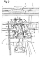
- Conveyor belts 5 and 6 each have a return part that is always indicated by 11 ( Fig. 2 ).
- the drive takes place on this return part.
- This drive is indicated in its entirety by 12.
- the drive consists of a drive motor 13 that drives a drive roller 15 via a transmission 14.
- the return part is wrapped around the drive roller 15.
- the angle is at least 180° and more particularly more than 270° of the arc that is described by the drive roller.
- There are pressure rollers 16 and 17. Both are mounted on a tensioning arm 18 that is fixed to the frame with joint 20. Tensioning arms 18 are linked to one another via a rod 31 and springs 32 with stops 33.
- the width of the drive roller 15 shown and the two pressure rollers 16, 17 is greater than that of the return part, so that it is certain that the full width of said return part comes into engagement with said drive roller.
- This construction functions as follows. If the belt in Fig. 2 has to be moved to the right in the direction of the arrow, the drive roller 15 is rotated anti-clockwise. As a result of the increase in the tensioning force on the left-hand part of the belt the left-hand pressure roller 17 will move to the left. As a result rod 31 will also move to the left and during a first stage of the travel a gradually increasing pressure will be exerted by the springs 32 on roller 16 in the direction of drive roller 15, as a result of which the belt is clamped increasingly more firmly against the drive roller 15. This pressure is in general sufficient to start and maintain the movement of the belt.
- the drive roller 15 is common for several return parts 11 and the pressure rollers 16, 17 are individual for each return part. In an embodiment with separate drive rollers 15, which is not shown, these drive rollers are permanently joined to a common drive shaft. Because the mechanism with rods 31 and pressure rollers 16, 17 can always be made individual, the optimum tension is always selected for each belt of, for example, each conveyor, or each set of belts for each conveyor (see Fig. 3 ). That is to say, if relatively low loading acts on a conveyor belt during common rotation of roller 15, in the example shown above roller 17 is moved to the left only over a small distance, whilst a much greater force can be applied to an adjacent conveyor belt moved by the same roller 15 because the pressure roller 17 effective for this is moved further to the left.
- a conveyor as described above can be used in a greenhouse or the like and the crop concerned can be transported to the end thereof depending on the requirements.
- FIG. 3 A system consisting of various conveyors as described above is shown diagrammatically in Fig. 3 . Such a system is indicated in its entirety by 24.
- the drive rollers 15 concerned are always driven with drive shafts 26. With such an embodiment all return parts 11 will be permanently pressed onto the drive roller 15 concerned by a pressure roller 16, 17.
- the pressure rollers can optionally be switched off individually per conveyor in some way or other. That is to say when drive motor 25 runs all conveyor belts will be driven, unless the pressure rollers concerned have been switched off. Only those conveyor belts for which the relevant conveyor does not have to be used for a prolonged period will not be driven by switching off the pressure rollers. This switching off can be effected, for example, electrically or manually by engaging on the relevant tensioning arms 18.
- a common take-off conveyor is indicated by 27 as an example.
Landscapes
- Engineering & Computer Science (AREA)
- Mechanical Engineering (AREA)
- Life Sciences & Earth Sciences (AREA)
- Environmental Sciences (AREA)
- Structure Of Belt Conveyors (AREA)
- Attitude Control For Articles On Conveyors (AREA)
- Intermediate Stations On Conveyors (AREA)
Claims (11)
- Verfahren umfassend eine Anzahl von Fördergeräten, wobei jedes Fördergerät eine längliche flache Stütze (3) umfasst, mit, darauf angeordnet, einem beweglichen Transportband (5,6) für Objekte, wobei das Transportband ein Rückteil (4) sowie einen Antrieb (12) hat, wobei der Antrieb eine Antriebsrolle (15) und, in jedem Fall, eine Druckrolle (16,17) an jeder Seite der Antriebsrolle (15) hat, wobei die Druckrollen auf einem Dreharm (18) angeordnet und miteinander verbunden sind, worin die Schäfte der Antriebsrolle und der Druckrollen wesentlich parallel sind, wobei die Druckrollen (16,17) an beiden Seiten der Antriebsrolle im Rückteil in der Bewegungsrichtung des Rückteils sind und das Transportband derartig angeordnet ist, dass es rund um die Antriebsrolle über zumindest 180° und rund um jede der Druckrollen über zumindest 90° geführt wird, und wobei die Antriebsrollen (15,16,17) derartig verbunden sind, dass wenn die Zugkraft im Rückteil zugenommen hat, dieses Teil die betreffende Druckrolle von der Antriebsrolle weg bewegt und die andere Druckrolle in die Richtung zur Antriebsrolle bewegt, mit dem Resultat dass die letztgenannte Druckrolle das Band mit mehr Kraft auf die Antriebsrolle drückt, dadurch gekennzeichnet, dass ein gemeinsamer Antriebsmotor (25) vorgesehen wird, welcher jede der Antriebsrollen (15) antreibt, und wobei der Antrieb (1) für jedes Fördergerät einzeln kontrollierbar ist.
- Verfahren nach Anspruch 1, wobei die Druckrollen (16,17) jede auf einem Dreharm montiert sind und wobei die Dreharme durch eine Verbindungsstange (31) miteinander verbunden sind.
- Verfahren nach einem der vorhergehenden Ansprüche, wobei die Breite der Stütze (3) in der Richtung senkrecht auf der Bewegungsrichtung des Transportbandes (5,6) grösser ist als die Breite des Transportbandes.
- Verfahren nach Anspruch 3, umfassend ein einzelnes Transportband wo die Stütze über jeder Seite des Transportbandes heraus reicht.
- Verfahren nach einem der Ansprüche 3,4, umfassend zwei auf einigem Abstand voneinander gelegene Transportbänder (15,16), wobei die Stütze (13) sich dazwischen befindet.
- Verfahren nach Anspruch 5, umfassend einen gemeinsamen Antriebsmechanismus (12) für die zwei Transportbänder.
- Verfahren nach einem der vorhergehenden Ansprüche, wobei die Objekte Topfpflanzträger (7) umfassen mit einer grösseren Breite als die Breite des Transportbandes.
- Verfahren nach Anspruch 7, wobei die Topfpflanzträger scheibengeformte Träger mit einem Zentralsitz (9) für eine Topfpflanze (10) umfassen.
- Verfahren nach einem der vorhergehenden Ansprüche, wobei die Stütze mit angrenzenden senkrechten Verstärkungskörpern (4) versehen ist.
- Verfahren nach einem der vorhergehenden Ansprüche, wobei die Stütze mit einem versenkten Abschnitt versehen ist.
- Verfahren nach einem der vorhergehenden Ansprüche, das mit einer Zuführung oder einem Abfluss (27) mit den Fördergeräten verbunden ist.
Applications Claiming Priority (2)
| Application Number | Priority Date | Filing Date | Title |
|---|---|---|---|
| NL1024683 | 2003-10-31 | ||
| NL1024683A NL1024683C2 (nl) | 2003-10-31 | 2003-10-31 | Transporteur, alsmede stelsel omvattende een aantal transporteurs. |
Publications (2)
| Publication Number | Publication Date |
|---|---|
| EP1528018A1 EP1528018A1 (de) | 2005-05-04 |
| EP1528018B1 true EP1528018B1 (de) | 2008-05-14 |
Family
ID=34420832
Family Applications (1)
| Application Number | Title | Priority Date | Filing Date |
|---|---|---|---|
| EP04077934A Expired - Lifetime EP1528018B1 (de) | 2003-10-31 | 2004-10-25 | Förderer und Förderanlage mit einer Anzahl derartigen Förderer |
Country Status (4)
| Country | Link |
|---|---|
| EP (1) | EP1528018B1 (de) |
| AT (1) | ATE395277T1 (de) |
| DE (1) | DE602004013701D1 (de) |
| NL (1) | NL1024683C2 (de) |
Families Citing this family (3)
| Publication number | Priority date | Publication date | Assignee | Title |
|---|---|---|---|---|
| NL1036002C2 (nl) * | 2008-09-30 | 2009-05-26 | Wilfridus Adiranus Barendse | Dubbelwerkende transportband. |
| CN103109698A (zh) * | 2012-11-05 | 2013-05-22 | 南京农业大学 | 基于作物生育期的转栋式智能温室设计工艺 |
| EP3348862A1 (de) * | 2017-01-17 | 2018-07-18 | Siemens Healthcare Diagnostics Products GmbH | Riemenspannersystem |
Family Cites Families (10)
| Publication number | Priority date | Publication date | Assignee | Title |
|---|---|---|---|---|
| US3536185A (en) * | 1968-08-21 | 1970-10-27 | Btu Eng Corp | Furnace conveyor drive |
| IT8123316U1 (it) * | 1981-10-27 | 1983-04-27 | Marchetti Augusto | Bancale per il supporto e l'avanzamento delle scatole in una macchina per la chiusura e/o la sigillatura di scatole parallelepipede. |
| DE3734560A1 (de) * | 1987-10-13 | 1989-04-27 | Max Doerr | Foerdereinrichtung |
| DE4205499A1 (de) * | 1992-02-22 | 1993-08-26 | Schlafhorst & Co W | Sperre fuer spulen oder spulenhuelsen tragende, voneinander unabhaengige caddy's |
| NL9400284A (nl) * | 1994-02-22 | 1995-10-02 | Damsigt Bv | Transportsysteem voor potplanten. |
| MY120230A (en) * | 1997-08-08 | 2005-09-30 | Maruyasu Kikai Kk | Curved belt conveyor |
| JP3545975B2 (ja) * | 1999-08-20 | 2004-07-21 | マルヤス機械株式会社 | ベルトコンベア |
| DE10125854A1 (de) * | 2001-05-25 | 2002-11-28 | Montech Ag Derendingen | Transporteinrichtung, insbesondere Transportband |
| JP3848578B2 (ja) * | 2002-01-30 | 2006-11-22 | マルヤス機械株式会社 | ベルトコンベア |
| NL1021196C2 (nl) * | 2002-07-31 | 2004-02-18 | Wps Horti Systems B V | Aandrijf-span-samenstel voor een band alsmede bandstelsel omvattende een dergelijk samenstel. |
-
2003
- 2003-10-31 NL NL1024683A patent/NL1024683C2/nl not_active IP Right Cessation
-
2004
- 2004-10-25 DE DE602004013701T patent/DE602004013701D1/de not_active Expired - Fee Related
- 2004-10-25 AT AT04077934T patent/ATE395277T1/de not_active IP Right Cessation
- 2004-10-25 EP EP04077934A patent/EP1528018B1/de not_active Expired - Lifetime
Also Published As
| Publication number | Publication date |
|---|---|
| NL1024683C2 (nl) | 2005-05-03 |
| DE602004013701D1 (de) | 2008-06-26 |
| EP1528018A1 (de) | 2005-05-04 |
| ATE395277T1 (de) | 2008-05-15 |
Similar Documents
| Publication | Publication Date | Title |
|---|---|---|
| US4264002A (en) | Divider switch for roller conveyors | |
| US4798275A (en) | Line-shaft conveyor diverter | |
| US5634551A (en) | Method and apparatus for regulating the advancing movement of articles, for example in installations for the automatic packaging of food products | |
| US5117961A (en) | Conveying apparatus and article diverter | |
| US20020092734A1 (en) | Right angle power transfer | |
| EP1235728B1 (de) | Vorrichtung zum steuern des durchflusses von artikeln | |
| US5435239A (en) | Conditioning roller assembly | |
| CA2222438A1 (en) | Conveyor system with passive roller transfer assembly | |
| EP1231166A1 (de) | Motorangetriebene Förderrolle | |
| US6296107B1 (en) | Individual caterpillar, in particular for take-off devices, and take-off device for elongate components | |
| CA2331246A1 (en) | Conveying device | |
| US6223888B1 (en) | Accumulation conveyor | |
| US20030155212A1 (en) | U-shaped accumulator device with endless belts | |
| US4333301A (en) | Roll wrapping arrangement | |
| CA2367952A1 (en) | Device and method for unwinding reels of web material | |
| US6273196B1 (en) | Apparatus and method for the stacking of cut grass sods | |
| US4880099A (en) | Tilting reversible belt transfer mechanism | |
| CN212268590U (zh) | 重型一体式皮带机 | |
| EP0008933A1 (de) | Sammelförderer | |
| EP1528018A1 (de) | Förderer und Förderanlage mit einer Anzahl derartigen Förderer | |
| WO2014139684A1 (en) | Apparatus and method for a conveyor with a catenary in the return path | |
| US6062376A (en) | Zero back-pressure conveyor system | |
| WO2000075055A1 (en) | Conveyor transfer assembly | |
| CA2024522A1 (en) | Chain conveyor and pallet | |
| US6237755B1 (en) | Chain drive with adjustable friction |
Legal Events
| Date | Code | Title | Description |
|---|---|---|---|
| PUAI | Public reference made under article 153(3) epc to a published international application that has entered the european phase |
Free format text: ORIGINAL CODE: 0009012 |
|
| AK | Designated contracting states |
Kind code of ref document: A1 Designated state(s): AT BE BG CH CY CZ DE DK EE ES FI FR GB GR HU IE IT LI LU MC NL PL PT RO SE SI SK TR |
|
| AX | Request for extension of the european patent |
Extension state: AL HR LT LV MK |
|
| 17P | Request for examination filed |
Effective date: 20051101 |
|
| AKX | Designation fees paid |
Designated state(s): AT BE BG CH CY CZ DE DK EE ES FI FR GB GR HU IE IT LI LU MC NL PL PT RO SE SI SK TR |
|
| GRAP | Despatch of communication of intention to grant a patent |
Free format text: ORIGINAL CODE: EPIDOSNIGR1 |
|
| GRAS | Grant fee paid |
Free format text: ORIGINAL CODE: EPIDOSNIGR3 |
|
| GRAA | (expected) grant |
Free format text: ORIGINAL CODE: 0009210 |
|
| AK | Designated contracting states |
Kind code of ref document: B1 Designated state(s): AT BE BG CH CY CZ DE DK EE ES FI FR GB GR HU IE IT LI LU MC NL PL PT RO SE SI SK TR |
|
| REG | Reference to a national code |
Ref country code: GB Ref legal event code: FG4D |
|
| REG | Reference to a national code |
Ref country code: CH Ref legal event code: EP |
|
| REG | Reference to a national code |
Ref country code: IE Ref legal event code: FG4D Free format text: LANGUAGE OF EP DOCUMENT: FRENCH |
|
| REF | Corresponds to: |
Ref document number: 602004013701 Country of ref document: DE Date of ref document: 20080626 Kind code of ref document: P |
|
| PG25 | Lapsed in a contracting state [announced via postgrant information from national office to epo] |
Ref country code: SI Free format text: LAPSE BECAUSE OF FAILURE TO SUBMIT A TRANSLATION OF THE DESCRIPTION OR TO PAY THE FEE WITHIN THE PRESCRIBED TIME-LIMIT Effective date: 20080514 |
|
| PG25 | Lapsed in a contracting state [announced via postgrant information from national office to epo] |
Ref country code: ES Free format text: LAPSE BECAUSE OF FAILURE TO SUBMIT A TRANSLATION OF THE DESCRIPTION OR TO PAY THE FEE WITHIN THE PRESCRIBED TIME-LIMIT Effective date: 20080825 Ref country code: FI Free format text: LAPSE BECAUSE OF FAILURE TO SUBMIT A TRANSLATION OF THE DESCRIPTION OR TO PAY THE FEE WITHIN THE PRESCRIBED TIME-LIMIT Effective date: 20080514 |
|
| PG25 | Lapsed in a contracting state [announced via postgrant information from national office to epo] |
Ref country code: AT Free format text: LAPSE BECAUSE OF FAILURE TO SUBMIT A TRANSLATION OF THE DESCRIPTION OR TO PAY THE FEE WITHIN THE PRESCRIBED TIME-LIMIT Effective date: 20080514 Ref country code: PL Free format text: LAPSE BECAUSE OF FAILURE TO SUBMIT A TRANSLATION OF THE DESCRIPTION OR TO PAY THE FEE WITHIN THE PRESCRIBED TIME-LIMIT Effective date: 20080514 |
|
| PG25 | Lapsed in a contracting state [announced via postgrant information from national office to epo] |
Ref country code: CZ Free format text: LAPSE BECAUSE OF FAILURE TO SUBMIT A TRANSLATION OF THE DESCRIPTION OR TO PAY THE FEE WITHIN THE PRESCRIBED TIME-LIMIT Effective date: 20080514 Ref country code: DK Free format text: LAPSE BECAUSE OF FAILURE TO SUBMIT A TRANSLATION OF THE DESCRIPTION OR TO PAY THE FEE WITHIN THE PRESCRIBED TIME-LIMIT Effective date: 20080514 Ref country code: PT Free format text: LAPSE BECAUSE OF FAILURE TO SUBMIT A TRANSLATION OF THE DESCRIPTION OR TO PAY THE FEE WITHIN THE PRESCRIBED TIME-LIMIT Effective date: 20081014 Ref country code: SE Free format text: LAPSE BECAUSE OF FAILURE TO SUBMIT A TRANSLATION OF THE DESCRIPTION OR TO PAY THE FEE WITHIN THE PRESCRIBED TIME-LIMIT Effective date: 20080814 |
|
| PG25 | Lapsed in a contracting state [announced via postgrant information from national office to epo] |
Ref country code: RO Free format text: LAPSE BECAUSE OF FAILURE TO SUBMIT A TRANSLATION OF THE DESCRIPTION OR TO PAY THE FEE WITHIN THE PRESCRIBED TIME-LIMIT Effective date: 20080514 Ref country code: SK Free format text: LAPSE BECAUSE OF FAILURE TO SUBMIT A TRANSLATION OF THE DESCRIPTION OR TO PAY THE FEE WITHIN THE PRESCRIBED TIME-LIMIT Effective date: 20080514 Ref country code: BE Free format text: LAPSE BECAUSE OF FAILURE TO SUBMIT A TRANSLATION OF THE DESCRIPTION OR TO PAY THE FEE WITHIN THE PRESCRIBED TIME-LIMIT Effective date: 20080514 |
|
| PLBE | No opposition filed within time limit |
Free format text: ORIGINAL CODE: 0009261 |
|
| STAA | Information on the status of an ep patent application or granted ep patent |
Free format text: STATUS: NO OPPOSITION FILED WITHIN TIME LIMIT |
|
| 26N | No opposition filed |
Effective date: 20090217 |
|
| PG25 | Lapsed in a contracting state [announced via postgrant information from national office to epo] |
Ref country code: BG Free format text: LAPSE BECAUSE OF FAILURE TO SUBMIT A TRANSLATION OF THE DESCRIPTION OR TO PAY THE FEE WITHIN THE PRESCRIBED TIME-LIMIT Effective date: 20080814 Ref country code: EE Free format text: LAPSE BECAUSE OF FAILURE TO SUBMIT A TRANSLATION OF THE DESCRIPTION OR TO PAY THE FEE WITHIN THE PRESCRIBED TIME-LIMIT Effective date: 20080514 |
|
| PG25 | Lapsed in a contracting state [announced via postgrant information from national office to epo] |
Ref country code: MC Free format text: LAPSE BECAUSE OF NON-PAYMENT OF DUE FEES Effective date: 20081031 |
|
| REG | Reference to a national code |
Ref country code: CH Ref legal event code: PL |
|
| GBPC | Gb: european patent ceased through non-payment of renewal fee |
Effective date: 20081025 |
|
| REG | Reference to a national code |
Ref country code: IE Ref legal event code: MM4A |
|
| REG | Reference to a national code |
Ref country code: FR Ref legal event code: ST Effective date: 20090630 |
|
| PG25 | Lapsed in a contracting state [announced via postgrant information from national office to epo] |
Ref country code: IT Free format text: LAPSE BECAUSE OF FAILURE TO SUBMIT A TRANSLATION OF THE DESCRIPTION OR TO PAY THE FEE WITHIN THE PRESCRIBED TIME-LIMIT Effective date: 20080514 Ref country code: DE Free format text: LAPSE BECAUSE OF NON-PAYMENT OF DUE FEES Effective date: 20090501 |
|
| PG25 | Lapsed in a contracting state [announced via postgrant information from national office to epo] |
Ref country code: CH Free format text: LAPSE BECAUSE OF NON-PAYMENT OF DUE FEES Effective date: 20081031 Ref country code: FR Free format text: LAPSE BECAUSE OF NON-PAYMENT OF DUE FEES Effective date: 20081031 Ref country code: IE Free format text: LAPSE BECAUSE OF NON-PAYMENT OF DUE FEES Effective date: 20081025 Ref country code: LI Free format text: LAPSE BECAUSE OF NON-PAYMENT OF DUE FEES Effective date: 20081031 |
|
| PG25 | Lapsed in a contracting state [announced via postgrant information from national office to epo] |
Ref country code: GB Free format text: LAPSE BECAUSE OF NON-PAYMENT OF DUE FEES Effective date: 20081025 |
|
| PGFP | Annual fee paid to national office [announced via postgrant information from national office to epo] |
Ref country code: DE Payment date: 20090423 Year of fee payment: 5 |
|
| PG25 | Lapsed in a contracting state [announced via postgrant information from national office to epo] |
Ref country code: LU Free format text: LAPSE BECAUSE OF NON-PAYMENT OF DUE FEES Effective date: 20081025 Ref country code: CY Free format text: LAPSE BECAUSE OF FAILURE TO SUBMIT A TRANSLATION OF THE DESCRIPTION OR TO PAY THE FEE WITHIN THE PRESCRIBED TIME-LIMIT Effective date: 20080514 Ref country code: HU Free format text: LAPSE BECAUSE OF FAILURE TO SUBMIT A TRANSLATION OF THE DESCRIPTION OR TO PAY THE FEE WITHIN THE PRESCRIBED TIME-LIMIT Effective date: 20081115 Ref country code: DE Free format text: LAPSE BECAUSE OF NON-PAYMENT OF DUE FEES Effective date: 20100501 |
|
| PG25 | Lapsed in a contracting state [announced via postgrant information from national office to epo] |
Ref country code: TR Free format text: LAPSE BECAUSE OF FAILURE TO SUBMIT A TRANSLATION OF THE DESCRIPTION OR TO PAY THE FEE WITHIN THE PRESCRIBED TIME-LIMIT Effective date: 20080514 |
|
| PG25 | Lapsed in a contracting state [announced via postgrant information from national office to epo] |
Ref country code: GR Free format text: LAPSE BECAUSE OF FAILURE TO SUBMIT A TRANSLATION OF THE DESCRIPTION OR TO PAY THE FEE WITHIN THE PRESCRIBED TIME-LIMIT Effective date: 20080815 |
|
| REG | Reference to a national code |
Ref country code: NL Ref legal event code: RC Free format text: DETAILS LICENCE OR PLEDGE: RIGHT OF PLEDGE, ESTABLISHED Name of requester: ABN AMRO BANK N.V. Effective date: 20180918 |
|
| PGFP | Annual fee paid to national office [announced via postgrant information from national office to epo] |
Ref country code: NL Payment date: 20201021 Year of fee payment: 17 |
|
| REG | Reference to a national code |
Ref country code: NL Ref legal event code: HC Owner name: CODEMA EMEA B.V.; NL Free format text: DETAILS ASSIGNMENT: CHANGE OF OWNER(S), CHANGE OF OWNER(S) NAME; FORMER OWNER NAME: W/M SYSTEMS B.V. Effective date: 20210702 |
|
| REG | Reference to a national code |
Ref country code: NL Ref legal event code: MM Effective date: 20211101 |
|
| PG25 | Lapsed in a contracting state [announced via postgrant information from national office to epo] |
Ref country code: NL Free format text: LAPSE BECAUSE OF NON-PAYMENT OF DUE FEES Effective date: 20211101 |