EP1527961A1 - Gassackrückhaltesystem - Google Patents
Gassackrückhaltesystem Download PDFInfo
- Publication number
- EP1527961A1 EP1527961A1 EP04023037A EP04023037A EP1527961A1 EP 1527961 A1 EP1527961 A1 EP 1527961A1 EP 04023037 A EP04023037 A EP 04023037A EP 04023037 A EP04023037 A EP 04023037A EP 1527961 A1 EP1527961 A1 EP 1527961A1
- Authority
- EP
- European Patent Office
- Prior art keywords
- gas bag
- restraint system
- spring
- module
- hook
- Prior art date
- Legal status (The legal status is an assumption and is not a legal conclusion. Google has not performed a legal analysis and makes no representation as to the accuracy of the status listed.)
- Granted
Links
Images

Classifications
-
- B—PERFORMING OPERATIONS; TRANSPORTING
- B60—VEHICLES IN GENERAL
- B60R—VEHICLES, VEHICLE FITTINGS, OR VEHICLE PARTS, NOT OTHERWISE PROVIDED FOR
- B60R21/00—Arrangements or fittings on vehicles for protecting or preventing injuries to occupants or pedestrians in case of accidents or other traffic risks
- B60R21/02—Occupant safety arrangements or fittings, e.g. crash pads
- B60R21/16—Inflatable occupant restraints or confinements designed to inflate upon impact or impending impact, e.g. air bags
- B60R21/20—Arrangements for storing inflatable members in their non-use or deflated condition; Arrangement or mounting of air bag modules or components
- B60R21/203—Arrangements for storing inflatable members in their non-use or deflated condition; Arrangement or mounting of air bag modules or components in steering wheels or steering columns
- B60R21/2035—Arrangements for storing inflatable members in their non-use or deflated condition; Arrangement or mounting of air bag modules or components in steering wheels or steering columns using modules containing inflator, bag and cover attachable to the steering wheel as a complete sub-unit
- B60R21/2037—Arrangements for storing inflatable members in their non-use or deflated condition; Arrangement or mounting of air bag modules or components in steering wheels or steering columns using modules containing inflator, bag and cover attachable to the steering wheel as a complete sub-unit the module or a major component thereof being yieldably mounted, e.g. for actuating the horn switch or for protecting the driver in a non-deployment situation
Definitions
- the invention relates to an airbag restraint system according to the preamble of Claim 1.
- Such a restraint system is usually integrated in the vehicle steering wheel.
- an airbag module by a latching connection with the steering wheel skeleton connected, which must be solvable again.
- There are several locking connections have been proposed, inter alia, hairpin-shaped springs in which For example, one leg attached and the other leg elastically deflectable is to interlock in a groove of a latching hook.
- hairpin-shaped springs in which For example, one leg attached and the other leg elastically deflectable is to interlock in a groove of a latching hook.
- a large, annular single spring conceived, the more Locking catch locking behind engages.
- the object of the invention is to provide an airbag restraint system, in the spring is stored to save space, just locked, a large Preload allowed and especially has a large spring travel. This task is achieved by an airbag restraint system according to claim 1.
- the gas bag restraint system has a spring with a storage section and a hook-side locking portion.
- the size Deflection of the locking portion is by a wound section reached between storage section and locking section.
- This gewikkelte Section allows for extreme travel and high preload. These two factors in turn allow the spring and the hook with a to carry out low construction costs especially space-saving. In the state of Technique were small spring and thus locking paths required.
- the invention also provides an extremely secure locking by a longer spring and locking path.
- the locking portion is formed into a bracket, which gives it a higher stability and allows the bracket mounted in the Condition of the system embraces the hook, similar to a sling. This creates additional security for the attachment of the system according to the invention.
- the spring is similar to the spring in FIG executed a mousetrap, ie with a storage section, the two free Ends of the springs has. These each go in a separate, wrapped Section about.
- the spring extends from the two wound sections then to the locking portion, which, as I said be bow-shaped can.
- This type of spring is also called DoppelMechfeder with Haamadelriv. It offers a large deflection between locking section and Storage section. These sections pivot about an imaginary axis, the passes through the wound section.
- a simple attachment of the spring results from deformed sheet metal sections on the module or on the vehicle part, which are the storage sections terminals.
- the usual gas bag module in the vehicle steering wheel is a so-called Floating-Hom module. This means the module is in the steering wheel axle direction slidable to close a horn circuit.
- the gas bag module often with an intermediate plate running between the vehicle (here the steering wheel) and a module housing sitting.
- the spring can be used to attach the intermediate plate to the vehicle or be provided for attachment of the module housing to the intermediate plate.
- the attachment of the module on Vehicle as the spring as I said is very stable and high security for the Rasttagen offers.
- the spring can be fastened on the vehicle side be to lock with a hook on the module, or, preferably, at the Attached intermediate plate to a preferably on the steering wheel skeleton attack molded hook.
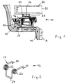
- FIG. 1 shows a steering wheel-integrated gas bag restraint system.
- the Steering wheel is symbolized by a steering wheel skeleton 10.
- the steering wheel has one Steering wheel axle A.
- To the steering wheel skeleton are in the area of the steering wheel hub on two diametrically opposite locations upwardly projecting hooks 12 in one piece formed.
- a gas bag module 14 is attached, which is designed as a floating horn module.
- This latching connection comprises the hook 12 and the module side preassembled springs 16, one of which is shown in Figure 2.
- the spring 16 is a feather similar to that used in a mousetrap.
- the Spring 16 includes two free ends 18 which are linear and angled Have end portions 20. The ends 18 together with their end portions 20 form the Storage section of the spring 16. The ends 18 each go into a separate cylindrically wound section 22 via. The spring wire from which the spring 16 is finally made by the wound portions 22 in a Bracket 24 via which forms the locking portion of the spring.
- the two springs 16 are attached to an intermediate plate 26 (see Figure 3).
- the end portions 20 penetrate two approximately the diameter the spring 16 corresponding large openings in the intermediate plate 26.
- Zur additional attachment flap-shaped sheet metal sections 28 at the Intermediate plate 26 formed to grip the free ends 18.
- the gewikkelten Sections 22 are still above the intermediate plate 26, the bracket 24th but extends through a slot-shaped opening in the intermediate plate 26th down to preside over this.
- the wound, cylindrical Sections define an imaginary pivot axis passing therethrough, To which the bracket 24 is widely pivoted.
- a plurality of return springs 30th fastened, which extend up to a module housing 32 in which an airbag 34 is housed.
- a module housing 32 On the underside of the module housing 32 four are close to the Return springs 30 arranged Horn contacts 36 arranged with mating contacts 38 can be brought into contact when the module housing 32 from Driver in the direction of the axis A and against the force of the return springs 30th is pressed down to close a horn circuit.
- latching connections provided, which can be made similar to those for attachment the intermediate plate 26 on the steering wheel skeleton 10th
- the gas bag module 14 is a preassembled unit from the down two bracket 24 protrude when the gas bag module 14 from above into the cup-shaped Recording in the region of the steering wheel hub is pressed for mounting.
- the Brackets 24 migrate in this assembly on an upper ramp surface 40 each Hook 12 along and are, with reference to Figure 1, in the direction of the axis A. pivoted, under elastic deformation of the spring 16. After reaching the radially innermost point of the hook 12 snap the bracket 24 abruptly outside and behind and engage around the associated hook 12th
- each bracket 24 by a tool back inside be deflected.
- the intermediate plate 26 is fixed in position in the direction A, is usually another elastic element between the intermediate plate 26 and the steering wheel skeleton 10 provided.
- the hooks 12 and the springs 16 form one provided for the gas bag module 14 Fastening device, which is inside the module 14 or between Module and a vehicle part as in the present case the steering wheel skeleton 10 act can.
Landscapes
- Engineering & Computer Science (AREA)
- Mechanical Engineering (AREA)
- Air Bags (AREA)
Abstract
Description
- Figur 1 eine Querschnittsansicht durch eine linke Hälfte eines erfindungsgemäßen Gassackrückhaltesystems, das lenkradintegriert ist,
- Figur 2 eine perspektivische Ansicht einer der beiden an der Zwischenplatte nach Figur 3 befestigten Federn und
- Figur 3 eine perspektivische Draufsicht auf die unter dem Modulgehäuse sitzende Zwischenplatte.
Claims (10)
- Gassackrückhaltesystem mit
einem Gassackmodul (14) und
einer Befestigungsvorrichtung für das Gassackmodul (14),
wenigstens eine mit einem Haken (12) bei der Montage in Rastverbindung kommende Feder (16) aufweist,
dadurch gekennzeichnet, daß die Feder (16) einen Lagerungsabschnitt und einen hakenseitigen Verriegelungsabschnitt sowie wenigstens einen dazwischen vorgesehenen gewickelten Abschnitt (22) aufweist. - Gassackrückhaltesystem nach Anspruch 1, dadurch gekennzeichnet, daß der Verriegelungsabschnitt zu einem Bügel (24) geformt ist.
- Gassackrückhaltesystem nach Anspruch 2, dadurch gekennzeichnet, daß der Bügel (24) in montiertem Zustand des Systems den Haken (12) umgreift.
- Gassackrückhaltesystem nach einem der vorhergehenden Ansprüche, dadurch gekennzeichnet, daß der Lagerungsabschnitt zwei freie Enden (18) der Feder (16) aufweist, die jeweils in einen separaten, gewickelten Abschnitt (22) und die gewickelten Abschnitte (22) wiederum in den Verriegelungsabschnitt übergehen.
- Gassackrückhaltesystem nach einem der vorhergehenden Ansprüche, dadurch gekennzeichnet, daß der Lagerungsabschnitt durch umgeformte Blechabschnitte (28) am Modul (14) oder an einem Fahrzeugteil gehalten ist.
- Gassackrückhaltesystem nach einem der vorhergehenden Ansprüche, dadurch gekennzeichnet, daß das Gassackmodul (14) eine Zwischenplatte (26) zwischen dem Fahrzeugteil und einem Modulgehäuse (32) aufweist und auf der Zwischenplatte (26) die Feder (16) vormontiert ist.
- Gassackrückhaltesystem nach Anspruch 6, dadurch gekennzeichnet, daß es in ein Fahrzeuglenkrad integriert ist.
- Gassackrückhaltesystem nach Anspruch 7, dadurch gekennzeichnet, daß der Haken (12) einstückiger Bestandteil eines Lenkradskeletts (10) ist.
- Gassackrückhaltesystem nach Anspruch 7 oder 8, dadurch gekennzeichnet, daß das Modulgehäuse (32) relativ zur Zwischenplatte (26) zum Schließen eines Hupenschaltkreises verschieblich gelagert ist.
- Gassackrückhaltesystem nach einem der vorhergehenden Ansprüche, dadurch gekennzeichnet, daß der Haken (12) Teil der Befestigungsvorrichtung ist.
Applications Claiming Priority (2)
| Application Number | Priority Date | Filing Date | Title |
|---|---|---|---|
| DE20316519U DE20316519U1 (de) | 2003-10-27 | 2003-10-27 | Gassackrückhaltesystem |
| DE20316519U | 2003-10-27 |
Publications (2)
| Publication Number | Publication Date |
|---|---|
| EP1527961A1 true EP1527961A1 (de) | 2005-05-04 |
| EP1527961B1 EP1527961B1 (de) | 2006-11-02 |
Family
ID=31984653
Family Applications (1)
| Application Number | Title | Priority Date | Filing Date |
|---|---|---|---|
| EP04023037A Expired - Lifetime EP1527961B1 (de) | 2003-10-27 | 2004-09-28 | Gassackrückhaltesystem |
Country Status (4)
| Country | Link |
|---|---|
| US (1) | US7469921B2 (de) |
| EP (1) | EP1527961B1 (de) |
| DE (2) | DE20316519U1 (de) |
| ES (1) | ES2274368T3 (de) |
Families Citing this family (4)
| Publication number | Priority date | Publication date | Assignee | Title |
|---|---|---|---|---|
| US7185915B2 (en) * | 2003-02-27 | 2007-03-06 | Toyoda Gosei Co., Ltd. | Steering wheel incorporating air bag device |
| DE202005013383U1 (de) * | 2005-08-24 | 2006-02-09 | Trw Automotive Safety Systems Gmbh | Fahrzeuglenkrad mit Gassackmodul |
| DE202010016004U1 (de) * | 2010-12-01 | 2012-03-02 | Dalphi Metal España S.A. | Befestigungsvorrichtung für ein Gassackmodul |
| KR20240033489A (ko) * | 2022-09-05 | 2024-03-12 | 현대자동차주식회사 | 스티어링휠과, 그 스티어링휠의 댐퍼유닛 |
Citations (5)
| Publication number | Priority date | Publication date | Assignee | Title |
|---|---|---|---|---|
| US5380037A (en) * | 1993-10-25 | 1995-01-10 | General Motors Corporation | Snap-in inflatable restraint module mounting mechanism including latch elements |
| WO2000074980A1 (de) * | 1999-06-04 | 2000-12-14 | Takata-Petri Ag | Lenkrad |
| EP1167132A2 (de) * | 2000-06-27 | 2002-01-02 | Toyoda Gosei Co., Ltd. | Struktur zum Einbau eines Airbag-Moduls |
| EP1354772A2 (de) * | 2002-04-16 | 2003-10-22 | Takata-Petri AG | Kraftfahrzeugbaugruppe |
| US20040169358A1 (en) * | 2003-02-27 | 2004-09-02 | Yoshiyuki Fujita | Steering wheel incorporating air bag device |
Family Cites Families (9)
| Publication number | Priority date | Publication date | Assignee | Title |
|---|---|---|---|---|
| DE3926153A1 (de) * | 1989-08-08 | 1991-02-14 | Ottmar Haberkern | Bildtongeraet mit einklappbarem flachbildschirm |
| US6237944B1 (en) * | 1999-09-30 | 2001-05-29 | Delphi Technologies, Inc. | Mounting mechanism for inflatable restraint system |
| JP2001213259A (ja) * | 2000-02-03 | 2001-08-07 | Toyoda Gosei Co Ltd | エアバッグ装置を備えたステアリングホイール |
| US6276711B1 (en) * | 2000-03-27 | 2001-08-21 | Breed Automotive Technology, Inc. | Quick disconnect feature for snap-in driver air bag module |
| US6325408B1 (en) * | 2000-05-15 | 2001-12-04 | Breed Automotive Technology, Inc. | Air bag attachment arrangement |
| DE10157043A1 (de) | 2001-11-21 | 2003-06-18 | Opel Adam Ag | Mittel zur Befestigung eines Airbagmoduls in einem Kraftfahrzeug |
| GB2385834A (en) * | 2002-03-01 | 2003-09-03 | Autoliv Dev | Air bag mounting arrangement on vehicle steering wheel |
| US7059631B2 (en) * | 2003-04-29 | 2006-06-13 | Toyoda Gosei Co., Ltd. | Method and apparatus for coupling a driver's side airbag to a steering wheel |
| US7055854B2 (en) * | 2004-03-03 | 2006-06-06 | Autoliv Asp, Inc. | Snap-in castanet airbag module for a vehicular steering wheel |
-
2003
- 2003-10-27 DE DE20316519U patent/DE20316519U1/de not_active Expired - Lifetime
-
2004
- 2004-09-28 EP EP04023037A patent/EP1527961B1/de not_active Expired - Lifetime
- 2004-09-28 ES ES04023037T patent/ES2274368T3/es not_active Expired - Lifetime
- 2004-09-28 DE DE502004001890T patent/DE502004001890D1/de not_active Expired - Lifetime
- 2004-10-20 US US10/969,544 patent/US7469921B2/en not_active Expired - Fee Related
Patent Citations (5)
| Publication number | Priority date | Publication date | Assignee | Title |
|---|---|---|---|---|
| US5380037A (en) * | 1993-10-25 | 1995-01-10 | General Motors Corporation | Snap-in inflatable restraint module mounting mechanism including latch elements |
| WO2000074980A1 (de) * | 1999-06-04 | 2000-12-14 | Takata-Petri Ag | Lenkrad |
| EP1167132A2 (de) * | 2000-06-27 | 2002-01-02 | Toyoda Gosei Co., Ltd. | Struktur zum Einbau eines Airbag-Moduls |
| EP1354772A2 (de) * | 2002-04-16 | 2003-10-22 | Takata-Petri AG | Kraftfahrzeugbaugruppe |
| US20040169358A1 (en) * | 2003-02-27 | 2004-09-02 | Yoshiyuki Fujita | Steering wheel incorporating air bag device |
Also Published As
| Publication number | Publication date |
|---|---|
| US7469921B2 (en) | 2008-12-30 |
| EP1527961B1 (de) | 2006-11-02 |
| DE502004001890D1 (de) | 2006-12-14 |
| DE20316519U1 (de) | 2004-03-04 |
| ES2274368T3 (es) | 2007-05-16 |
| US20050087962A1 (en) | 2005-04-28 |
Similar Documents
| Publication | Publication Date | Title |
|---|---|---|
| EP0771696B1 (de) | Mittel zur Befestigung eines Airbag-Moduls | |
| EP1216895B1 (de) | Haltevorrichtung | |
| EP3045347B1 (de) | Lagervorrichtung und kopfstütze | |
| DE19725684C2 (de) | Lenkrad mit einem mittels Rastverbindung daran befestigten Airbagmodul | |
| EP0983914B1 (de) | Mittel zur Befestigung eines Gasgenerators in einem Airbagmodul | |
| DE102009040303A1 (de) | Lenkrad mit Airbagvorrichtung | |
| DE4344615A1 (de) | Lenkrad | |
| EP1251043A1 (de) | Baueinheit aus Gassackmodul und Fahrzeuglenkrad | |
| EP1354772B1 (de) | Kraftfahrzeugbaugruppe | |
| EP3209525A1 (de) | Gassackmodul, diffusor für ein gassackmodul sowie fahrzeuginsassen-sicherungssystem | |
| EP2509830B1 (de) | Fahrzeuglenkrad | |
| EP0790153B1 (de) | Einrichtung zum Befestigen eines Gassackmoduls | |
| DE102017209492A1 (de) | Halterung zur Befestigung eines Sensors, insbesondere Radarsensors, an einem Fahrzeug und ein System aus einer Halterung und dem Sensor | |
| EP3587196B1 (de) | Gassackmodul für ein fahrzeuginsassen-rückhaltesystem sowie lenkradbaugruppe mit einem solchen gassackmodul | |
| DE102005017503A1 (de) | Arretiersystem für ein Fahrzeugairbagmodul | |
| WO2020126327A1 (de) | Lenkvorrichtungsbaugruppe für ein kraftfahrzeug | |
| EP1549538A1 (de) | Vorrichtung zur schwingungsdämpfenden anordnung eines aggregats und mit derartigen vorrichtungen ausgestattetes aggregat | |
| EP1527961B1 (de) | Gassackrückhaltesystem | |
| EP1452404B1 (de) | Gassackmodul für Lenkrad | |
| DE102009007201A1 (de) | Scheibenbremse mit einer Federanordnung | |
| EP1757491B1 (de) | Fahrzeuglenkrad mit Gassackmodul | |
| DE10157440A1 (de) | Rasteinrichtung für ein Airbagmodul | |
| DE102018208478A1 (de) | Lagerbuchse für eine Pedaleinrichtung eines Kraftfahrzeugs und eine Pedaleinrichtung mit einer solchen Lagerbuchse | |
| WO1995005959A1 (de) | Befestigungsmittel für eine scheibenwischeranlage | |
| DE102010039899A1 (de) | Vorrichtung zur Befestigung eines Halteteils eines Gassackmoduls eines Fahrzeuginsassen-Rückhaltesystems mit einem Verbindungsteil einer Fahrzeugstruktur |
Legal Events
| Date | Code | Title | Description |
|---|---|---|---|
| PUAI | Public reference made under article 153(3) epc to a published international application that has entered the european phase |
Free format text: ORIGINAL CODE: 0009012 |
|
| AK | Designated contracting states |
Kind code of ref document: A1 Designated state(s): AT BE BG CH CY CZ DE DK EE ES FI FR GB GR HU IE IT LI LU MC NL PL PT RO SE SI SK TR |
|
| AX | Request for extension of the european patent |
Extension state: AL HR LT LV MK |
|
| 17P | Request for examination filed |
Effective date: 20051027 |
|
| AKX | Designation fees paid |
Designated state(s): DE ES FR IT |
|
| GRAP | Despatch of communication of intention to grant a patent |
Free format text: ORIGINAL CODE: EPIDOSNIGR1 |
|
| GRAS | Grant fee paid |
Free format text: ORIGINAL CODE: EPIDOSNIGR3 |
|
| GRAA | (expected) grant |
Free format text: ORIGINAL CODE: 0009210 |
|
| REG | Reference to a national code |
Ref country code: DE Ref legal event code: R081 Ref document number: 502004001890 Country of ref document: DE Owner name: ZF AUTOMOTIVE SAFETY GERMANY GMBH, DE Free format text: FORMER OWNER: TRW AUTOMOTIVE SAFETY SYSTEMS GMBH & CO. KG, 63743 ASCHAFFENBURG, DE |
|
| AK | Designated contracting states |
Kind code of ref document: B1 Designated state(s): DE ES FR IT |
|
| REF | Corresponds to: |
Ref document number: 502004001890 Country of ref document: DE Date of ref document: 20061214 Kind code of ref document: P |
|
| REG | Reference to a national code |
Ref country code: DE Ref legal event code: R096 Ref document number: 502004001890 Country of ref document: DE Effective date: 20061214 |
|
| REG | Reference to a national code |
Ref country code: ES Ref legal event code: FG2A Ref document number: 2274368 Country of ref document: ES Kind code of ref document: T3 |
|
| ET | Fr: translation filed | ||
| PLBE | No opposition filed within time limit |
Free format text: ORIGINAL CODE: 0009261 |
|
| STAA | Information on the status of an ep patent application or granted ep patent |
Free format text: STATUS: NO OPPOSITION FILED WITHIN TIME LIMIT |
|
| 26N | No opposition filed |
Effective date: 20070803 |
|
| REG | Reference to a national code |
Ref country code: DE Ref legal event code: R097 Ref document number: 502004001890 Country of ref document: DE Effective date: 20070803 |
|
| PGFP | Annual fee paid to national office [announced via postgrant information from national office to epo] |
Ref country code: ES Payment date: 20080917 Year of fee payment: 5 |
|
| PGFP | Annual fee paid to national office [announced via postgrant information from national office to epo] |
Ref country code: IT Payment date: 20100922 Year of fee payment: 7 |
|
| REG | Reference to a national code |
Ref country code: ES Ref legal event code: FD2A Effective date: 20110711 |
|
| PG25 | Lapsed in a contracting state [announced via postgrant information from national office to epo] |
Ref country code: ES Free format text: LAPSE BECAUSE OF NON-PAYMENT OF DUE FEES Effective date: 20110629 |
|
| PG25 | Lapsed in a contracting state [announced via postgrant information from national office to epo] |
Ref country code: ES Free format text: LAPSE BECAUSE OF NON-PAYMENT OF DUE FEES Effective date: 20090929 |
|
| PG25 | Lapsed in a contracting state [announced via postgrant information from national office to epo] |
Ref country code: IT Free format text: LAPSE BECAUSE OF NON-PAYMENT OF DUE FEES Effective date: 20110928 |
|
| REG | Reference to a national code |
Ref country code: FR Ref legal event code: PLFP Year of fee payment: 13 |
|
| REG | Reference to a national code |
Ref country code: FR Ref legal event code: PLFP Year of fee payment: 14 |
|
| REG | Reference to a national code |
Ref country code: FR Ref legal event code: PLFP Year of fee payment: 15 |
|
| PGFP | Annual fee paid to national office [announced via postgrant information from national office to epo] |
Ref country code: FR Payment date: 20200925 Year of fee payment: 17 |
|
| REG | Reference to a national code |
Ref country code: DE Ref legal event code: R081 Ref document number: 502004001890 Country of ref document: DE Owner name: ZF AUTOMOTIVE SAFETY GERMANY GMBH, DE Free format text: FORMER OWNER: TRW AUTOMOTIVE SAFETY SYSTEMS GMBH, 63743 ASCHAFFENBURG, DE Ref country code: DE Ref legal event code: R082 Ref document number: 502004001890 Country of ref document: DE Representative=s name: PRINZ & PARTNER MBB PATENTANWAELTE RECHTSANWAE, DE |
|
| PG25 | Lapsed in a contracting state [announced via postgrant information from national office to epo] |
Ref country code: FR Free format text: LAPSE BECAUSE OF NON-PAYMENT OF DUE FEES Effective date: 20210930 |
|
| P01 | Opt-out of the competence of the unified patent court (upc) registered |
Effective date: 20230628 |
|
| PGFP | Annual fee paid to national office [announced via postgrant information from national office to epo] |
Ref country code: DE Payment date: 20230930 Year of fee payment: 20 |
|
| REG | Reference to a national code |
Ref country code: DE Ref legal event code: R071 Ref document number: 502004001890 Country of ref document: DE |