EP1527857B1 - Vorrichtung zum Perforieren einer geführten Kunststofffolie - Google Patents
Vorrichtung zum Perforieren einer geführten Kunststofffolie Download PDFInfo
- Publication number
- EP1527857B1 EP1527857B1 EP20040025185 EP04025185A EP1527857B1 EP 1527857 B1 EP1527857 B1 EP 1527857B1 EP 20040025185 EP20040025185 EP 20040025185 EP 04025185 A EP04025185 A EP 04025185A EP 1527857 B1 EP1527857 B1 EP 1527857B1
- Authority
- EP
- European Patent Office
- Prior art keywords
- main shaft
- rollers
- needle
- foam
- needle rollers
- Prior art date
- Legal status (The legal status is an assumption and is not a legal conclusion. Google has not performed a legal analysis and makes no representation as to the accuracy of the status listed.)
- Expired - Lifetime
Links
- 239000002985 plastic film Substances 0.000 title claims abstract description 16
- 229920006255 plastic film Polymers 0.000 title claims abstract description 16
- 230000007246 mechanism Effects 0.000 title description 11
- 238000004519 manufacturing process Methods 0.000 claims description 10
- 238000000034 method Methods 0.000 abstract description 10
- 239000006260 foam Substances 0.000 description 32
- 239000000463 material Substances 0.000 description 15
- 238000009423 ventilation Methods 0.000 description 9
- 238000005755 formation reaction Methods 0.000 description 5
- 239000007789 gas Substances 0.000 description 5
- 238000013022 venting Methods 0.000 description 5
- 230000015572 biosynthetic process Effects 0.000 description 4
- 238000007789 sealing Methods 0.000 description 4
- 230000004075 alteration Effects 0.000 description 3
- 238000010348 incorporation Methods 0.000 description 3
- 238000004806 packaging method and process Methods 0.000 description 3
- CURLTUGMZLYLDI-UHFFFAOYSA-N Carbon dioxide Chemical compound O=C=O CURLTUGMZLYLDI-UHFFFAOYSA-N 0.000 description 2
- 230000001419 dependent effect Effects 0.000 description 2
- 239000000203 mixture Substances 0.000 description 2
- DHKHKXVYLBGOIT-UHFFFAOYSA-N 1,1-Diethoxyethane Chemical compound CCOC(C)OCC DHKHKXVYLBGOIT-UHFFFAOYSA-N 0.000 description 1
- 229920004943 Delrin® Polymers 0.000 description 1
- 229910000760 Hardened steel Inorganic materials 0.000 description 1
- 208000027418 Wounds and injury Diseases 0.000 description 1
- 239000011354 acetal resin Substances 0.000 description 1
- 229910002092 carbon dioxide Inorganic materials 0.000 description 1
- 239000001569 carbon dioxide Substances 0.000 description 1
- 238000006243 chemical reaction Methods 0.000 description 1
- 238000010276 construction Methods 0.000 description 1
- 230000006378 damage Effects 0.000 description 1
- 230000003247 decreasing effect Effects 0.000 description 1
- 208000014674 injury Diseases 0.000 description 1
- 239000005022 packaging material Substances 0.000 description 1
- 239000002861 polymer material Substances 0.000 description 1
- 229920006324 polyoxymethylene Polymers 0.000 description 1
- 238000002360 preparation method Methods 0.000 description 1
- 229910001220 stainless steel Inorganic materials 0.000 description 1
- 239000010935 stainless steel Substances 0.000 description 1
- 239000000126 substance Substances 0.000 description 1
- XLYOFNOQVPJJNP-UHFFFAOYSA-N water Chemical compound O XLYOFNOQVPJJNP-UHFFFAOYSA-N 0.000 description 1
- 230000003245 working effect Effects 0.000 description 1
Images


Classifications
-
- B—PERFORMING OPERATIONS; TRANSPORTING
- B29—WORKING OF PLASTICS; WORKING OF SUBSTANCES IN A PLASTIC STATE IN GENERAL
- B29C—SHAPING OR JOINING OF PLASTICS; SHAPING OF MATERIAL IN A PLASTIC STATE, NOT OTHERWISE PROVIDED FOR; AFTER-TREATMENT OF THE SHAPED PRODUCTS, e.g. REPAIRING
- B29C44/00—Shaping by internal pressure generated in the material, e.g. swelling or foaming ; Producing porous or cellular expanded plastics articles
- B29C44/34—Auxiliary operations
- B29C44/58—Moulds
- B29C44/588—Moulds with means for venting, e.g. releasing foaming gas
-
- B—PERFORMING OPERATIONS; TRANSPORTING
- B26—HAND CUTTING TOOLS; CUTTING; SEVERING
- B26F—PERFORATING; PUNCHING; CUTTING-OUT; STAMPING-OUT; SEVERING BY MEANS OTHER THAN CUTTING
- B26F1/00—Perforating; Punching; Cutting-out; Stamping-out; Apparatus therefor
- B26F1/24—Perforating by needles or pins
-
- B—PERFORMING OPERATIONS; TRANSPORTING
- B29—WORKING OF PLASTICS; WORKING OF SUBSTANCES IN A PLASTIC STATE IN GENERAL
- B29C—SHAPING OR JOINING OF PLASTICS; SHAPING OF MATERIAL IN A PLASTIC STATE, NOT OTHERWISE PROVIDED FOR; AFTER-TREATMENT OF THE SHAPED PRODUCTS, e.g. REPAIRING
- B29C44/00—Shaping by internal pressure generated in the material, e.g. swelling or foaming ; Producing porous or cellular expanded plastics articles
- B29C44/02—Shaping by internal pressure generated in the material, e.g. swelling or foaming ; Producing porous or cellular expanded plastics articles for articles of definite length, i.e. discrete articles
- B29C44/12—Incorporating or moulding on preformed parts, e.g. inserts or reinforcements
- B29C44/18—Filling preformed cavities
- B29C44/182—Filling flexible bags not having a particular shape
-
- B—PERFORMING OPERATIONS; TRANSPORTING
- B26—HAND CUTTING TOOLS; CUTTING; SEVERING
- B26D—CUTTING; DETAILS COMMON TO MACHINES FOR PERFORATING, PUNCHING, CUTTING-OUT, STAMPING-OUT OR SEVERING
- B26D7/00—Details of apparatus for cutting, cutting-out, stamping-out, punching, perforating, or severing by means other than cutting
- B26D7/20—Cutting beds
- B26D2007/202—Rollers or cylinders being pivoted during operation
-
- B—PERFORMING OPERATIONS; TRANSPORTING
- B26—HAND CUTTING TOOLS; CUTTING; SEVERING
- B26D—CUTTING; DETAILS COMMON TO MACHINES FOR PERFORATING, PUNCHING, CUTTING-OUT, STAMPING-OUT OR SEVERING
- B26D3/00—Cutting work characterised by the nature of the cut made; Apparatus therefor
- B26D3/08—Making a superficial cut in the surface of the work without removal of material, e.g. scoring, incising
- B26D3/085—On sheet material
-
- B—PERFORMING OPERATIONS; TRANSPORTING
- B26—HAND CUTTING TOOLS; CUTTING; SEVERING
- B26D—CUTTING; DETAILS COMMON TO MACHINES FOR PERFORATING, PUNCHING, CUTTING-OUT, STAMPING-OUT OR SEVERING
- B26D5/00—Arrangements for operating and controlling machines or devices for cutting, cutting-out, stamping-out, punching, perforating, or severing by means other than cutting
- B26D5/02—Means for moving the cutting member into its operative position for cutting
-
- B—PERFORMING OPERATIONS; TRANSPORTING
- B26—HAND CUTTING TOOLS; CUTTING; SEVERING
- B26D—CUTTING; DETAILS COMMON TO MACHINES FOR PERFORATING, PUNCHING, CUTTING-OUT, STAMPING-OUT OR SEVERING
- B26D7/00—Details of apparatus for cutting, cutting-out, stamping-out, punching, perforating, or severing by means other than cutting
- B26D7/20—Cutting beds
-
- B—PERFORMING OPERATIONS; TRANSPORTING
- B26—HAND CUTTING TOOLS; CUTTING; SEVERING
- B26D—CUTTING; DETAILS COMMON TO MACHINES FOR PERFORATING, PUNCHING, CUTTING-OUT, STAMPING-OUT OR SEVERING
- B26D7/00—Details of apparatus for cutting, cutting-out, stamping-out, punching, perforating, or severing by means other than cutting
- B26D7/22—Safety devices specially adapted for cutting machines
-
- Y—GENERAL TAGGING OF NEW TECHNOLOGICAL DEVELOPMENTS; GENERAL TAGGING OF CROSS-SECTIONAL TECHNOLOGIES SPANNING OVER SEVERAL SECTIONS OF THE IPC; TECHNICAL SUBJECTS COVERED BY FORMER USPC CROSS-REFERENCE ART COLLECTIONS [XRACs] AND DIGESTS
- Y10—TECHNICAL SUBJECTS COVERED BY FORMER USPC
- Y10T—TECHNICAL SUBJECTS COVERED BY FORMER US CLASSIFICATION
- Y10T83/00—Cutting
- Y10T83/04—Processes
-
- Y—GENERAL TAGGING OF NEW TECHNOLOGICAL DEVELOPMENTS; GENERAL TAGGING OF CROSS-SECTIONAL TECHNOLOGIES SPANNING OVER SEVERAL SECTIONS OF THE IPC; TECHNICAL SUBJECTS COVERED BY FORMER USPC CROSS-REFERENCE ART COLLECTIONS [XRACs] AND DIGESTS
- Y10—TECHNICAL SUBJECTS COVERED BY FORMER USPC
- Y10T—TECHNICAL SUBJECTS COVERED BY FORMER US CLASSIFICATION
- Y10T83/00—Cutting
- Y10T83/929—Tool or tool with support
- Y10T83/9314—Pointed perforators
-
- Y—GENERAL TAGGING OF NEW TECHNOLOGICAL DEVELOPMENTS; GENERAL TAGGING OF CROSS-SECTIONAL TECHNOLOGIES SPANNING OVER SEVERAL SECTIONS OF THE IPC; TECHNICAL SUBJECTS COVERED BY FORMER USPC CROSS-REFERENCE ART COLLECTIONS [XRACs] AND DIGESTS
- Y10—TECHNICAL SUBJECTS COVERED BY FORMER USPC
- Y10T—TECHNICAL SUBJECTS COVERED BY FORMER US CLASSIFICATION
- Y10T83/00—Cutting
- Y10T83/929—Tool or tool with support
- Y10T83/9372—Rotatable type
- Y10T83/9377—Mounting of tool about rod-type shaft
Definitions
- the present invention relates to a mechanism for creating perforations in an advancing film, in particular in the bag film of a foam-in-bag cushion.
- the invention relates to a mechanism that is structured and arranged for attachment to a foam-in-bag cushion producing apparatus, wherein the mechanism is capable of creating perforations in the plies of the foam-in-bag cushions, at any point along the length of the cushions, wherein the perforations are capable of allowing gases to move into and out of the cushions while preventing foam formed in the cushions from escaping.
- Such cushions are typically comprised of opposing sheets of plastic film having their edges sealed and being filled with a foam-forming material.
- the cushions are inserted into the packaging box immediately after their production where the foam is allowed to expand and harden, taking on the shape of the packaging container and the material being packaged.
- U.S. Patent No. 6,131,375 discloses an apparatus for successively forming foam cushions from two reactive foam components that, when mixed together, form an expandable foam, and from two opposing flexible panels that enclose the expandable foam.
- the apparatus advances two opposing film panels across a foam dispensing assembly so that the two panels are on opposite sides of the foam dispensing assembly, which separately dispenses the two reactive foam components into the space between the film panels where the components mix to form the foam.
- the marginal edges of the film panels are sealed, creating a foam-filled bag.
- Slit-formation is a method for providing ventilation that is presently used with the SpeedyPackerTM foam-in-bag packaging system available from Sealed Air Corporation (Saddle Brook, NJ). While ventilation using slit-forming mechanisms is effective at allowing formed gases to escape, the slits have the disadvantage of being large enough in size to allow foam to escape the bag, especially with small size applications, such as continuous foam tubes (CFTs). This is problematic in that the cushions are generally placed in contact with the material to be packaged to allow the cushion to take on the shape of the packaged material. It is undesirable to allow foam escaping the bag to make contact with the packaged materials.
- CFTs continuous foam tubes
- Needle rollers have been used with foam-in-bag cushion producing apparatuses, such as the SpeedyPackerTM system, and have been shown to be effective at providing ventilation while preventing the escape of foam from the bags. Placement of a needle roller in the SpeedyPackerTM system allows for continual venting of the film used to create the bags; however, the current system is limited by its reliance on manual alteration of the system. In other words, with the needle roller in place, vents are always being made, with no variation in the pattern or number of vents created.
- a mechanism structured and arranged for attachment to a foam-in-bag cushion producing apparatus, such as the SpeedyPackerTM , capable of creating perforations in the bag in an automated fashion, such that the mechanism can accommodate any type of bag, at any time, and in any combination.
- a foam-in-bag cushion producing apparatus such as the SpeedyPackerTM
- U.S. Patent No. 5,802,945 discloses an arrangement of needle rollers wherein multiple needle rollers, specifically four needle rollers, are mounted in a rotary frame which is fully rotatable about a central axis. This rotary frame can be rotated so that the desired needle roller is in position for interacting with a brush roller.
- Each needle roller is provided with a mechanism to allow the needle roller to be lifted away from the brush roller and placed back on the brush roller without requiring rotary movement of the entire rotary frame.
- each needle roller mechanism is provided with a spring bias on the shaft ends of each needle roller such that the needle roller is biased radially away from the central axis of the rotary frame and therefore toward the periphery of the rotary frame.
- a needle roller which is in this way biased towards the may be brush roller may be lifted away from the brush roller by a exerting a force against the ends of the shaft on which the particular needle roller is mounted.
- a complicated cam mechanism is mounted to the rotary frame.
- U.S. Patent 4,167,131 discloses an apparatus for perforating an advancing plastic film comprising a frame, a main shaft mounted in the frame so as to be rotatable about a central axis of the main shaft, a needle roller coupled to the main shaft in radially offset position therefrom by being mounted on a secondary shaft fixedly mounted to the main shaft with a pair of arms, wherein the arms extend radially out from the axis of the main shaft, such that rotation of the main shaft through a part of a revolution moves the needle roller through a predetermined arc of motion, wherein the needle roller is arranged to be freely rotatable about an axis of the needle roller, independently of the rotation in the main shaft, an actuator coupled with the main shaft and operable to rotate the main shaft so as to move the needle roller through said arc of motion such that at one end of said arc of motion the needle roller is in an operative position, adjacent the advancing film, engaging and perforating the film, and at an opposite end of said arc of motion, the needle
- the needle roller In the operative position the needle roller is pressed against a backup roller, the backup roller and the needle roller creating a nip to which the advancing film is passed; in the inoperative position the needle roller is moved away from the backup roller by an accurate movement of the arms around the main shaft, wherein the main shaft rotatably supports an idle roller which is used to guide the advancing film into the nip between backup roller and needle roller when the latter is in its operative opposition.
- an apparatus for creating perforations over a defined area through a moving foam-in-bag film at any point along the length of the film comprises a pair of frame plates spaced apart opposite one another, a main shaft extending between the frame plates and mounted so as to be rotatable about a central axis of the main shaft, secondary shafts having central axes and being fixedly mounted to the main shaft in radially offset positions therefrom, needle rollers mounted on each of the secondary shafts so as to be freely rotatable about the secondary shafts, tertiary shafts cantilevered off each frame plate and having free ends, and backup rollers mounted on each of said tertiary shafts such that the backup rollers are freely rotatable about the tertiary shafts, the free ends of which being joined together by a support bar.
- the apparatus also comprises means for rotating the main shaft so as to move the needle rollers between operative and inoperative positions in which the needle rollers are respectively in contact and out of contact with the backup rollers, whereby a film passing between the backup rollers and the needle rollers is perforated by the needle rollers when the needle rollers are in the operative position and is not perforated when the needle rollers are in the inoperative position.
- the perforating apparatus is structured and arranged for attachment to a foam-in-bag cushion production apparatus.
- the apparatus 10 generally comprises a frame on which the remaining portions of the apparatus can be mounted.
- the frame can consist of a pair of frame plates 12 that are advantageously structured for mounting the remaining portions of the apparatus 10 and for allowing the apparatus 10 to be structured and arranged for attachment to an additional apparatus wherein a perforating mechanism would be useful, such as a foam-in-bag cushion production apparatus.
- the frame plates 12 can be connected through use of a support bar 15, which ties the frame plates 12 together and provides additional rigidity to the frame.
- the apparatus 10 is further comprised of a main shaft 18 mounted in the frame, preferentially between the two frame plates 12.
- the main shaft 18 is mounted so as to be rotatable about a central axis extending the length of the main shaft 18.
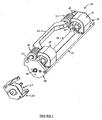
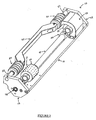
- the needle rollers 35 are partially obstructed from view in FIGURE 1 by a needle roller cover 40; the needle roller 35 is visible in FIGURE 2 , which shows a perspective view of the apparatus 10 with a needle roller cover 40 removed, and in FIGURE 3 , which provides an exploded schematic view of the apparatus 10.
- the needle roller cover 40 limits physical contact with the needle rollers 35 by persons interfacing with the apparatus 10, thereby reducing the risk of possible injury by contact with the needle rollers 35.
- the needle rollers cover 40 provides protection when the needle rollers 35 are in the operative position, the inoperative position, and at all points in between.
- the needle rollers 35 are coupled to the main shaft 18 such that rotation of the main shaft 18 about its axis through part of a revolution moves the needle rollers 35 through a predetermined arc of motion.
- the needle rollers 35 are arranged such that they are freely rotatable about an axis extending the length of the needle rollers 35, and such that its rotation is independent of the rotation of the main shaft 18.
- each needle roller 35 is coupled to the main shaft 18 by being mounted on a secondary shaft 32 such that each needle roller 35 is freely rotatable about the secondary shaft 32.
- the secondary shaft 32 is attached to the main shaft 18 with a pair of needle rollers attachment arms 30, which are fixedly mounted to the main shaft 18, extending radially outward from the axis of the main shaft 18.
- Each needle roller 35 is mounted on the secondary shaft 32 between the needle roller attachment arms 30, which keep the needle roller 35 on the secondary shaft 32 while allowing the needle roller 35 to rotate freely about the secondary shaft 32.
- the secondary shaft 32 is coupled to the main shaft 18 by the arms 30 such that an axis extending the length of the secondary shaft 32 is parallel with the axis of the main shaft 18, but in an offset fashion.
- the secondary shaft 32 preferably is not able to rotate about its axis.
- the apparatus 10 is comprised of two needle rollers 35 mounted on two secondary shafts 32 coupled to the main shaft 18 with two sets of needle roller attachment arms 30.
- the needle rollers 35 can be coupled to the main shaft 18 so as to be symmetrically spaced about a given point of the axis of the main shaft 18, or the needle rollers 35 can be specifically spaced asymmetrically along the axis of the main shaft 18.
- the arms 30 attach the secondary shafts 32 to the main shaft 18 such that the axes of the secondary shafts 32 are always in line with one another.
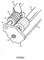
- the needle roller 35 has a substantially cylindrical body with a central bore extending the length of the needle roller 35, parallel with the axis of the needle roller 35. Extending outward radially from the body of the needle roller 35 are pins 37, which are preferentially tapered outward from the body of the needle roller 35.
- the apparatus 10 also comprises two backup rollers 50 mounted in the frame so as to be freely rotatable about an axis extending the length of the backup rollers 50.
- the backup rollers 50 are positioned parallel to the main shaft 18 and is radially offset from the main shaft 18 to be positioned with respect to the predetermined arc of motion of the needle roller 35 such that at one end of the arc of motion, each needle roller 35 is positioned in an inoperative position spaced away from the backup roller 50.
- each needle roller 35 is positioned such that it is in an operative position, adjacent to the associated backup roller 50, so as to form a nip 70 between each needle roller 35 and the associated backup roller 50. It is through this nip 70 that an advancing film passes, and the needle rollers 35, being in the operative position, engage the advancing film, perforating the film.
- the number of backup rollers 50 is equal to the number of needle rollers 35, and in a particularly preferred embodiment, there are two needle rollers 35 and two backup rollers 50.
- the backup rollers 50 are mounted on tertiary shafts 53, having an axis extending the length of the tertiary shafts 53.
- the backup rollers 50 are capable of freely rotating about the axis of the tertiary shafts 53, which are cantilevered off the frame plates 12 having free ends and cannot rotate about their own axis.
- the free ends of the tertiary shafts 53 are joined together by a support bar 55, which adds rigidity and stiffness to the apparatus 10 as well as supporting the free ends of the tertiary shafts 53 holding the backup rollers 50.
- the main shaft 18 is mounted so as to be rotatable about a central axis extending the length of the main shaft 18. Rotation of the main shaft 18 can be performed by any conventional means that would readily be ascertained by one of skill in the art, such as through manual means or automated means.
- a rotary device is coupled to the main shaft 18.
- the rotary device could be, for example, an actuator, such as a motor or a solenoid. It is especially preferred that the actuator be a rotary solenoid 20, as shown in FIGURES 1 and 3 .
- the main shaft 18 is mounted to the frame plate 12 with a shaft cap 60, which fits over the end of the main shaft 18 and into a hole in the frame plate 12 .
- a shaft mounting gasket 62 can also be used according to this embodiment.
- the rotary solenoid 20 engages the main shaft 18 with a solenoid key shaft 22, which fits into a receiving socket 75 in the shaft cap 60, which extends through the frame plate 12.
- the rotary solenoid 20 can be mounted to the frame of the perforating apparatus 10. In a preferred embodiment, however, the rotary solenoid 20 is mounted to the frame of the apparatus into which the perforating apparatus 10 is installed. Such mounting can be carried out through the use of a mounting bracket 23.
- the perforating apparatus 10 can be installed as a unit on a foam-in-bag cushion production apparatus.
- FIGURE 5 provides a perspective view of a foam-in-bag cushion apparatus onto which a perforation apparatus 10 of the present invention has been installed.
- the perforation apparatus 10 is structured and arranged to be capable of being installed onto various types of apparatuses used for preparing a plastic films, especially films wherein perforating of the films would be advantageous, particularly foam-in-bag cushion making apparatuses.
- FIGURE 5 illustrates a preferred embodiment wherein the perforation apparatus 10 is installed onto a SpeedyPackerTM foam-in-bag apparatus 88 (portions of the workings of the SpeedyPackerTM , such as the means for delivering the foam-forming components, are removed to allow a better view of the installed perforating apparatus 10).
- the foam-in-bag apparatus 88 is comprised of a frame 80 onto which the components of the foam-in-bag apparatus 88 are installed.
- the frame 80 includes holes 82 for receiving a shaft (not shown) capable of holding a roll of plastic film to be used in making the foam-in-bag cushions.
- the foam-in-bag apparatus 88 further comprises an upper guide roller 77 and a lower guide roller 79 for moving the plastic film through the foam-in-bag apparatus 88 and maintaining alignment of the film.
- the perforating apparatus 10 is installed above the lower guide roller 79 through attachment of the frame plates 12 to the frame 80 of the foam-in-bag apparatus 88.
- the frame 80 of the foam-in-bag apparatus 88 further comprises a hole 78 through which an actuator, such as the rotary solenoid 20, can engage the main shaft 18, thereby allowing for rotation of the main shaft 18 and subsequent movement of the needle roller 35 into and out of an operative position.
- the foam-in-bag apparatus 88 further comprises a housing 85, in which the electrical and computer components of the machine are maintained.
- the actuating means preferably a rotary solenoid 20
- the actuating means are controlled by the same electronics and computer software used to run the foam-in-bag apparatus 88. This allows for the perforating apparatus 10 to be fully automated.
- the above disclosure of the incorporation of the perforating apparatus 10 into an apparatus for preparing foam-in-bag cushions is not intended to limit the ways in which the perforating apparatus 10 can be incorporated or the type of cushion preparation apparatus into which the perforating apparatus 10 can be incorporated.
- Various apparatuses for forming foam cushions are known, such as those disclosed in U.S. Patent No.
- the actuating means are a rotary solenoid 20 that is coupled to the main shaft 18 and energized and controlled with the electrical and computer components of the apparatus to which it is attached.
- the rotary solenoid 20 is designed such that when it is energized, rotation of the solenoid key shaft 22 causes rotation of the main shaft 18 through part of a revolution, moving each needle roller 35 through a predetermined arc of motion.
- each needle roller 35 is adjacent to the associated backup roller 50, forming a nip 70 therewith and perforating the film passing through the nip 70. In this state, each needle roller 35 is said to be in the operative position.
- each needle roller 35 When power to the rotary solenoid 20 is interrupted, the rotation of the main shaft 18 is disengaged, allowing each needle roller 35 to move back along the predetermined arc of motion to a point away from the backup roller 50 where perforation of the film is stopped. In this state, each needle roller 35 is said to be in the inoperative position.
- Such movement of the needle roller 35 between the operative and inoperative positions can be performed manually.
- the movement of the needle roller 35 between the operative and inoperative positions can also be fully automated, being controlled by the electrical and computer components of the apparatus to which the perforating apparatus 10 is attached.
- Foam-in-bag cushion making apparatuses such as the SpeedyPackerTM
- Foam-in-bag cushion making apparatuses are generally designed to allow for the production of multiple types and sizes of cushions.
- single bags can be prepared, wherein a bag having the bottom and side edges sealed is filled with foam-forming materials before having the top edge sealed and simultaneously cut, freeing the single bag from the remaining sheet of plastic film.
- Such single bags are commonly referred to as wet bags.
- the width of the wet bags is dependent upon the width of the roll of plastic film being used. Common widths for use with the SpeedyPackerTM are 8, 12, and 19 inches.
- the length of the bag is determined by the machine operator and can vary depending upon the specific application. Wet bags are generally only vented in the upper portions of the bag. Therefore, any perforation apparatus used in venting wet bags should advantageously be capable of creating perforations in a specific portion of the bag rather than along the entire length of the bag.
- a CFT is a length of multiple foam-filled bags that are still connected, the bags comprising the CFT being generally smaller in size than a typical wet bag.
- a typical CFT pattern using 19-inch wide film would comprise bags that are approximately five inches in length.
- a CFT is prepared similarly to a wet bag with the exception that when the top of the bag is sealed after introduction of the foam-forming components, it is not cut free from the remaining length of plastic film. Instead, the bag remains attached to the advancing plastic film and another bag is formed immediately thereafter (i.e., the bottom seal for the next bag is made immediately above the top seal of the previous bag).
- the foam-filled bags are connected by lengths of plastic film that are not foam filled.
- the length of film connecting the foam-filled bags is between about 0.25 inches and about 1 inch but can be greater or less than this range depending upon the specified use.
- the optimal length of non-foam-filled film connecting the foam-filled bags for a given specified use would be recognizable to one of ordinary skill in the art.
- the perforating apparatus 10 of the present invention creates the proper amount of venting for any size wet bag, letting gas and air pass into and out of the bag while preventing foam from escaping.
- the apparatus 10 also creates the proper venting for CFTs, which, unlike wet bags, need venting for their entire length to form properly. Because the apparatus 10 is fully automated, it can accommodate any pack at any time and in any combination. Because the actuating means, such as the rotary solenoid 20 , are capable of being controlled by the same electronics and computer software as the foam-in-bag cushion making apparatus, the solenoid 20 can be controlled as an integral component of the foam-in-bag cushion making apparatus.
- the perforating apparatus 10 can function in synchronism with the foam-in-bag cushion making apparatus providing the precise amount of perforating necessary for the size, shape, and type of bag being produced, regardless of the possible combinations (i.e., wet bag, CFT, wet bag, wet bag, CFT, etc.). Further, the perforating apparatus 10 can be left in its operative position for long stretches at a time to accommodate CFTs or it can be used intermittently, such as with wet bags.
- a method for preparing foam-in bag cushions comprises supplying at least one web of film and manipulating the film such that two film portions are in an overlying position, opposite one another.
- the method further comprises sealing the edges of the opposing film portions to form a bag with an interior space capable of receiving a foam-forming material and having one open side for receiving the material.
- the opposing film portions can be formed from a single web of film, manipulated to form overlying portions, or, preferably, from two webs of film supplied simultaneously to be adjacent and in opposition to one another.
- Means for sealing the edges of the film thereby forming a bag with the edges with the exception of one edge can be any means readily envisioned by one of skill in the art.
- the sealing means are such that the sealing of the top edge of one bag simultaneously forms the bottom seal of the next bag.
- a particularly advantageous feature of the perforating apparatus 10 of the present invention is its ability to form various shapes and patterns of perforations.
- one perforation pattern can be set for wet bags while another pattern is set for CFTs, and both types of bags can be produced on the same machine without modifying the machine, even when the production scheme is varied.
- This versatility is due in part to the ability of the movement of the needle roller 35 between the operative and inoperative positions to be performed automatically and under computer control.
- the engagement of the needle rollers 35 with the associated backup rollers 50, and subsequently of the pins 37 of the needle rollers 35 with the film can be controlled such that the engagement is of the precise length of time to produce the exact amount of perforations desired.
- a single machine having the perforating apparatus 10 installed could be set to produce wet bags of a given size having perforations in a precise area of the bag (such as the top half of the bag or the top left quadrant of the bag) and also be set to produce CFTs having perforations along the entire length and width of the bags.
- the formation of the perforations is precisely controlled because the computer is engaging and disengaging the needle roller 35 at the precise time to perforate only where perforations are desired.
- the perforation apparatus 10 of the present invention lies in the number of needle rollers 35 incorporated in the apparatus 10.
- the perforation apparatus 10 is comprised of at least two needle rollers 35.
- the versatility of the perforation apparatus 10 is also due to the physical formation of the needle rollers 35 and the pins 37.
- the type, spacing, and amount of perforations made by the needle rollers 35 can be altered by variations in the pins 37.
- the pins 37 are evenly spaced on the face of the needle rollers 35 forming a repeating pattern.
- pins 37 could be removedly mounted on the needle rollers 35 such that more pins 37 could be added to make more perforations, and, alternately, pins 37 could be removed to make fewer perforations.
- One method for accomplishing this embodiment could be by providing needle rollers 35 with a number of threaded holes whereby pins 37 having threaded shafts could be screwed into the threaded holes until the desired number of pins 37 and desired pattern is achieved.
- Variations to the perforation created by the perforating apparatus 10 can also be due to changes to the pins 37 themselves.
- the pins 37 are metallic in nature and shaped such that they have their greatest width at the base where the pins 37 are in contact with the needle roller 35 and are subsequently tapered outward from the needle roller 35 ending in a sharp point.
- Other formations for the pins could be readily envisaged by one of skill in the art, and could include alterations, such as the pins 37 having a uniform diameter along the majority of their length and tapering to a sharp point only near the tip of the pins 37.
- the pins 37 be constructed of hardened steel as it is necessary that the pins 37 have sufficient strength to perforated multiple layers of plastic film, sufficient durability to function properly for extended lengths of time without needing replacement, and be capable of withstanding possible contact with the foam-forming materials in regard to chemical resistance and non-sticking ability.
- each backup roller 50 is comprised of a hard polymer material having grooves 52 surrounding the circumference of the backup roller 50 and spaced along the width of the backup roller to correspond to the row of pins 37 on the needle roller 35.
- the grooves 52 are designed for receiving the pins 37 on the needle rollers 35 as the pins 37 perforated and pass through the film moving between the backup rollers 50 and the needle rollers 35.
- An especially preferred material for constructing the backup roller is Delrin®, a low wear, low friction acetal resin available from Dupont.
- Backup rollers 50 comprised of different materials can also be used according to the present invention.
- the backup rollers 50 could be comprised of a brush-like material, preferably stiff in nature, capable of supporting the film and receiving the pins 37 as they perforate the film. Further, the backup rollers 50 could be comprised of a durable sponge or foam-like material, again capable of supporting the film and receiving the pins 37 as they perforate the film. Other types of material and backup roller 50 construction could be used according to the present invention and as such would be readily recognizable to one of skill in the art.
Landscapes
- Life Sciences & Earth Sciences (AREA)
- Forests & Forestry (AREA)
- Engineering & Computer Science (AREA)
- Mechanical Engineering (AREA)
- Perforating, Stamping-Out Or Severing By Means Other Than Cutting (AREA)
- Making Paper Articles (AREA)
- Manufacturing Of Printed Circuit Boards (AREA)
- Separation, Sorting, Adjustment, Or Bending Of Sheets To Be Conveyed (AREA)
- Separation Using Semi-Permeable Membranes (AREA)
Claims (14)
- Eine Vorrichtung (10) zum Perforieren einer geführten Kunststofffolie, umfassend:einen Rahmen;eine Hauptwelle (18), die drehbar um eine Mittelachse der Hauptwelle (18) in dem Rahmen angebracht ist;mindestens zwei Nadelrollen (35), die in radial beabstandeter Position von dort mit der Hauptwelle (18) dadurch gekoppet sind, dass sie an einer zweiten Welle (32) angebracht sind, die mit einem Paar Hebeln (30) unbeweglich an die Hauptwelle (18) angebracht sind, wobei die Hebel (30) sich radial von der Achse der Hauptwelle (18) aus erstrecken, so dass eine Drehbewegung der Hauptwelle (18) über einen Teil einer Umdrehung die mindestens zwei Nadelrollen (35) hierdurch über einen vorbestimmten Bewegungsbogen bewegt, wobei die mindestens zwei Nadelrollen (35) so angeordnet sind, dass sie frei drehbar um eine Achse der mindestens zwei Nadelrollen (35) sind, unabhängig von einer Drehung der Hauptwelle (18);einen Antrieb (20), der mit der Hauptwelle (18) gekoppelt ist und dazu betreibbar ist, die Hauptwelle (18) zu drehen, um die mindestens zwei Nadelrollen (35) über den besagten Bewegungsbogen zu bewegen, so dass an einem Ende des Bewegungsbogens die mindestens zwei Nadelrollen (35) in wirksamen Positionen, anliegend an der geführten Folie sind, die Folie erfassend und perforierend, und an dem gegenüberliegenden Ende des Bewegungsbogens die mindestens zwei Nadelrollen (35) in unwirksamen Positionen, beabstandet von der geführten Folie sind; undmindestens zwei Stützrollen (50), die so in dem Rahmen angebracht sind, um frei drehbar um eine Achse der mindestens zwei Stützrollen (50) zu sein, wobei die mindestens zwei Stützrollen (50) an dritten Wellen (53) angebracht sind, wobei die freien Enden der dritten Wellen (53) über eine Haltestange (55) verbunden sind.
- Die Vorrichtung aus Anspruch 1, wobei der Rahmen ein Paar beabstandeter, einander gegenüberliegender Rahmenplatten (12) umfasst.
- Die Vorrichtung aus Anspruch 2, wobei der Rahmen ferner eine Tragestange (15) umfasst, die die Rahmenplatten (12) verbindet.
- Die Vorrichtung aus Anspruch 2, wobei die Hauptwelle (18) sich zwischen den Rahmenplatten (12) erstreckt.
- Die Vorrichtung aus Anspruch 1, wobei die Achse der zweiten Welle (32) parallel zu der Achse der Hauptwelle (18) ist.
- Die Vorrichtung aus Anspruch 1, wobei jede der mindestens zwei Nadelrollen (35) einen zylindrischen Körper mit einer zentralen Bohrung und Dornen (37) aufweist, die sich radial von dem Körper nach außen erstrecken.
- Die Vorrichtung aus Anspruch 6, wobei die Dornen (37) sich von dem Gehäuse nach außen verjüngen.
- Die Vorrichtung aus Anspruch 1, die ferner eine Nadelrollenabdeckung (40) umfasst.
- Die Vorrichtung aus Anspruch 8, wobei die Abdeckung (40) den Außenkontakt mit den mindestens zwei Nadelrollen (35) an allen Punkten über den besagten vorbestimmen Bewegungsbogen einschränkt.
- Die Vorrichtung aus Anspruch 1, wobei die mindestens zwei Stützrollen (50) radial beabstandet von der Hauptwelle (18) so positioniert sind, dass, wenn die mindestens zwei Nadelrollen (35) in unwirksamen Positionen sind, die mindestens zwei Nadelrollen (35) beabstandet von den mindestens zwei Stützrollen (50) sind und, wenn die mindestens zwei Nadelrollen (35) in wirksamen Positionen sind, die mindestens zwei Nadelrollen (35) nahe an den mindestens zwei Stützrollen (50) liegen und damit einen Walzenspalt (70) formen, den die transportierte Folie durchläuft, wobei die mindestens zwei Nadelrollen (35) in den wirksamen Positionen die transportierte Folie an den mindestens zwei Stützrollen (50) erfasst und die transportierte Folie perforiert.
- Die Vorrichtung aus Anspruch 1, wobei jeder der mindestens zwei Stützrollen (50) ferner Nuten (52) umfasst.
- Die Vorrichtung aus Anspruch 1, wobei der Antrieb (20) eine Drehvorrichtung ist.
- Die Vorrichtung aus Anspruch 12, wobei die Drehvorrichtung ein Drehmagnet (20) ist.
- Die Vorrichtung aus Anspruch 1, wobei die Vorrichtung (10) aufgebaut und angeordnet ist, um an einer Schaumbeutelpolsterproduktionsvorrichtung (88) angebracht zu werden.
Applications Claiming Priority (2)
| Application Number | Priority Date | Filing Date | Title |
|---|---|---|---|
| US10/692,579 US7160096B2 (en) | 2003-10-24 | 2003-10-24 | Perforation mechanism for a foam-in-bag cushion and method of use |
| US692579 | 2003-10-24 |
Publications (3)
| Publication Number | Publication Date |
|---|---|
| EP1527857A2 EP1527857A2 (de) | 2005-05-04 |
| EP1527857A3 EP1527857A3 (de) | 2005-12-07 |
| EP1527857B1 true EP1527857B1 (de) | 2010-12-08 |
Family
ID=34423322
Family Applications (1)
| Application Number | Title | Priority Date | Filing Date |
|---|---|---|---|
| EP20040025185 Expired - Lifetime EP1527857B1 (de) | 2003-10-24 | 2004-10-22 | Vorrichtung zum Perforieren einer geführten Kunststofffolie |
Country Status (7)
| Country | Link |
|---|---|
| US (1) | US7160096B2 (de) |
| EP (1) | EP1527857B1 (de) |
| AT (1) | ATE490854T1 (de) |
| CA (1) | CA2486038C (de) |
| DE (1) | DE602004030407D1 (de) |
| ES (1) | ES2357575T3 (de) |
| MX (1) | MXPA04010094A (de) |
Families Citing this family (16)
| Publication number | Priority date | Publication date | Assignee | Title |
|---|---|---|---|---|
| US7367171B2 (en) * | 2005-01-19 | 2008-05-06 | Intellipack | Venting system for use with a foam-in bag dispensing system |
| US7299103B1 (en) | 2006-07-12 | 2007-11-20 | Sealed Air Corporation (Us) | System and method for monitoring consumable usage in packaging machines |
| US20090205471A1 (en) * | 2008-02-14 | 2009-08-20 | Boyer Machine Inc. | Film perforation apparatus |
| US8356463B2 (en) * | 2009-09-30 | 2013-01-22 | Sealed Air Corporation (Us) | Apparatus for forming flexible containers, dispensing fluid into the containers, and enclosing the fluid within the containers |
| US9623622B2 (en) | 2010-02-24 | 2017-04-18 | Michael Baines | Packaging materials and methods |
| US20110308370A1 (en) * | 2010-06-21 | 2011-12-22 | Matthew Todd Hupp | Apparatus for providing a web with unique perforations |
| US10266361B2 (en) | 2011-08-31 | 2019-04-23 | Pregis Intellipack Llc | Spindle mechanism for protective packaging device |
| US10864664B2 (en) | 2011-08-31 | 2020-12-15 | Pregis Intellipack Llc | Foam-in-bag device with bag-status indicator |
| US9138921B2 (en) | 2011-08-31 | 2015-09-22 | Pregis Intellipack Llc | Foam-in-bag apparatus with power-failure protection |
| CN102990713A (zh) * | 2012-12-10 | 2013-03-27 | 固铂成山(山东)轮胎有限公司 | 一种轮胎胎侧与内衬层预复合件的扎孔装置 |
| US8869859B2 (en) | 2012-12-12 | 2014-10-28 | Sealed Air Corporation (Us) | Dispensing and sealing system |
| CN103029330B (zh) * | 2012-12-24 | 2015-02-04 | 常州大学 | 微孔套袋连续生产设备 |
| EP3305720B1 (de) * | 2014-02-26 | 2018-12-19 | L&P Property Management Company | Vorrichtung zur belüftung von gewebe zur herstellung von taschenfedern |
| CN104786282B (zh) * | 2015-04-28 | 2016-07-06 | 重庆市金盾橡胶制品有限公司 | 一种便于调节打孔辊位置的轮胎帘布压延机 |
| CN109109075B (zh) * | 2018-07-23 | 2020-09-11 | 东北大学 | 用于航发液压管路多普勒激光测振的半自动反光膜贴纸枪 |
| CN114043571B (zh) * | 2021-12-15 | 2024-06-11 | 桂林中昊力创机电设备有限公司 | 带安全防护联动机构的胎体帘布裁断刺辊装置 |
Family Cites Families (19)
| Publication number | Priority date | Publication date | Assignee | Title |
|---|---|---|---|---|
| US3126777A (en) * | 1964-03-31 | shabram | ||
| US3073304A (en) * | 1960-08-08 | 1963-01-15 | Kendall & Co | Perforated adhesive tape and bandage formed therewith |
| BE665487A (de) * | 1964-09-11 | 1965-10-01 | ||
| US3302501A (en) * | 1965-09-24 | 1967-02-07 | Phillips Petroleum Co | Method of fibrillating plastic film by passing the film through rotating piercing means |
| US3546742A (en) * | 1968-03-27 | 1970-12-15 | Emanuel Kugler | Apparatus for perforating thermoplastic film |
| US3718059A (en) * | 1969-12-18 | 1973-02-27 | Mobil Oil Corp | Permeable thermoplastic film product and method |
| US3994209A (en) * | 1974-12-12 | 1976-11-30 | Fred Peltola | Continuous high speed plastic bag fabricating machine |
| US4167131A (en) * | 1978-05-18 | 1979-09-11 | Union Camp Corporation | Skip perforator |
| DE3471458D1 (en) * | 1984-01-14 | 1988-06-30 | Hagemann B & Co | Method for making packages or bundles packed in a foil and a device for executing the method |
| US4653363A (en) * | 1985-03-18 | 1987-03-31 | Clean-Tex A/S | Valve perforation arrangement |
| JPS63315451A (ja) * | 1987-01-17 | 1988-12-23 | Asahi Optical Co Ltd | 電子写真用被記録媒体供給方法 |
| DE3710872A1 (de) * | 1987-04-01 | 1988-10-20 | Windmoeller & Hoelscher | Vorrichtung zum wahlweisen anbringen von ausnehmungen oder loechern oder der entlueftung dienenden nadelloechern in eine kontinuierlich gefoerderte bahn |
| US5376219A (en) * | 1991-09-26 | 1994-12-27 | Sealed Air Corporation | High speed apparatus for forming foam cushions for packaging purposes |
| US5386752A (en) * | 1992-11-04 | 1995-02-07 | Weldotron Of Delaware, Inc. | Perforation apparatus and method for use with sealing devices |
| US5405561A (en) * | 1993-08-31 | 1995-04-11 | Dowbrands L.P. | Process for microperforating zippered film useful for manufacturing a reclosable zippered bag |
| AU1921195A (en) | 1994-03-11 | 1995-09-25 | Dowbrands Inc. | Process and apparatus for microperforating zippered film useful for manufacturing a reclosable zippered bag |
| DE19544330C2 (de) * | 1995-11-28 | 2000-07-27 | Windmoeller & Hoelscher | Nadelwalzenanordnung mit mehreren Nadelwalzen zur Perforierung einer durchlaufenden Materialbahn |
| BR9702130A (pt) | 1996-04-16 | 1999-01-05 | Nordenia Verpackung Gmbh | Dispositivo para perfuração de folhas em forma de faixas particularmente folhas de matéria sintética |
| US5727370A (en) * | 1996-06-21 | 1998-03-17 | Flexible Products Co | Apparatus and method for producing foam cushions utilizing flexible foam mixing chamber |
-
2003
- 2003-10-24 US US10/692,579 patent/US7160096B2/en not_active Expired - Lifetime
-
2004
- 2004-10-14 MX MXPA04010094A patent/MXPA04010094A/es active IP Right Grant
- 2004-10-22 AT AT04025185T patent/ATE490854T1/de not_active IP Right Cessation
- 2004-10-22 DE DE200460030407 patent/DE602004030407D1/de not_active Expired - Lifetime
- 2004-10-22 ES ES04025185T patent/ES2357575T3/es not_active Expired - Lifetime
- 2004-10-22 EP EP20040025185 patent/EP1527857B1/de not_active Expired - Lifetime
- 2004-10-22 CA CA 2486038 patent/CA2486038C/en not_active Expired - Fee Related
Also Published As
| Publication number | Publication date |
|---|---|
| CA2486038A1 (en) | 2005-04-24 |
| EP1527857A3 (de) | 2005-12-07 |
| MXPA04010094A (es) | 2005-04-28 |
| EP1527857A2 (de) | 2005-05-04 |
| US7160096B2 (en) | 2007-01-09 |
| ATE490854T1 (de) | 2010-12-15 |
| US20050087048A1 (en) | 2005-04-28 |
| CA2486038C (en) | 2008-08-19 |
| DE602004030407D1 (de) | 2011-01-20 |
| ES2357575T3 (es) | 2011-04-27 |
Similar Documents
| Publication | Publication Date | Title |
|---|---|---|
| US7160096B2 (en) | Perforation mechanism for a foam-in-bag cushion and method of use | |
| EP1216143B1 (de) | Vakuum-unterstützte walzenvorrichtung und verfahren | |
| MX2008013567A (es) | Metodo y aparato para fabricar almohadillas de espuma in situ con distribucion selectiva de espuma. | |
| WO2006025981A2 (en) | Machine for inflating and sealing air-filled cushioning materials | |
| EP2141007B1 (de) | Aufpump- und Abdichtvorrichtung mit Rotationsschneider | |
| CA2701239C (en) | Pastry producing apparatus and pastry producing line | |
| JP2002059487A (ja) | 多孔質フィルムの製造装置 | |
| CN112677566A (zh) | 无纺布制袋机生产线 | |
| US7367171B2 (en) | Venting system for use with a foam-in bag dispensing system | |
| JP4593849B2 (ja) | 管状の平版印刷ブランケット | |
| US4303609A (en) | Process for extruding a thermoplastic sheath in the form of a tubular film provided with perforations and device for carrying out the process | |
| US20090000439A1 (en) | Paper Cutting Apparatus | |
| JPH11508830A (ja) | 帯状のシート、特にプラスチックシートを穿孔するための装置 | |
| KR101793874B1 (ko) | 로터리 절단형 라벨 인쇄기 | |
| JP4157114B2 (ja) | 印刷機用の排紙装置モジュール | |
| EP0256109B1 (de) | Faltvorrichtung für papierbahnen zur bildung von stapeln | |
| KR20050024193A (ko) | 펀칭기 및 인쇄기 그리고 펀칭 및 인쇄 방법 | |
| US6062004A (en) | Method and device for providing compost bagging machine with perforated conduit | |
| JP2004174706A (ja) | ピアシング装置 | |
| CN210366110U (zh) | 一种薄片状产品加工设备 | |
| KR100649129B1 (ko) | 앨범 대지의 자동 연속공급 및 연속 제조장치 | |
| EP0095817B1 (de) | Verfahren und Vorrichtung zum Durchlochen einer Schlauchbahn aus Plastikfolie | |
| JPS6135100B2 (de) | ||
| KR102461273B1 (ko) | 인쇄내용이 표시된 봉투 제조장치 | |
| JP4226531B2 (ja) | 折機の胴 |
Legal Events
| Date | Code | Title | Description |
|---|---|---|---|
| PUAI | Public reference made under article 153(3) epc to a published international application that has entered the european phase |
Free format text: ORIGINAL CODE: 0009012 |
|
| AK | Designated contracting states |
Kind code of ref document: A2 Designated state(s): AT BE BG CH CY CZ DE DK EE ES FI FR GB GR HU IE IT LI LU MC NL PL PT RO SE SI SK TR |
|
| AX | Request for extension of the european patent |
Extension state: AL HR LT LV MK |
|
| RIN1 | Information on inventor provided before grant (corrected) |
Inventor name: KNAAK, MICHAEL Inventor name: CARSON, DAVE Inventor name: GEORGE, DANIEL C. Inventor name: TYLER, ANDY |
|
| PUAL | Search report despatched |
Free format text: ORIGINAL CODE: 0009013 |
|
| AK | Designated contracting states |
Kind code of ref document: A3 Designated state(s): AT BE BG CH CY CZ DE DK EE ES FI FR GB GR HU IE IT LI LU MC NL PL PT RO SE SI SK TR |
|
| AX | Request for extension of the european patent |
Extension state: AL HR LT LV MK |
|
| 17P | Request for examination filed |
Effective date: 20060601 |
|
| AKX | Designation fees paid |
Designated state(s): AT BE BG CH CY CZ DE DK EE ES FI FR GB GR HU IE IT LI LU MC NL PL PT RO SE SI SK TR |
|
| 17Q | First examination report despatched |
Effective date: 20080418 |
|
| RTI1 | Title (correction) |
Free format text: PERFORATION MECHANISM FOR AN ADVANCING PLASTIC FILM |
|
| GRAP | Despatch of communication of intention to grant a patent |
Free format text: ORIGINAL CODE: EPIDOSNIGR1 |
|
| GRAS | Grant fee paid |
Free format text: ORIGINAL CODE: EPIDOSNIGR3 |
|
| GRAA | (expected) grant |
Free format text: ORIGINAL CODE: 0009210 |
|
| AK | Designated contracting states |
Kind code of ref document: B1 Designated state(s): AT BE BG CH CY CZ DE DK EE ES FI FR GB GR HU IE IT LI LU MC NL PL PT RO SE SI SK TR |
|
| REG | Reference to a national code |
Ref country code: GB Ref legal event code: FG4D |
|
| REG | Reference to a national code |
Ref country code: CH Ref legal event code: EP |
|
| REG | Reference to a national code |
Ref country code: IE Ref legal event code: FG4D |
|
| REF | Corresponds to: |
Ref document number: 602004030407 Country of ref document: DE Date of ref document: 20110120 Kind code of ref document: P |
|
| RAP2 | Party data changed (patent owner data changed or rights of a patent transferred) |
Owner name: SEALED AIR CORPORATION |
|
| REG | Reference to a national code |
Ref country code: NL Ref legal event code: VDEP Effective date: 20101208 |
|
| REG | Reference to a national code |
Ref country code: ES Ref legal event code: FG2A Ref document number: 2357575 Country of ref document: ES Kind code of ref document: T3 Effective date: 20110427 |
|
| REG | Reference to a national code |
Ref country code: FR Ref legal event code: RM Ref country code: FR Ref legal event code: CA |
|
| PG25 | Lapsed in a contracting state [announced via postgrant information from national office to epo] |
Ref country code: CY Free format text: LAPSE BECAUSE OF FAILURE TO SUBMIT A TRANSLATION OF THE DESCRIPTION OR TO PAY THE FEE WITHIN THE PRESCRIBED TIME-LIMIT Effective date: 20101208 Ref country code: AT Free format text: LAPSE BECAUSE OF FAILURE TO SUBMIT A TRANSLATION OF THE DESCRIPTION OR TO PAY THE FEE WITHIN THE PRESCRIBED TIME-LIMIT Effective date: 20101208 Ref country code: NL Free format text: LAPSE BECAUSE OF FAILURE TO SUBMIT A TRANSLATION OF THE DESCRIPTION OR TO PAY THE FEE WITHIN THE PRESCRIBED TIME-LIMIT Effective date: 20101208 Ref country code: SE Free format text: LAPSE BECAUSE OF FAILURE TO SUBMIT A TRANSLATION OF THE DESCRIPTION OR TO PAY THE FEE WITHIN THE PRESCRIBED TIME-LIMIT Effective date: 20101208 Ref country code: FI Free format text: LAPSE BECAUSE OF FAILURE TO SUBMIT A TRANSLATION OF THE DESCRIPTION OR TO PAY THE FEE WITHIN THE PRESCRIBED TIME-LIMIT Effective date: 20101208 Ref country code: SI Free format text: LAPSE BECAUSE OF FAILURE TO SUBMIT A TRANSLATION OF THE DESCRIPTION OR TO PAY THE FEE WITHIN THE PRESCRIBED TIME-LIMIT Effective date: 20101208 Ref country code: BG Free format text: LAPSE BECAUSE OF FAILURE TO SUBMIT A TRANSLATION OF THE DESCRIPTION OR TO PAY THE FEE WITHIN THE PRESCRIBED TIME-LIMIT Effective date: 20110308 |
|
| REG | Reference to a national code |
Ref country code: DE Ref legal event code: R081 Ref document number: 602004030407 Country of ref document: DE Owner name: SEALED AIR CORPORATION, ELMWOOD PARK, US Free format text: FORMER OWNER: SEALED AIR CORPORATION (N.D.GES.D. STAATES DELAWARE), SADDLE BROOK, N.J., US Effective date: 20110328 |
|
| PG25 | Lapsed in a contracting state [announced via postgrant information from national office to epo] |
Ref country code: BE Free format text: LAPSE BECAUSE OF FAILURE TO SUBMIT A TRANSLATION OF THE DESCRIPTION OR TO PAY THE FEE WITHIN THE PRESCRIBED TIME-LIMIT Effective date: 20101208 Ref country code: PT Free format text: LAPSE BECAUSE OF FAILURE TO SUBMIT A TRANSLATION OF THE DESCRIPTION OR TO PAY THE FEE WITHIN THE PRESCRIBED TIME-LIMIT Effective date: 20110408 Ref country code: EE Free format text: LAPSE BECAUSE OF FAILURE TO SUBMIT A TRANSLATION OF THE DESCRIPTION OR TO PAY THE FEE WITHIN THE PRESCRIBED TIME-LIMIT Effective date: 20101208 Ref country code: CZ Free format text: LAPSE BECAUSE OF FAILURE TO SUBMIT A TRANSLATION OF THE DESCRIPTION OR TO PAY THE FEE WITHIN THE PRESCRIBED TIME-LIMIT Effective date: 20101208 Ref country code: GR Free format text: LAPSE BECAUSE OF FAILURE TO SUBMIT A TRANSLATION OF THE DESCRIPTION OR TO PAY THE FEE WITHIN THE PRESCRIBED TIME-LIMIT Effective date: 20110309 |
|
| PG25 | Lapsed in a contracting state [announced via postgrant information from national office to epo] |
Ref country code: RO Free format text: LAPSE BECAUSE OF FAILURE TO SUBMIT A TRANSLATION OF THE DESCRIPTION OR TO PAY THE FEE WITHIN THE PRESCRIBED TIME-LIMIT Effective date: 20101208 Ref country code: PL Free format text: LAPSE BECAUSE OF FAILURE TO SUBMIT A TRANSLATION OF THE DESCRIPTION OR TO PAY THE FEE WITHIN THE PRESCRIBED TIME-LIMIT Effective date: 20101208 Ref country code: SK Free format text: LAPSE BECAUSE OF FAILURE TO SUBMIT A TRANSLATION OF THE DESCRIPTION OR TO PAY THE FEE WITHIN THE PRESCRIBED TIME-LIMIT Effective date: 20101208 |
|
| PLBE | No opposition filed within time limit |
Free format text: ORIGINAL CODE: 0009261 |
|
| STAA | Information on the status of an ep patent application or granted ep patent |
Free format text: STATUS: NO OPPOSITION FILED WITHIN TIME LIMIT |
|
| PG25 | Lapsed in a contracting state [announced via postgrant information from national office to epo] |
Ref country code: DK Free format text: LAPSE BECAUSE OF FAILURE TO SUBMIT A TRANSLATION OF THE DESCRIPTION OR TO PAY THE FEE WITHIN THE PRESCRIBED TIME-LIMIT Effective date: 20101208 |
|
| 26N | No opposition filed |
Effective date: 20110909 |
|
| REG | Reference to a national code |
Ref country code: DE Ref legal event code: R097 Ref document number: 602004030407 Country of ref document: DE Effective date: 20110909 |
|
| PG25 | Lapsed in a contracting state [announced via postgrant information from national office to epo] |
Ref country code: MC Free format text: LAPSE BECAUSE OF NON-PAYMENT OF DUE FEES Effective date: 20111031 |
|
| REG | Reference to a national code |
Ref country code: CH Ref legal event code: PL |
|
| PG25 | Lapsed in a contracting state [announced via postgrant information from national office to epo] |
Ref country code: LI Free format text: LAPSE BECAUSE OF NON-PAYMENT OF DUE FEES Effective date: 20111031 Ref country code: CH Free format text: LAPSE BECAUSE OF NON-PAYMENT OF DUE FEES Effective date: 20111031 |
|
| REG | Reference to a national code |
Ref country code: IE Ref legal event code: MM4A |
|
| PG25 | Lapsed in a contracting state [announced via postgrant information from national office to epo] |
Ref country code: IE Free format text: LAPSE BECAUSE OF NON-PAYMENT OF DUE FEES Effective date: 20111022 |
|
| PG25 | Lapsed in a contracting state [announced via postgrant information from national office to epo] |
Ref country code: LU Free format text: LAPSE BECAUSE OF NON-PAYMENT OF DUE FEES Effective date: 20111022 |
|
| PG25 | Lapsed in a contracting state [announced via postgrant information from national office to epo] |
Ref country code: TR Free format text: LAPSE BECAUSE OF FAILURE TO SUBMIT A TRANSLATION OF THE DESCRIPTION OR TO PAY THE FEE WITHIN THE PRESCRIBED TIME-LIMIT Effective date: 20101208 |
|
| PG25 | Lapsed in a contracting state [announced via postgrant information from national office to epo] |
Ref country code: HU Free format text: LAPSE BECAUSE OF FAILURE TO SUBMIT A TRANSLATION OF THE DESCRIPTION OR TO PAY THE FEE WITHIN THE PRESCRIBED TIME-LIMIT Effective date: 20101208 |
|
| REG | Reference to a national code |
Ref country code: FR Ref legal event code: PLFP Year of fee payment: 12 |
|
| REG | Reference to a national code |
Ref country code: FR Ref legal event code: PLFP Year of fee payment: 13 |
|
| REG | Reference to a national code |
Ref country code: FR Ref legal event code: PLFP Year of fee payment: 14 |
|
| REG | Reference to a national code |
Ref country code: FR Ref legal event code: PLFP Year of fee payment: 15 |
|
| P01 | Opt-out of the competence of the unified patent court (upc) registered |
Effective date: 20230425 |
|
| PGFP | Annual fee paid to national office [announced via postgrant information from national office to epo] |
Ref country code: GB Payment date: 20231024 Year of fee payment: 20 |
|
| PGFP | Annual fee paid to national office [announced via postgrant information from national office to epo] |
Ref country code: ES Payment date: 20231110 Year of fee payment: 20 |
|
| PGFP | Annual fee paid to national office [announced via postgrant information from national office to epo] |
Ref country code: IT Payment date: 20231024 Year of fee payment: 20 Ref country code: FR Payment date: 20231026 Year of fee payment: 20 Ref country code: DE Payment date: 20231027 Year of fee payment: 20 |
|
| REG | Reference to a national code |
Ref country code: DE Ref legal event code: R071 Ref document number: 602004030407 Country of ref document: DE |
|
| REG | Reference to a national code |
Ref country code: ES Ref legal event code: FD2A Effective date: 20241029 |
|
| REG | Reference to a national code |
Ref country code: GB Ref legal event code: PE20 Expiry date: 20241021 |
|
| PG25 | Lapsed in a contracting state [announced via postgrant information from national office to epo] |
Ref country code: GB Free format text: LAPSE BECAUSE OF EXPIRATION OF PROTECTION Effective date: 20241021 |
|
| PG25 | Lapsed in a contracting state [announced via postgrant information from national office to epo] |
Ref country code: ES Free format text: LAPSE BECAUSE OF EXPIRATION OF PROTECTION Effective date: 20241023 |
|
| PG25 | Lapsed in a contracting state [announced via postgrant information from national office to epo] |
Ref country code: GB Free format text: LAPSE BECAUSE OF EXPIRATION OF PROTECTION Effective date: 20241021 Ref country code: ES Free format text: LAPSE BECAUSE OF EXPIRATION OF PROTECTION Effective date: 20241023 |