EP1527242B1 - Working gantry - Google Patents
Working gantry Download PDFInfo
- Publication number
- EP1527242B1 EP1527242B1 EP02754875.9A EP02754875A EP1527242B1 EP 1527242 B1 EP1527242 B1 EP 1527242B1 EP 02754875 A EP02754875 A EP 02754875A EP 1527242 B1 EP1527242 B1 EP 1527242B1
- Authority
- EP
- European Patent Office
- Prior art keywords
- strut
- working platform
- vertical
- vertical strut
- cross member
- Prior art date
- Legal status (The legal status is an assumption and is not a legal conclusion. Google has not performed a legal analysis and makes no representation as to the accuracy of the status listed.)
- Expired - Lifetime
Links
- 230000000284 resting effect Effects 0.000 claims description 2
- 238000009434 installation Methods 0.000 description 2
- 230000006978 adaptation Effects 0.000 description 1
- 239000000969 carrier Substances 0.000 description 1
- 239000004020 conductor Substances 0.000 description 1
- 238000010276 construction Methods 0.000 description 1
- 238000005553 drilling Methods 0.000 description 1
Images


Classifications
-
- E—FIXED CONSTRUCTIONS
- E04—BUILDING
- E04G—SCAFFOLDING; FORMS; SHUTTERING; BUILDING IMPLEMENTS OR AIDS, OR THEIR USE; HANDLING BUILDING MATERIALS ON THE SITE; REPAIRING, BREAKING-UP OR OTHER WORK ON EXISTING BUILDINGS
- E04G1/00—Scaffolds primarily resting on the ground
- E04G1/36—Scaffolds for particular parts of buildings or buildings of particular shape, e.g. for stairs, cupolas, domes
- E04G1/367—Scaffolds for particular parts of buildings or buildings of particular shape, e.g. for stairs, cupolas, domes specially adapted for elevator shafts
-
- E—FIXED CONSTRUCTIONS
- E04—BUILDING
- E04G—SCAFFOLDING; FORMS; SHUTTERING; BUILDING IMPLEMENTS OR AIDS, OR THEIR USE; HANDLING BUILDING MATERIALS ON THE SITE; REPAIRING, BREAKING-UP OR OTHER WORK ON EXISTING BUILDINGS
- E04G3/00—Scaffolds essentially supported by building constructions, e.g. adjustable in height
- E04G3/18—Scaffolds essentially supported by building constructions, e.g. adjustable in height supported by cantilevers or other provisions mounted in openings in the building, e.g. window openings
Definitions
- the invention relates to a working platform for receiving and / or adjusting a working platform.
- the work platform has the features of independent claim 1.
- the support member is formed as an angle part, which is supported against the corner part of a wall or a door sill.
- the vertical strut can readily be supported and clamped on the corner of the floor, so that the floor carries the main load of the entire work platform, with the upper part of the vertical strobia catching only the tensile load of the work platform.
- the first holder is a vertically extending receiving part for positive reception of the vertical strut and / or a second horizontal receiving part for receiving the horizontally extending cross member to which the bottom plate is connectable, and a U-shaped Aufnabmeteil for receiving the vertical and the horizontal receiving part has.
- At least one connecting device is provided on the holders and / or on the vertical struts, which serves for receiving horizontally or approximately horizontally or inclined further transverse struts and / or floor panels.
- the second holder 9 is as in FIGS. 3 and 4 shown from a vertically extending receiving part 26 and a horizontal extending receiving part 17, which may also be formed as a square tubes.
- a vertically extending vertical strut 33 received in the receiving part 17 of the horizontally extending cross member 16.
- the cross member 16 and the vertical strut 33 are in the FIGS. 1a and 2 illustrated and can about the in FIG. 4 shown bolt 23 are secured.
- the two Balterept 9 and 12 are located on both sides of the working platform 2, which is rectangular in the embodiment of Figure 1a, 1b and 2 formed .
- the vertical struts 14, 33 are arranged at a distance from one another, wherein the vertical strut 33 is provided on the bottom plate 15 in the region of the second side 6b .
- Between the vertical struts 14 and 33 are the horizontally extending cross member 16 for receiving the bottom plate 15 and the transverse struts 29, 30 and 31 or according to FIG. 2 the transverse struts 34.2, 35 and 36 and the cross member 34 for receiving a further bottom plate 39.
Landscapes
- Engineering & Computer Science (AREA)
- Architecture (AREA)
- Mechanical Engineering (AREA)
- Civil Engineering (AREA)
- Structural Engineering (AREA)
- Ladders (AREA)
- Platform Screen Doors And Railroad Systems (AREA)
- Movable Scaffolding (AREA)
- Lift-Guide Devices, And Elevator Ropes And Cables (AREA)
- Conveying And Assembling Of Building Elements In Situ (AREA)
Description
Die Erfindung bezieht sich auf eine Arbeitsbühne zum Aufnehmen und/oder Verstellen einer Arbeitsplattform.The invention relates to a working platform for receiving and / or adjusting a working platform.
Die Arbeitsbühne weist die Merkmale des unabhängigen Anspruchs 1 auf.The work platform has the features of independent claim 1.
Die Druckschrift
Ferner ist eine Arbeitsbühne bekannt, die folgende Merkmale aufweist (
Die
Der Erfindung liegt die Aufgabe zugrunde, eine einfach konstruierte Arbeitsbühne für Schächte von Aufzügen oder für andere Schächte zu schaffen, die von einer Person in kürzester Zeit im Bereich der Mauer- oder Türöffnung montiert werden kann.The invention has for its object to provide a simply constructed platform for manholes of elevators or other manholes, which can be mounted by a person in the shortest time in the wall or door opening.
Gelöst wird die Aufgabe erfindungsgemäß dadurch, dass die Vertikalstrebe und der über die Zugstrebe mit der Vertikalstrebe verbundene Querträger der Arbeitsplattform mit Hilfe der ersten Halterung gleichzeitig um einen gemeinsamen Bolzen schwenkbar an dem Stützteil gelagert sind.The object is achieved according to the invention in that the vertical strut and connected via the tie rod with the vertical strut cross member of the working platform are mounted by means of the first bracket simultaneously pivotable about a common pin on the support member.
Durch die vorteilhafte Ausbildung und Anordnung der Arbeitsbühne lässt sich diese auch an lediglich einer vertikal verlaufenden Wand, die mit einer Öffnung versehen ist, ohne weiteres in dieser Öffnung festklemmen, ohne dass hierzu ein der Mauer- oder Türöffnung gegenüberliegendes Wandelement notwendig wird.Due to the advantageous design and arrangement of the platform, this can also on only a vertical wall, which is provided with an opening, easily clamped in this opening without the need for a wall or door opening opposite wall element is necessary.
Die Arbeitsbühne wird auf einfache Weise mit ihrer vertikal verlaufenden Strebe in die Maueröffnung eingesetzt, wobei sich der untere Teil gegen einen Boden oder den Deckteil des Bodens abstützt und der obere Teil der vertikal verlaufenden Strebe gegen die Innenseite der Wand, von der aus die Montage erfolgt, verschwenkt und gegen diese zur Anlage kommt.The platform is easily inserted with its vertical strut in the wall opening, wherein the lower part is supported against a floor or the cover part of the floor and the upper part of the vertical strut against the inside of the wall, from which the assembly takes place , pivots and comes to rest against these.
Vorteilhaft ist es hinsichtlich einer einfachen Montage, dass der Querträger und die Vertikalstrebe in die erste Halterung eingesetzt und jeweils mit Hilfe eines Bolzens gesichert werden.It is advantageous in terms of ease of installation that the cross member and the vertical strut in the first Mounted and secured each with the help of a bolt.
Hierzu ist es vorteilhaft, dass die Arbeitsplattform durch den Querträger und eine auf dem Querträger aufliegende Bodenplatte gebildet ist, wobei der Querträger über die zweite Halterung mit der Zugstrebe verbunden ist.For this purpose, it is advantageous that the working platform is formed by the cross member and a resting on the cross member bottom plate, wherein the cross member is connected via the second holder with the tension strut.
Hinsichtlich einer Anpassung an die Schachtgröße ist es vorteilhaft, dass die Zugstrebe mit Hilfe einer Gelenkverbindung gelenkig mit der zweiten Halterung verbunden ist.With regard to an adaptation to the shaft size, it is advantageous that the tension strut is connected by means of a hinge articulated to the second holder.
Vorteilhaft ist es auch, dass die erste Vertikalstrebe über drei im Wesentlichen waagrecht angeordnete Querstreben mit der zweiten Vertikalstrebe verbunden ist.It is also advantageous that the first vertical strut is connected to the second vertical strut via three transverse struts arranged essentially horizontally.
Hinsichtlich eines flexiblen Einsatzes ist es vorteilhaft, dass oberhalb der Arbeitsplattform eine zweite Arbeitsplattform mit einer Bodenplatte vorgesehen ist, die über einen Querträger mit der ersten Vertikalstrebe und mit der zweiten Vertikalstrebe verbunden ist.With regard to a flexible insert, it is advantageous that above the work platform, a second work platform is provided with a bottom plate which is connected via a cross member to the first vertical strut and to the second vertical strut.
Vorteilhaft ist es hierzu auch, dass der zweiten Arbeitsplattform eine Vertikalstrebe und eine vertikal verlaufende hintere Strebe zugeordnet sind, wobei die Vertikalstrebe am Querträger befestigt und die hintere Strebe in die Vertikalstrebe eingesteckt ist.It is advantageous for this purpose that the second working platform, a vertical strut and a vertical rear strut are assigned, wherein the vertical strut attached to the cross member and the rear strut is inserted into the vertical strut.
Besonders vorteilhaft ist es, dass die Vertikalstrebe und die hintere Strebe über drei im Wesentlichen horizontal verlaufende Querstreben verbunden sind.It is particularly advantageous that the vertical strut and the rear strut are connected via three substantially horizontally extending transverse struts.
Hierzu ist es vorteilhaft, dass die Arbeitsplattform eine Öffnung als Durchgang und für eine Leiter aufweist.For this purpose, it is advantageous that the working platform has an opening as a passage and for a ladder.
Vorteilhaft ist es hierzu auch, dass die erste Vertikalstrebe die gesamte Arbeitsplattform aufnimmt bzw. trägt. Eine zusätzliche Möglichkeit ist gemäß einer weiterbildung, dass das Stützteil zur Abstützung bzw. Aufnahme der Arbeitsplattform als Passelement und/oder als Formschlusselement ausgebildet ist.It is also advantageous for this that the first vertical strut receives or carries the entire work platform. An additional possibility is, according to a further development, that the support member for supporting or receiving the working platform is designed as a fitting element and / or as a positive-locking element.
Ferner ist es vorteilhaft, dass das Stützteil als Winkelteil ausgebildet ist, das gegen den Eckteil einer Wand oder einer Türschwelle abstützbar ist. Durch die Verwendung eines Winkelteils lässt sich die Vertikalstrebe ohne weiteres auf dem Eckbereich des Bodens abstützen und festklemmen, so dass der Boden die Hauptlast der gesamten Arbeitsplattform trägt, wobei der obere Teil der Vertikalstrobia lediglich die Zuglast der Arbeitsplattform auffängt.Furthermore, it is advantageous that the support member is formed as an angle part, which is supported against the corner part of a wall or a door sill. By using an elbow, the vertical strut can readily be supported and clamped on the corner of the floor, so that the floor carries the main load of the entire work platform, with the upper part of the vertical strobia catching only the tensile load of the work platform.
vorteilhaft ist es auch, dass die erste Halterung ein vertikal verlaufendes Aufnahmeteil zur formschlüssigen Aufnahme der Vertikalstrebe und/oder ein zweites horizontale verlaufendes Aufnahmeteil zur Aufnahme des horizontal verlaufenden Querträgers, mit dem die Bodenplatte verbindbar ist, und ein U-förmiges Aufnabmeteil zur Aufnahme des vertikalen und des horizontalen Aufnahmeteils aufweist.It is also advantageous that the first holder is a vertically extending receiving part for positive reception of the vertical strut and / or a second horizontal receiving part for receiving the horizontally extending cross member to which the bottom plate is connectable, and a U-shaped Aufnabmeteil for receiving the vertical and the horizontal receiving part has.
Durch die Verwendung von horizontal verlaufenden Aufnahme-teilen können ohne weiteres auf der Arbeitsplattform Seitenteile oder Gitterbefestigungen montiert werden oder auch weitere Streben, die zur Aufnahme der Arbeitesplattform dienen, um auf diese weise die Höhenlage innerhalb der Vorrichtung auf einfache Weise zu verändern. Im Ausführungbeispiel ist lediglich der rechte Teil der Arbeitsbühne dargestellt. Die Arbeitsbühne besteht aus zwei gleichen bzw. identischen Aufnahmeteilen, zwischen denen die Arbeitsplattform bzw. die Bodenplatte eingehängt bzw. befestigt ist. Seitlich wird die Bodenplatte bzw. die Arbeitsbühne durch seitliche Begrenzungen gesichert, die als Querstreben ausgebildet sind.By using horizontally extending receiving parts can be easily mounted on the work platform side panels or grid fasteners or other struts that serve to accommodate the work platform to change in this way, the altitude within the device in a simple manner. In the embodiment, only the right part of the work platform is shown. The work platform consists of two identical or identical receiving parts, between which the Ar beitsplattform or the bottom plate is mounted or attached. Laterally, the bottom plate or the working platform is secured by lateral boundaries, which are designed as cross struts.
Gemäß einer bevorzugen Ausführungsform der erfindungsgemä-ßen Lösung ist schließlich vorgesehen, dass zumindest das horizontale Aufnahmeteil und das vertikale Aufnahmeteil ein einstückiges Bauteil bilden.According to a preferred embodiment of the inventive solution, it is finally provided that at least the horizontal receiving part and the vertical receiving part form a one-piece component.
Von besonderer Bedeutung ist für die vorliegende Erfindung, dass das U-förmige Aufnahmeteil mit dem als Winkelteil ausgebildeten Stützteil fest verbindbar ist.Of particular importance for the present invention is that the U-shaped receiving part with the bracket formed as an angle part is firmly connected.
Im Zusammenhang mit der erfindungsgemäßen Ausbildung und Anordnung ist es von Vorteil, dass die Zugstrebe über eine obere Halterung im Bereich des oberen Teils der Vertikalstrebe mit dieser verbunden ist.In connection with the design and arrangement according to the invention, it is advantageous that the tension strut is connected via an upper bracket in the region of the upper part of the vertical strut with this.
Vorteilhaft, ist es ferner, dass an den Halterungen und/oder an den Vertikalstreben zumindest je eine Verbindungsvorrichtung vorgesehen ist, die zur Aufnahme von horizontal oder in etwa horizontal oder geneigt verlaufenden weiteren Querstreben und/oder Bodenplatten dient.Advantageously, it is further provided that at least one connecting device is provided on the holders and / or on the vertical struts, which serves for receiving horizontally or approximately horizontally or inclined further transverse struts and / or floor panels.
Außerdem ist es vorteilhaft, dass die Verbindungsvorrichtungen an den Vartiklstreben verstellbar gelagert und mittels Sicherungselementen bzw. Bolzen an den Vertikalstreben festsetzbar sind.Moreover, it is advantageous that the connecting devices are adjustably mounted on the Vartiklstreben and secured by means of securing elements or bolts on the vertical struts.
Ferner ist es vorteilhaft, dass das eine Teil der Aufnahmeteile als Rohrteil und ein weiteres Teil als Winkelteil, L-Form- oder U-Formteil ausgebildet ist.Furthermore, it is advantageous that one part of the receiving parts is designed as a tube part and another part as an angle part, L-shaped or U-shaped part.
Schließlich ist es vorteilhaft, dass die miteinander verbundenen Aufnahmeteile gelenkig miteinander verbunden sein können.Finally, it is advantageous that the interconnected receiving parts can be hinged together.
Vorteilhaft ist es außerdem, dass die Arbeitsplattform oder die Bodenplatte eine derart große Breite und/oder Länge aufweist, dass sie durch die Türöffnung hindurch schwenkbar ist.It is also advantageous that the working platform or the base plate has such a large width and / or length that it can be pivoted through the door opening.
Weitere Vorteile und Einzelheiten der Erfindung sind in den Patentansprüchen und in der Beschreibung erläutert und in den Figuren dargestellt. Es zeigt:
- Figur la
- eine schematische Darstellung einer Arbeitsbühne für Aufzugsschächte oder zur Anbringung an Wandöffnungen von Gebäuden;
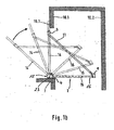
- Figur 1b
- verschiedene Positionen der verschwenkbaren Arbeitsbühne;
Figur 2- ein weiteres Ausführungsbeispiel der Arbeitsbühne mit einem Doppelgerüst, das am oberen Ende der Arbeitsbühne befestigt ist;
Figur 3+4- verschiedene Einrichtungen zur Verbindung der Streben der Arbeitsbühne.
- Figure la
- a schematic representation of a platform for elevator shafts or for attachment to wall openings of buildings;
- FIG. 1b
- different positions of the pivoting platform;
- FIG. 2
- a further embodiment of the work platform with a double frame, which is fixed to the upper end of the working platform;
- Figure 3 + 4
- various devices for connecting the struts of the platform.
In der zeichnung ist mit 1 eine Vorrichtung zum Aufnehmen und/oder zum Verstellen einer Arbeitsplattform 2 bereichnet, die entweder zwischen zwei gegenüberliegenden Wänden 10.1, 10.2 eines Aufzugrschachts oder auf einfache Weise in eine Maueröffnung einer vertikal verlaufenden Wand 10.1 im Bereich einer Türschwelle 7 eingesetzt und festgesetzt werden kann. Die Vorrichtung 1 zum Feststellen der Arbeitsplattform 2 weist einen Fuß auf, der als Stützteil 4 ausgebildet ist und im Ausführungsbeispiel ein Winkelstück darstellt. In vorteilhafter weise kann das Stützteil 4 bzw. das Winkelstück an einer Eckkante eines Bodens einer Wand 10.1 bzw. einer Türschwelle 7 aufgesetzt werden und auf diese weise die gesamte Vorrichtung 1 zum. Aufnehmen und/oder Verstellen der Arbeitsplattform 2 aufnehmen. An das stützteil bzw. an den Winkelträger 4 ist eine erste Halterung 12 fest angeschlossen.In the drawing, with 1 a device for receiving and / or adjusting a working
Die erste Halterung 12 besteht wie in
Seitlich von dem Querträger 16 kann im vertikalen Aufnahmeteil 12.3 das untere Ende einer vertikal ausgerichteten Strebe bzw. Vertikalstrebe 14 aufgenommen werden. Die Vertikalstrebe 14 kann ebenfalls durch den oben erwähnten Bolzen 23 arretiert werden. Die Vertikalstrebe 14 kann als einfaches Vierkantrohr oder als Teleskoprohr ausgebildet sein und somit kann die Länge der Vertikalstrebe 14 verändert und den unterschiedlichen Arbeitsbedingungen angepasst werden.Laterally from the
Die erste Halterung 12 ist, wie bereits erwähnt, mit dem Winkelstück 4 fest bzw. über nicht dargestellte Schraubenelemente lösbar verbunden. Im Ausführungsbeispiel ist in
Das Stützteil 4 ist an einer ersten Seite 6a der Arbeitsplattform 2 befestigt. An einer dem Stützteil 4 gegenüberliegenden zweiten Seite 6b der Arbeitsplattform 2 befindet sich eine zweite Halterung 9, die in
Die zweite Halterung 9 besteht wie in
An das Aufnahmeteil 26 schließt sich ein geneigt verlaufendes Aufnahmeteil 18 an, das im Querschnitt aus einem U-förmigen Profil besteht, in das das untere Ende der geneigt verlaufenden Zugstrebe 11 eingesetzt und über den Sicherungsbolzen 20 gesichert ist. In dem Aufnahmeteil 18 und/oder in der Zugstrebe 11 können mehrere nebeneinander angeordnete Bohrungen vorgesehen sein, so dass der sicherungsbolzen 20 in verschiedene Positionen eingesetzt und somit die Anschlussstelle der zugstrebe 11 verändert werden kann. Das andere bzw. obere Ende der Zugstrebe 11 ist ebenfalls in einem geneigt verlaufenden Aufnahmeteil 18.1 angeordnet und über den Sicherungsbolzen 21 arretiert. Die beiden Aufnahmeteile 18 und 18.1, die mit der Vertikalen bzw. Horizontalen einen winkel von 45° einschließen, können mit dem horizontale verlaufenden Aufnahmeteil 17 und dem vertikal verlaufenden Aufnahmeteil 26 auch so verbunden sein, dass sich die Winkellage des Aufnahmeteils 18.1 bzw. 18 gegenüber der Horizontalen verändern kann.To the receiving
Die beiden Balterungen 9 und 12 befinden sich beiderseits der Arbeitsbühne 2, die im Ausführungsbeispiel gemäß Figur 1a, 1b und 2 rechteckförmig ausgebildet ist. Im Ausführungsbeispiel gibt es zwei vertikalstreben 14, 33, an die die Zugstrebe 11 angeschlossen ist. Die Vertikalstreben 14, 33 sind mit Abstand zueinander angeordnete, wobei die Vertikalstrebe 33 im Bereich der zweiten Seite 6b an der Bodenplatte 15 vorgesehen ist. Zwischen den Vertikalstreben 14 und 33 befinden sich der horizontal verlaufende Querträgers 16 zur Aufnahme der Bodenplatte 15 und die Querstreben 29, 30 und 31 bzw. gemäß
Die Verbindungsvorrichtungen können mit je einer Halterung 5 ebenfalls auf die Vertikalstreben 14, 33 aufgesetzt werden. Die Verbindungsvorrichtungen 13.1, 13.2 dienen, wie bereits erwähnt und in
Die Querstreben 29 bis 31 und 34.2 bis 36 stellen einmal seitliche Begrenzungen der Arbeitsplattformen 2, 2' dar und dienen zur Sicherung der Arbeitsperson auf den Arbeitsplattformen 2, 2'. Ferner ist es jedoch auch möglich, dass die Querträger 16, 34 zur Aufnahme von Bodenplatten 15 dienen, die je nach den Arbeitsbedingungen auf unterschiedliche Höhen montiert werden können, um auf diese Weise dem. Baufortschritt nach oben hin zu folgen und der Bedienungsperson auf verschiedenen Ebenen eine oder mehrere Arbeitsplattformen 2, 2' zu bieten.The transverse struts 29 to 31 and 34.2 to 36 represent once lateral boundaries of the working
Im Ausführungsbeispiel ist gemäß
In vorteilhafter Weise sind die Vertikalstreben 14 und/oder 14.2 so ausgebildet, dass sie das gesamte Gewicht einer oder mehrerer Arbeitsplattformen 2 mit allen Einzelteilen aufnehmen können. Hierzu stützt sich die Vertikalstrebe 14, wie bereits erwähnt, mit ihrem unteren Ende gegen das Wandteil 10.1 ab und mit ihrem oberen Anlageteil 14.1 gegen die Innenseite 40 eines Türsturzes 19.1 einer Türöffnung 19. Der Türsturz 19.1 nimmt das gesamte Kippmoment einer Arbeitsplattform 2 auf. Die übrigen Teile der Arbeitsplattform 2 werden lediglich durch die beiden nebeneinanderliegenden Zugstreben 11 aufgefangen. Weitere Abstützelemente sind nicht erforderlich.Advantageously, the
Der Querträger 16 und die Querstreben 29 bis 31 und 34 bis 36 können ebenfalls längenveränderlich ausgebildet sein. Somit lässt sich beispielsweise der Arbeitsbereich der Arbeitsplattform 2 vergrößern oder die Arbeitsplattform 2 an eine in der Zeichnung nicht dargestellte Schachttiefe anpassen. The
- 11
- vorrichtungcontraption
- 22
- Arbeitsplattformworking platform
- 2'2 '
- Arbeitsplattformworking platform
- 33
- obere Halterungupper bracket
- 44
- Stützteil, winkwlträgerSupport member, winkwlträger
- 55
- Halterungbracket
- 6a6a
- erste Seite der Arbeitsplattformfirst page of the work platform
- 6b6b
- zweite Seite den Arbeitsplattformsecond side of the work platform
- 77
- Widerlager, TürschwelleAbutment, threshold
- 99
- zweite Halterungsecond bracket
- 10.110.1
- Wand eines AufzugsschachtsWall of a lift shaft
- 10.210.2
- Wand eines AufzugsschachtsWall of a lift shaft
- 1111
- Zugstrebetension strut
- 1212
- erste Halterung, Aufnalemeteilfirst holder, holding part
- 12.112.1
- U-förmiges AufnahmeteilU-shaped receiving part
- 12.212.2
- horizontales Aufnahmeteilhorizontal receiving part
- 12.312.3
- vertikales Aufnahmeteilvertical receiving part
- 13.113.1
- Verbindungsvorrichtungconnecting device
- 13.213.2
- Verbindungsvorrichtungconnecting device
- 13.313.3
- verbindungsvorrichtungconnecting device
- 13.413.4
- Verbindungsvorrichtungconnecting device
- 1414
- Vertikalstrebe, StrebeVertical strut, strut
- 14.114.1
- Vertikalstrebe, oberes AnlageteilVertical strut, upper part of the system
- 14.214.2
- Vertikalstrebevertical strut
- 1515
- Bodenplattebaseplate
- 1616
- Querträgercrossbeam
- 1717
- Aufnahmeteil, horizontalReceiving part, horizontal
- 1818
- Aufnahmeteilreceiving part
- 18.118.1
- Aufnahmeteilreceiving part
- 1919
- Türöffnungdoorway
- 19.119.1
- Türsturzlintel
- 2020
- Gelenkverbindung, SicherungsbolzenArticulated connection, safety bolt
- 2121
- Gelenkbolzen, SicherungsbolzenJoint bolt, safety bolt
- 2323
- Bolzen, sicherungselementBolt, securing element
- 2424
- Bohrungdrilling
- 2626
- Aufnahmeteil, vertikalReceiving part, vertical
- 2929
- Querstrebecrossmember
- 3030
- Querstrebecrossmember
- 3131
- Querstrebecrossmember
- 3333
- Vertikalstrebe, StrebeVertical strut, strut
- 3434
- Querträgercrossbeam
- 34.234.2
- Querstrebecrossmember
- 3535
- Querstrebecrossmember
- 3636
- Querstrebecrossmember
- 3737
- hintere Streberear strut
- 3838
- Leiterladder
- 3939
- Bodenplattenfloor tiles
- 4040
- Innenseiteinside
Claims (18)
- Working stage having the following features:1.1. it comprises a device (1) for receiving and/or adjusting a working platform (2),1.2 the device (1) of the working platform (2) comprises a support part (4) to which the working platform (2) is connected by means of a first holding device (12), and which supports the entire device (1),1.3 the working platform (2) can be supported, against an abutment (7) or a wall (10.1), in the area of a first side (6a), by means of the first holding device (12), 1.3a. the working platform (2) is connected by means of the first holding device (12) with a vertical strut (14) which is arranged substantially perpendicular to a cross member (16) of the working platform (2),1.4 the working platform (2) has a second holding device (9), on a second side (6b) opposite the first side (6a), by means of which the working platform (2) can be received, 1.5 the second holding device (9) is connected to a rigid tension strut (11),1.6 the tension strut (11) is firmly connected with its one end to the working platform (2) and with its other end to the vertical strut (14),1.7. at least one additional vertical strut (33), which serves to receive one or more cross struts (30), can be mounted on the working platform (2) parallel to and at a distance from the first vertical strut (14),characterized in that
the holding device (12) comprises a U-shaped receptacle portion (12.1) having a bore (24) into which a horizontally extending receptacle portion (12.2) and a vertically extending receptacle portion (12.3), each having a bore (24), are inserted, wherein the receptacle portions (12.2,12.3) are connected to one another in the bores (24) by means of a bolt (23), and
the vertical strut (14) and the cross beam (16) of the working platform (2) connected to the vertical strut (14) by means of the tension strut (11) are, at the same time, swivelably supported about a joint bolt (23) on the support part (4) with the aid of the first holding device (12). - The device (1) according to Claim 1, characterized in that the cross member (16) and the vertical strut (14) are inserted into the first holding device (12) and are each secured with the aid of the bolt (23).
- The device (1) according to Claim 2, characterized in that the working platform (2) is formed by the cross member (16) and a base plate (15) resting on the cross member (16), wherein the cross member (16) is connected to the tension strut (11) by means of the second holding device (9).
- The device (1) according to Claim 3, characterized in that the tension strut (11) is articulated to the second holding device (9) with the aid of an articulated connection (20).
- The device (1) according to Claim 4, characterized in that the first vertical strut (14) is connected to the second vertical strut (33) by means of three substantially horizontally arranged cross struts (29, 30, 31).
- The device (1) according to Claim 5, characterized in that above the working platform (2) a second working platform (2') having a base plate (39) is provided, which is connected via a cross member (34) with the first vertical strut (14) and with the second vertical strut (33).
- The device (1) according to Claim 6, characterized in that a vertical strut (14.2) and a vertically extending rear strut (37) are assigned to the second working platform (2'), wherein the vertical strut (14.2) is fixed to the cross member (34) and the rear strut (37) is inserted in the vertical strut (33).
- The device (1) according to Claim 7, characterized in that the vertical strut (14.2) and the rear strut (37) are connected by means of three substantially horizontally extending cross struts (34.2, 35, 36).
- The device (1) according to Claim 8, characterized in that the working platform (2') has an opening as a way through and for a ladder (38).
- The device (1) according to Claim 1, characterized in that the first vertical strut (14) receives and/or supports the entire working platform (2).
- The device (1) according to Claim 1, characterized in that the support part (4) is formed as an angle portion which can be supported against the corner portion of a wall (10.1) or a door sill (7).
- The device (1) according to any one of Claims 1 or 10, characterized in that the first holding device (12) has a vertically extending receptacle portion (12.3) for receiving the vertical strut (14) with a positive fit and/or a second horizontally extending receptacle portion (12.2) for receiving the horizontally extending cross member (16), with which the base plate (15) can be connected, and has a U-shaped receptacle portion (12.1) for receiving the vertical and the horizontal receptacle portion (12.2, 12.3).
- The device (1) according to Claim 12, characterized in that at least the horizontal receptacle portion (12.2) and the vertical receptacle portion (12.3) form a one-piece component.
- The device (1) according to Claim 10, characterized in that the U-shaped receptacle portion (12.1) can be firmly connected with the support part (4) which is formed as an angle portion.
- The device (1) according to any one of Claims 1 or 10, characterized in that the tension strut (11) is connected by means of an upper holding device (3) in the area of the upper portion of the vertical strut (14) thereto.
- The device (1) according to any one of Claims 1 or 10, characterized in that at least one connecting device (13.1, 13.2, 13.3) each is provided on the holding devices (12, 9) and/or on the vertical struts (14, 33), which connecting devices serve to receive horizontally extending or approximately horizontally extending cross struts (30) or additional cross struts (30) extending in an inclined manner and/or base plates.
- The device (1) according to Claim 16, characterized in that the connecting devices (13.1, 13.2) are adjustably supported on the vertical struts (14, 33) and can be fixed by means of securing elements or bolts (23) to the vertical struts (14, 33).
- The device (1) according to any one of Claims 1 or 10, characterized in that the working platform (2) or the base plate (15) is sufficiently wide and/or long that it can be swiveled through the door opening (19).
Applications Claiming Priority (1)
| Application Number | Priority Date | Filing Date | Title |
|---|---|---|---|
| PCT/EP2002/007764 WO2004007869A1 (en) | 2002-07-12 | 2002-07-12 | Working gantry |
Publications (2)
| Publication Number | Publication Date |
|---|---|
| EP1527242A1 EP1527242A1 (en) | 2005-05-04 |
| EP1527242B1 true EP1527242B1 (en) | 2014-04-30 |
Family
ID=30011044
Family Applications (1)
| Application Number | Title | Priority Date | Filing Date |
|---|---|---|---|
| EP02754875.9A Expired - Lifetime EP1527242B1 (en) | 2002-07-12 | 2002-07-12 | Working gantry |
Country Status (8)
| Country | Link |
|---|---|
| US (1) | US7108100B2 (en) |
| EP (1) | EP1527242B1 (en) |
| JP (1) | JP4260106B2 (en) |
| CN (1) | CN100537973C (en) |
| AU (1) | AU2002321212A1 (en) |
| BR (1) | BR0215815A (en) |
| HK (1) | HK1076137A1 (en) |
| WO (1) | WO2004007869A1 (en) |
Cited By (2)
| Publication number | Priority date | Publication date | Assignee | Title |
|---|---|---|---|---|
| US11518651B2 (en) | 2017-06-02 | 2022-12-06 | Inventio Ag | Additional platform for a working platform |
| US11598106B2 (en) | 2017-06-02 | 2023-03-07 | Inventio Ag | Platform for assembling elevator equipment |
Families Citing this family (24)
| Publication number | Priority date | Publication date | Assignee | Title |
|---|---|---|---|---|
| WO2005007551A1 (en) * | 2003-07-22 | 2005-01-27 | Mitsubishi Denki Kabushiki Kaisha | Working scaffold system of elevator |
| EP1531210A1 (en) * | 2003-11-13 | 2005-05-18 | Inventio Ag | Working platform for elevator shafts for the installation of elevator components and method for installing an elevator shaft working platform |
| GB2417944B (en) * | 2004-09-08 | 2008-01-30 | Aire Valley Metal Products Ltd | Lift shaft work platform |
| EP1910208A1 (en) * | 2005-08-04 | 2008-04-16 | Otis Elevator Company | Support bridge for elevator installation and the system thereof |
| GB2452269B (en) * | 2007-08-29 | 2012-08-01 | Aire Valley Metal Products Ltd | Lift shaft work platform |
| US8646224B2 (en) * | 2008-09-17 | 2014-02-11 | Wurtec Elevator Products & Services | Construction apparatus |
| SG186043A1 (en) * | 2008-11-12 | 2012-12-28 | Arbeit Sicher Pte Ltd | Mobile cantilever platforms and methods of installation thereof |
| US8141683B1 (en) | 2009-04-30 | 2012-03-27 | Wurtec Elevator Products & Services | Expandable platform |
| US8646576B2 (en) | 2009-07-30 | 2014-02-11 | Wurtec Elevator Products & Services | Foldable hoistway work deck |
| CN102108783A (en) * | 2010-12-31 | 2011-06-29 | 青建集团股份公司 | Operation platform in control tower overhanging structure and construction method thereof |
| JP5844654B2 (en) * | 2012-02-15 | 2016-01-20 | 大和ハウス工業株式会社 | Window scaffolding |
| CN103580592A (en) * | 2012-08-09 | 2014-02-12 | 富昱能源科技(昆山)有限公司 | Support structure |
| CN104477736A (en) * | 2012-10-12 | 2015-04-01 | 广州广日电梯工程有限公司 | Shaft elevator installation method |
| US10024488B2 (en) | 2014-10-06 | 2018-07-17 | Wurtec, Incorporated | Three-beam construction apparatus |
| CN104631808B (en) * | 2015-01-22 | 2017-06-13 | 杭州李春建设有限公司 | Portable job platform |
| JP6419051B2 (en) * | 2015-10-01 | 2018-11-07 | 三菱電機株式会社 | Elevator installation work scaffolding |
| US10464783B2 (en) | 2017-10-17 | 2019-11-05 | Germain Depot | Elevator shaft access safety device and method of using the same |
| US10815729B2 (en) | 2018-01-04 | 2020-10-27 | thyssenkrupp Elevator Innovation & Operations GmbH | Ladder landing support apparatus |
| CN110424710A (en) * | 2019-07-31 | 2019-11-08 | 云南省建设投资控股集团有限公司 | Elevator tool-type all steel operation platform construction |
| US11939782B2 (en) | 2020-01-21 | 2024-03-26 | Aaa Royal Construction Llc | Wall-mountable perch |
| CN111498760B (en) * | 2020-05-28 | 2024-08-30 | 无锡瑞吉德机械有限公司 | Large-load elevator installation platform capable of stepless telescoping |
| KR102373661B1 (en) * | 2020-10-20 | 2022-03-15 | 한국산업안전보건공단 | Scaffolding device for maintaining of elevator |
| EP4267507A1 (en) * | 2020-12-22 | 2023-11-01 | KONE Corporation | Construction arrangement of an elevator and method |
| KR102536340B1 (en) * | 2021-06-24 | 2023-05-26 | 한국산업안전보건공단 | Scaffolding system for installing elevator |
Family Cites Families (23)
| Publication number | Priority date | Publication date | Assignee | Title |
|---|---|---|---|---|
| US401410A (en) * | 1889-04-16 | Safety-scaffold | ||
| DE803075C (en) * | 1948-10-12 | 1951-02-26 | Friedrich Koehler | Window workhorse |
| US2888225A (en) * | 1954-11-03 | 1959-05-26 | Earl J Cowell | Combination roof and scaffold bracket |
| US3605944A (en) * | 1969-12-12 | 1971-09-20 | Wendell Cleghorn | Adjustable scaffold and bracket |
| US3894634A (en) * | 1971-03-19 | 1975-07-15 | Unex Conveying Systems Inc | Display and delivery stand |
| US4029173A (en) * | 1974-12-30 | 1977-06-14 | Hidenori Wakabayashi | Foldable scaffold devices |
| US4280243A (en) * | 1979-08-06 | 1981-07-28 | Richard Durrant | Bulk loading facility having a drop way |
| JPH0829905B2 (en) * | 1988-03-01 | 1996-03-27 | 株式会社日立ビルシステムサービス | Hoistway scaffolding equipment |
| FR2641018A1 (en) | 1988-12-22 | 1990-06-29 | Otis Elevator Co | Building-site scaffolding to be climbed in particular in elevator hoppers |
| US4979725A (en) * | 1989-04-11 | 1990-12-25 | Michael J. Quigley | Roof safety barrier supporting frame |
| US5269394A (en) * | 1992-05-20 | 1993-12-14 | Haroldson Sr Acey A | Universal bracket apparatus for attaching toe boards to scaffolds |
| US5379859A (en) * | 1993-06-21 | 1995-01-10 | Pigman; Steven O. | Adjustable roof scaffold support assembly |
| US5524727A (en) * | 1994-10-13 | 1996-06-11 | Yennie, Jr.; Roland | Construction wall bracket |
| US5896944A (en) * | 1995-04-24 | 1999-04-27 | Mcmillian; James D. | Adjustable rail barricade for working on a roof |
| US6039150A (en) * | 1995-05-03 | 2000-03-21 | Palmer; Theodore R. | Building guard rail scaffold assembly |
| US5638917A (en) * | 1995-11-27 | 1997-06-17 | Vennen; Dennis L. | Scaffold bracket for roof structure installation |
| US5778999A (en) * | 1997-03-10 | 1998-07-14 | Nealeigh; Dustin L. | Scaffold extension and enclosure system |
| US6003630A (en) * | 1997-06-24 | 1999-12-21 | Construction Systems, Inc. | Unilateral scaffold system |
| JP2000328777A (en) * | 1999-05-13 | 2000-11-28 | Otis Elevator Co | Elevator installing scaffold structure |
| DE19928574C2 (en) | 1999-06-23 | 2001-11-15 | Stingl Montage Und Befestigung | Working platform |
| US6264001B1 (en) * | 2000-01-04 | 2001-07-24 | Robert Herschbach | Scaffolding hanger |
| CA2313513C (en) * | 2000-07-06 | 2008-10-14 | Michel Philippe | Scaffolding |
| US6494291B2 (en) * | 2001-04-27 | 2002-12-17 | Tatsuo Ono | Foldable scaffold device |
-
2002
- 2002-07-12 JP JP2004520353A patent/JP4260106B2/en not_active Expired - Lifetime
- 2002-07-12 WO PCT/EP2002/007764 patent/WO2004007869A1/en active Application Filing
- 2002-07-12 BR BR0215815-9A patent/BR0215815A/en not_active Application Discontinuation
- 2002-07-12 CN CNB028292774A patent/CN100537973C/en not_active Expired - Fee Related
- 2002-07-12 AU AU2002321212A patent/AU2002321212A1/en not_active Abandoned
- 2002-07-12 EP EP02754875.9A patent/EP1527242B1/en not_active Expired - Lifetime
-
2005
- 2005-01-12 US US11/034,306 patent/US7108100B2/en not_active Expired - Lifetime
- 2005-09-20 HK HK05108218.4A patent/HK1076137A1/en not_active IP Right Cessation
Cited By (2)
| Publication number | Priority date | Publication date | Assignee | Title |
|---|---|---|---|---|
| US11518651B2 (en) | 2017-06-02 | 2022-12-06 | Inventio Ag | Additional platform for a working platform |
| US11598106B2 (en) | 2017-06-02 | 2023-03-07 | Inventio Ag | Platform for assembling elevator equipment |
Also Published As
| Publication number | Publication date |
|---|---|
| EP1527242A1 (en) | 2005-05-04 |
| CN1639434A (en) | 2005-07-13 |
| JP4260106B2 (en) | 2009-04-30 |
| BR0215815A (en) | 2005-06-07 |
| US20050139421A1 (en) | 2005-06-30 |
| WO2004007869A1 (en) | 2004-01-22 |
| JP2005536668A (en) | 2005-12-02 |
| CN100537973C (en) | 2009-09-09 |
| AU2002321212A1 (en) | 2004-02-02 |
| HK1076137A1 (en) | 2006-01-06 |
| US7108100B2 (en) | 2006-09-19 |
Similar Documents
| Publication | Publication Date | Title |
|---|---|---|
| EP1527242B1 (en) | Working gantry | |
| DE69803731T2 (en) | METHOD AND DEVICE FOR INSTALLING AN ELEVATOR | |
| DE10344201A1 (en) | Solar module fixing e.g. for roof-mounted solar installation, with respective solar module frame enclosing each solar module | |
| EP0611726B1 (en) | Lift for the installation and the removal of vehicle parts | |
| DE60317171T2 (en) | Adjustable modular safety system for scaffolding | |
| DE202010005250U1 (en) | Mounting system for solar modules | |
| AT523944B1 (en) | railing module | |
| DE19928574C2 (en) | Working platform | |
| DE10243356A1 (en) | Method for fitting safety railing to demountable scaffold has vertical supports clamped parallel to the scaffold vertical supports and with clamping fittings to the plank supports | |
| EP3656918B1 (en) | Railway barrier device for mobile track protection system | |
| DE3401873A1 (en) | Device for fastening a scaffold element in a suspended manner | |
| AT507899B1 (en) | HANGING FRAME | |
| EP1589627A1 (en) | Device vor lifting and fastening busbars | |
| EP0881341A1 (en) | Attachment for suspended scaffolds | |
| DE69016041T2 (en) | HANGING SCAFFOLDING. | |
| EP1371788B1 (en) | Mounting frame for sanitary apparatuses | |
| DE10033646C1 (en) | Installation frame for carrier construction in building elevator shaft pivoted between stowed position and working position in which it extends across elevator shaft | |
| DE69634898T2 (en) | safety device | |
| DE69916815T2 (en) | Frame for floor components of a scaffold | |
| EP3560882B1 (en) | Transfer for an elevator | |
| DE102015206072B4 (en) | Railing and scaffolding | |
| EP2246503A2 (en) | Scaffold hanging from a roof | |
| DE19649327C2 (en) | Scaffolding | |
| EP0903261B1 (en) | Mounting device for a loading tailgate | |
| DE102023200592A1 (en) | House wall anchoring for fall protection |
Legal Events
| Date | Code | Title | Description |
|---|---|---|---|
| PUAI | Public reference made under article 153(3) epc to a published international application that has entered the european phase |
Free format text: ORIGINAL CODE: 0009012 |
|
| 17P | Request for examination filed |
Effective date: 20050128 |
|
| AK | Designated contracting states |
Kind code of ref document: A1 Designated state(s): AT BE BG CH CY CZ DE DK EE ES FI FR GB GR IE IT LI LU MC NL PT SE SK TR |
|
| AX | Request for extension of the european patent |
Extension state: AL LT LV MK RO SI |
|
| DAX | Request for extension of the european patent (deleted) | ||
| 17Q | First examination report despatched |
Effective date: 20081016 |
|
| REG | Reference to a national code |
Ref country code: DE Ref legal event code: R079 Ref document number: 50215919 Country of ref document: DE Free format text: PREVIOUS MAIN CLASS: E04G0003000000 Ipc: E04G0001360000 |
|
| RIC1 | Information provided on ipc code assigned before grant |
Ipc: E04G 3/18 20060101ALI20131018BHEP Ipc: E04G 1/36 20060101AFI20131018BHEP |
|
| GRAP | Despatch of communication of intention to grant a patent |
Free format text: ORIGINAL CODE: EPIDOSNIGR1 |
|
| INTG | Intention to grant announced |
Effective date: 20131206 |
|
| GRAS | Grant fee paid |
Free format text: ORIGINAL CODE: EPIDOSNIGR3 |
|
| GRAA | (expected) grant |
Free format text: ORIGINAL CODE: 0009210 |
|
| AK | Designated contracting states |
Kind code of ref document: B1 Designated state(s): AT BE BG CH CY CZ DE DK EE ES FI FR GB GR IE IT LI LU MC NL PT SE SK TR |
|
| REG | Reference to a national code |
Ref country code: GB Ref legal event code: FG4D Free format text: NOT ENGLISH Ref country code: CH Ref legal event code: EP |
|
| REG | Reference to a national code |
Ref country code: AT Ref legal event code: REF Ref document number: 665279 Country of ref document: AT Kind code of ref document: T Effective date: 20140515 |
|
| REG | Reference to a national code |
Ref country code: IE Ref legal event code: FG4D Free format text: LANGUAGE OF EP DOCUMENT: GERMAN |
|
| REG | Reference to a national code |
Ref country code: DE Ref legal event code: R096 Ref document number: 50215919 Country of ref document: DE Effective date: 20140612 |
|
| REG | Reference to a national code |
Ref country code: NL Ref legal event code: VDEP Effective date: 20140430 |
|
| PG25 | Lapsed in a contracting state [announced via postgrant information from national office to epo] |
Ref country code: CY Free format text: LAPSE BECAUSE OF FAILURE TO SUBMIT A TRANSLATION OF THE DESCRIPTION OR TO PAY THE FEE WITHIN THE PRESCRIBED TIME-LIMIT Effective date: 20140430 Ref country code: FI Free format text: LAPSE BECAUSE OF FAILURE TO SUBMIT A TRANSLATION OF THE DESCRIPTION OR TO PAY THE FEE WITHIN THE PRESCRIBED TIME-LIMIT Effective date: 20140430 Ref country code: GR Free format text: LAPSE BECAUSE OF FAILURE TO SUBMIT A TRANSLATION OF THE DESCRIPTION OR TO PAY THE FEE WITHIN THE PRESCRIBED TIME-LIMIT Effective date: 20140731 Ref country code: NL Free format text: LAPSE BECAUSE OF FAILURE TO SUBMIT A TRANSLATION OF THE DESCRIPTION OR TO PAY THE FEE WITHIN THE PRESCRIBED TIME-LIMIT Effective date: 20140430 Ref country code: BG Free format text: LAPSE BECAUSE OF FAILURE TO SUBMIT A TRANSLATION OF THE DESCRIPTION OR TO PAY THE FEE WITHIN THE PRESCRIBED TIME-LIMIT Effective date: 20140730 |
|
| PG25 | Lapsed in a contracting state [announced via postgrant information from national office to epo] |
Ref country code: ES Free format text: LAPSE BECAUSE OF FAILURE TO SUBMIT A TRANSLATION OF THE DESCRIPTION OR TO PAY THE FEE WITHIN THE PRESCRIBED TIME-LIMIT Effective date: 20140430 Ref country code: SE Free format text: LAPSE BECAUSE OF FAILURE TO SUBMIT A TRANSLATION OF THE DESCRIPTION OR TO PAY THE FEE WITHIN THE PRESCRIBED TIME-LIMIT Effective date: 20140430 |
|
| PG25 | Lapsed in a contracting state [announced via postgrant information from national office to epo] |
Ref country code: PT Free format text: LAPSE BECAUSE OF FAILURE TO SUBMIT A TRANSLATION OF THE DESCRIPTION OR TO PAY THE FEE WITHIN THE PRESCRIBED TIME-LIMIT Effective date: 20140901 |
|
| PG25 | Lapsed in a contracting state [announced via postgrant information from national office to epo] |
Ref country code: SK Free format text: LAPSE BECAUSE OF FAILURE TO SUBMIT A TRANSLATION OF THE DESCRIPTION OR TO PAY THE FEE WITHIN THE PRESCRIBED TIME-LIMIT Effective date: 20140430 Ref country code: CZ Free format text: LAPSE BECAUSE OF FAILURE TO SUBMIT A TRANSLATION OF THE DESCRIPTION OR TO PAY THE FEE WITHIN THE PRESCRIBED TIME-LIMIT Effective date: 20140430 Ref country code: EE Free format text: LAPSE BECAUSE OF FAILURE TO SUBMIT A TRANSLATION OF THE DESCRIPTION OR TO PAY THE FEE WITHIN THE PRESCRIBED TIME-LIMIT Effective date: 20140430 Ref country code: DK Free format text: LAPSE BECAUSE OF FAILURE TO SUBMIT A TRANSLATION OF THE DESCRIPTION OR TO PAY THE FEE WITHIN THE PRESCRIBED TIME-LIMIT Effective date: 20140430 |
|
| REG | Reference to a national code |
Ref country code: DE Ref legal event code: R097 Ref document number: 50215919 Country of ref document: DE |
|
| PG25 | Lapsed in a contracting state [announced via postgrant information from national office to epo] |
Ref country code: LU Free format text: LAPSE BECAUSE OF FAILURE TO SUBMIT A TRANSLATION OF THE DESCRIPTION OR TO PAY THE FEE WITHIN THE PRESCRIBED TIME-LIMIT Effective date: 20140712 |
|
| REG | Reference to a national code |
Ref country code: CH Ref legal event code: PL |
|
| PLBE | No opposition filed within time limit |
Free format text: ORIGINAL CODE: 0009261 |
|
| STAA | Information on the status of an ep patent application or granted ep patent |
Free format text: STATUS: NO OPPOSITION FILED WITHIN TIME LIMIT |
|
| GBPC | Gb: european patent ceased through non-payment of renewal fee |
Effective date: 20140730 |
|
| PG25 | Lapsed in a contracting state [announced via postgrant information from national office to epo] |
Ref country code: IT Free format text: LAPSE BECAUSE OF FAILURE TO SUBMIT A TRANSLATION OF THE DESCRIPTION OR TO PAY THE FEE WITHIN THE PRESCRIBED TIME-LIMIT Effective date: 20140430 |
|
| 26N | No opposition filed |
Effective date: 20150202 |
|
| REG | Reference to a national code |
Ref country code: IE Ref legal event code: MM4A |
|
| PG25 | Lapsed in a contracting state [announced via postgrant information from national office to epo] |
Ref country code: LI Free format text: LAPSE BECAUSE OF NON-PAYMENT OF DUE FEES Effective date: 20140731 Ref country code: CH Free format text: LAPSE BECAUSE OF NON-PAYMENT OF DUE FEES Effective date: 20140731 |
|
| REG | Reference to a national code |
Ref country code: DE Ref legal event code: R097 Ref document number: 50215919 Country of ref document: DE Effective date: 20150202 |
|
| PG25 | Lapsed in a contracting state [announced via postgrant information from national office to epo] |
Ref country code: GB Free format text: LAPSE BECAUSE OF NON-PAYMENT OF DUE FEES Effective date: 20140730 |
|
| PG25 | Lapsed in a contracting state [announced via postgrant information from national office to epo] |
Ref country code: IE Free format text: LAPSE BECAUSE OF NON-PAYMENT OF DUE FEES Effective date: 20140712 |
|
| REG | Reference to a national code |
Ref country code: AT Ref legal event code: MM01 Ref document number: 665279 Country of ref document: AT Kind code of ref document: T Effective date: 20140712 |
|
| PG25 | Lapsed in a contracting state [announced via postgrant information from national office to epo] |
Ref country code: AT Free format text: LAPSE BECAUSE OF NON-PAYMENT OF DUE FEES Effective date: 20140712 |
|
| PG25 | Lapsed in a contracting state [announced via postgrant information from national office to epo] |
Ref country code: MC Free format text: LAPSE BECAUSE OF FAILURE TO SUBMIT A TRANSLATION OF THE DESCRIPTION OR TO PAY THE FEE WITHIN THE PRESCRIBED TIME-LIMIT Effective date: 20140430 |
|
| REG | Reference to a national code |
Ref country code: FR Ref legal event code: PLFP Year of fee payment: 15 |
|
| PG25 | Lapsed in a contracting state [announced via postgrant information from national office to epo] |
Ref country code: BE Free format text: LAPSE BECAUSE OF FAILURE TO SUBMIT A TRANSLATION OF THE DESCRIPTION OR TO PAY THE FEE WITHIN THE PRESCRIBED TIME-LIMIT Effective date: 20140731 Ref country code: TR Free format text: LAPSE BECAUSE OF FAILURE TO SUBMIT A TRANSLATION OF THE DESCRIPTION OR TO PAY THE FEE WITHIN THE PRESCRIBED TIME-LIMIT Effective date: 20140430 |
|
| REG | Reference to a national code |
Ref country code: FR Ref legal event code: PLFP Year of fee payment: 16 |
|
| REG | Reference to a national code |
Ref country code: FR Ref legal event code: PLFP Year of fee payment: 17 |
|
| PGFP | Annual fee paid to national office [announced via postgrant information from national office to epo] |
Ref country code: FR Payment date: 20200721 Year of fee payment: 19 Ref country code: DE Payment date: 20200721 Year of fee payment: 19 |
|
| REG | Reference to a national code |
Ref country code: DE Ref legal event code: R119 Ref document number: 50215919 Country of ref document: DE |
|
| PG25 | Lapsed in a contracting state [announced via postgrant information from national office to epo] |
Ref country code: DE Free format text: LAPSE BECAUSE OF NON-PAYMENT OF DUE FEES Effective date: 20220201 |
|
| PG25 | Lapsed in a contracting state [announced via postgrant information from national office to epo] |
Ref country code: FR Free format text: LAPSE BECAUSE OF NON-PAYMENT OF DUE FEES Effective date: 20210731 |