EP1526939B1 - Vorrichtung zum entleeren von schmelze aus einem behälter - Google Patents
Vorrichtung zum entleeren von schmelze aus einem behälter Download PDFInfo
- Publication number
- EP1526939B1 EP1526939B1 EP03763724A EP03763724A EP1526939B1 EP 1526939 B1 EP1526939 B1 EP 1526939B1 EP 03763724 A EP03763724 A EP 03763724A EP 03763724 A EP03763724 A EP 03763724A EP 1526939 B1 EP1526939 B1 EP 1526939B1
- Authority
- EP
- European Patent Office
- Prior art keywords
- outlet sleeve
- container
- nozzle
- ring shaped
- blade
- Prior art date
- Legal status (The legal status is an assumption and is not a legal conclusion. Google has not performed a legal analysis and makes no representation as to the accuracy of the status listed.)
- Expired - Lifetime
Links
- 239000002184 metal Substances 0.000 title claims abstract description 27
- 229910052751 metal Inorganic materials 0.000 title claims abstract description 27
- 238000007599 discharging Methods 0.000 title claims abstract description 18
- 239000011819 refractory material Substances 0.000 claims abstract description 8
- 239000004576 sand Substances 0.000 claims abstract description 7
- 230000008878 coupling Effects 0.000 claims description 10
- 238000010168 coupling process Methods 0.000 claims description 10
- 238000005859 coupling reaction Methods 0.000 claims description 10
- 238000007789 sealing Methods 0.000 claims description 4
- 238000009826 distribution Methods 0.000 claims description 3
- 239000011261 inert gas Substances 0.000 abstract description 2
- 239000007789 gas Substances 0.000 description 8
- XKRFYHLGVUSROY-UHFFFAOYSA-N Argon Chemical compound [Ar] XKRFYHLGVUSROY-UHFFFAOYSA-N 0.000 description 4
- 229910000831 Steel Inorganic materials 0.000 description 4
- 210000003141 lower extremity Anatomy 0.000 description 4
- 239000010959 steel Substances 0.000 description 4
- QVGXLLKOCUKJST-UHFFFAOYSA-N atomic oxygen Chemical compound [O] QVGXLLKOCUKJST-UHFFFAOYSA-N 0.000 description 3
- 238000005266 casting Methods 0.000 description 3
- 238000009749 continuous casting Methods 0.000 description 3
- 239000001301 oxygen Substances 0.000 description 3
- 229910052760 oxygen Inorganic materials 0.000 description 3
- IJGRMHOSHXDMSA-UHFFFAOYSA-N Atomic nitrogen Chemical compound N#N IJGRMHOSHXDMSA-UHFFFAOYSA-N 0.000 description 2
- XEEYBQQBJWHFJM-UHFFFAOYSA-N Iron Chemical compound [Fe] XEEYBQQBJWHFJM-UHFFFAOYSA-N 0.000 description 2
- 229910052786 argon Inorganic materials 0.000 description 2
- 239000012467 final product Substances 0.000 description 2
- 238000004519 manufacturing process Methods 0.000 description 2
- 239000000047 product Substances 0.000 description 2
- 210000001364 upper extremity Anatomy 0.000 description 2
- 241001131688 Coracias garrulus Species 0.000 description 1
- 230000015572 biosynthetic process Effects 0.000 description 1
- 230000001010 compromised effect Effects 0.000 description 1
- 238000011109 contamination Methods 0.000 description 1
- 238000005260 corrosion Methods 0.000 description 1
- 230000007797 corrosion Effects 0.000 description 1
- 230000009977 dual effect Effects 0.000 description 1
- 238000005516 engineering process Methods 0.000 description 1
- 229910052742 iron Inorganic materials 0.000 description 1
- 238000005304 joining Methods 0.000 description 1
- 230000002045 lasting effect Effects 0.000 description 1
- 239000000463 material Substances 0.000 description 1
- 239000000155 melt Substances 0.000 description 1
- 238000000034 method Methods 0.000 description 1
- 239000000203 mixture Substances 0.000 description 1
- 229910052757 nitrogen Inorganic materials 0.000 description 1
- 239000002244 precipitate Substances 0.000 description 1
- 230000001681 protective effect Effects 0.000 description 1
- 230000001105 regulatory effect Effects 0.000 description 1
- 125000006850 spacer group Chemical group 0.000 description 1
- 238000006467 substitution reaction Methods 0.000 description 1
Images

Classifications
-
- B—PERFORMING OPERATIONS; TRANSPORTING
- B22—CASTING; POWDER METALLURGY
- B22D—CASTING OF METALS; CASTING OF OTHER SUBSTANCES BY THE SAME PROCESSES OR DEVICES
- B22D37/00—Controlling or regulating the pouring of molten metal from a casting melt-holding vessel
- B22D37/005—Shielding the molten metal stream
-
- B—PERFORMING OPERATIONS; TRANSPORTING
- B22—CASTING; POWDER METALLURGY
- B22D—CASTING OF METALS; CASTING OF OTHER SUBSTANCES BY THE SAME PROCESSES OR DEVICES
- B22D41/00—Casting melt-holding vessels, e.g. ladles, tundishes, cups or the like
- B22D41/50—Pouring-nozzles
- B22D41/502—Connection arrangements; Sealing means therefor
Definitions
- the invention refers to a device for discharging molten metal from one container to another, from example from a ladle to a tundish or from a tundish to an under tundish for feeding a continuous casting line.
- the molten metal which originates for example from an electric furnace, or from a converter, is subjected to a series of pouring passages between containers, prior, to being cast in the ingot mould to form ingots, slabs, bars, strips and others.
- a typical example is given by the application of the technology of continuous strip casting in which the steel emerging from the production oven is collected in a ladle, from which it is unloaded into one or more tundishes, each of which feeds one or more melts above two cooled, counter rotating casting rolls, which form the ingot mould in which the metal solidifies and emerges in the form of finished product, for example a strip, a bar or otherwise.
- the tundish and the ingot mould can also be envisaged an under tundish, from which the molten metal passes into the ingot mould. It is known that the quality of the final product, and also the execution of the process itself can be compromised by the contact of air with the molten metal.
- the oxygen of the air can combine with elements dissolved in the steel forming inclusions, which deteriorate the quality of the steel, as also with dissolved oxygen itself.
- the oxygen combined with the iron can produce scale which deposits on the rolls, locally altering, amongst others, the heat exchange, with serious consequences for the final product.
- Nitrogen can also cause the formation of precipitates which compromise the quality of the product
- a protective atmosphere In the containers into which the molten metal must pass there is generally maintained a protective atmosphere, generally through the feeding of an inert gas, for example argon.
- an inert gas for example argon.
- Discharging devices in the known art are not easy to operate and require delicate operations to allow the approaching of two containers for joining.
- a further aim is that of providing a discharging device which allows a rapid, reliable and lasting coupling of the two containers, in the presence of molten metal at high temperature and which in addition is not is not prone to the impacts which occur during coupling of the containers.
- said outlet sleeve is placed with its vertical axis and penetrates into the lower container with its lower extremity, through an appropriately made hole in the cover of the latter.
- the sheath can be advantageously cylindrical, as with the blade, and be coaxial with the outlet sleeve, and be welded to the lower container, around said opening.
- said means for realising a gas seal are sand joints.
- the blade is preferably welded to the base of the upper container.
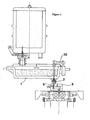
- a preferred embodiment of a discharging device which connects the base 1 of a tundish to an under tundish 2 or also of a ladle with a tundish.
- the cylindrical metal sheath 3, is welded to a plate 4 integral with the under tundish 2.
- the outlet sleeve 5 through the hole crosses the plate 4 and the upper walls 7 of the under tundish 2.
- the outlet sleeve 5 has a ring shaped protrusion 8 around its upper extremity.
- On the protrusion 8 act the means for pushing the outlet sleeve upwards and holding it vertically, comprising a helical spring 9, or equivalent elastic means, a metallic beaker 10, having intemally a metallic ring shaped support 11 which holds a ring 12 of refractory material into which the nozzle 5 is inserted.
- the spring 9 reacting against the plate 4 acts on the beaker 10, pushing the latter upwards and thus also the nozzle 5.
- a structure for centring the spring 9 and the beaker 10 can be envisaged.
- it is represented by a metal cylinder 13, surrounded by the spring 9, and around which runs the beaker 10.
- a tube 14 of refractory material is fixed to it with a spacer of refractory material adequate 24, for the protection of the spring 9 and the cylinder 13 from heat.
- the outlet sleeve 5 can run in the tube 14, pushed by the spring 9.
- spring 9 and cylinder 13 are coaxial to the outlet sleeve 5.
- the beaker 10 can run on the cylinder 13.
- the blade 15, Fixed to the plate 16, making part of the base 1 of the tundish, is cylindrical and is of shape and size such that its lower edge can penetrate into the ring shaped tank 17, filled with sand 26 or other appropriate material, said tank surrounding the upper edge of the sheath 3, thus realising a sand joint for the sealing of gas.
- the structure 18, making part of the base 1 of the tundish, holds a nozzle 19 of refractory-material, the lower end of which faces the opening 20.
- the duct of the nozzle 19 connects the inside of the tundish 1 with the outside.
- the duct of the nozzle 19 is of an inferior diameter than the duct of the outlet sleeve 5.
- the surfaces of the nozzle 19 and of the outlet sleeve 5 adapted to be coupled can have different appropriate shapes. According to a preferred aspect, they can be spherical surfaces, one concave and one convex, which allows the auto-alignment of the ducts of the nozzle 19 and the outlet sleeve 5 when coupling is made.
- a tube 21 crosses the blade 15, said tube 21 being destined to feed-in gasses of appropriate composition, for example argon, inside the ring-shaped chamber 25 formed in the space enclosed by the blade 15 and the sheath 3 thanks to the sand joint.
- the gas has the aim to avoid the entry of air and to dilute and remove any residual air possibly entrapped.
- a gas distribution system for example comprising a ring-shaped distribution chamber 22, formed between the blade 15 and the plate 16, can be envisaged in which the tube 21 introduces the gas and possesses a series of holes 23 to distribute it uniformly all along the circumference of the device. Alternatively, more feeling tubes along the perimeter of the blade can be envisaged 15. If deemed appropriate, gas feeding tubes which cross the sheath 3 or other parts of the device can be envisaged.
- the characteristics of the spring 9 are advantageously selected so as to have force to push the outlet sleeve 5 against the nozzle 19 adequate to the requirements.
- the weight of the outlet sleeve 5 holds it in position also when the coupling between the containers is not realised.
- the passage of molten metal can be regulated or blocked by a standard system buffer shaft 30 present in the upper container.
- a standard system buffer shaft 30 present in the upper container.
- the device of the invention can be adapted for different discharging systems, such as that of the three plate box.
- the base of the upper container can also comprise other elements, in addition to these described above, such as, in fact a box discharging system, of the type in which a mobile hold plate of refractory material is interposed between two fixed hold elements, for example two nozzles.
- the movement of the plate aligns or hides the hole to the ducts of the nozzles, closing or opening the passage to the molten metal.
- the ring shaped blade can be fixed to the base of the box discharging system and the lower nozzle of it is adapted to be coupled with the outlet sleeve of the lower part of the device according to the invention.
Landscapes
- Engineering & Computer Science (AREA)
- Mechanical Engineering (AREA)
- Casting Support Devices, Ladles, And Melt Control Thereby (AREA)
- Waste-Gas Treatment And Other Accessory Devices For Furnaces (AREA)
- Furnace Charging Or Discharging (AREA)
- Processing Of Solid Wastes (AREA)
- Manufacture And Refinement Of Metals (AREA)
- Control And Other Processes For Unpacking Of Materials (AREA)
- Processing And Handling Of Plastics And Other Materials For Molding In General (AREA)
Claims (11)
- Vorrichtung zum Entleeren von Schmelze zwischen einem ersten oberen Behälter (1) und einem unterhalb des ersten Behälters befindlichen zweiten Behälter, wobei der genannte erste Behälter eine ringförmige Schneide (15), die am Boden des ersten Behälters um eine Öffnung (20) zum Auslassen von Schmelze befestigt ist, und eine Düse (19), die in so die genannte Öffnung eingesetzt ist, dass ihr unteres Ende daraus herausragt, umfasst und wobei der zweite Behälter (2) einen Ablassstutzen (5), dessen unteres Ende mit dem genannten unteren Ende der Düse (19) gekoppelt werden kann, elastische Mittel (9, 10, 11, 12), die den genannten Ablassstutzen nach oben drücken können, einen zylindrischen Mantel (3), der den genannten Auslassstutzen (5) und die genannten elastischen Mittel umgibt, und Mittel (17), um zwischen dem genannten Mantel (3) und der genannten ringförmigen Klinge (15) eine Gasabdichtung herzustellen, umfasst.
- Vorrichtung gemäß Anspruch 1, wobei in der Betriebsposition der Kopplung zwischen dem genannten ersten und dem genannten zweiten Behälter der genannte Mantel (3) und die genannte ringförmige Klinge (15) eine ringförmige gasdichte Kammer (25) begrenzen.
- Vorrichtung gemäß Anspruch 2, wobei ein Mittel (21) vorhanden ist, um Gas in das Innere der genannten ringförmigen Kammer einzulassen.
- Vorrichtung gemäß Anspruch 1, wobei die genannte Düse (19) und der genannte Auslassstutzen (5) aus einem feuerfesten Material bestehen.
- Vorrichtung gemäß Anspruch 1, wobei die genannte Klinge (15) und der genannte Mantel (3) koaxial zu dem genannten Auslassstutzen (5) angeordnet sind.
- Vorrichtung gemäß einem der vorstehenden Ansprüche, wobei die genannten elastischen Mittel (9, 10, 11, 12) eine Schraubenfeder umfassen, die in axialer Richtung eine Kraft auf den Auslassstutzen (5) ausübt.
- Vorrichtung gemäß Anspruch 6, wobei die genannte Feder (9) koaxial zum Auslassstutzen (5) angeordnet ist und ein Becher (10) zwischen der Feder selbst und dem Auslassstutzen (5) eingeschoben ist, sodass die Feder die Kraft über den Becher auf den Auslassstutzen (5) überträgt.
- Vorrichtung gemäß einem der vorstehenden Ansprüche, wobei der genannte Auslassstutzen (5) in den unteren Behälter eindringt.
- Vorrichtung gemäß einem der vorstehenden Ansprüche, wobei das genannte Mittel (17), um zwischen dem genannten Mantel und der genannten Klinge eine Gasabdichtung herzustellen, eine Sandfuge umfasst.
- Vorrichtung gemäß einem der vorstehenden Ansprüche, wobei der Kanal der genannten Düse (19) einen kleineren Durchmesser als der genannte Auslassstutzen (5) aufweist.
- Vorrichtung gemäß einem der vorstehenden Ansprüche, wobei das genannte Mittel (21) zum Einlassen von Gas in die genannte ringförmige Kammer (25) ein Rohr, das die genannte Klinge (15) kreuzt, und eine ringförmige Verteilerkammer (22) umfasst.
Applications Claiming Priority (3)
| Application Number | Priority Date | Filing Date | Title |
|---|---|---|---|
| ITMI20020150 | 2002-07-10 | ||
| IT2002MI001508A ITMI20021508A1 (it) | 2002-07-10 | 2002-07-10 | Dispositivo di scarico di metallo fuso da un contenitore |
| PCT/EP2003/007240 WO2004007122A1 (en) | 2002-07-10 | 2003-07-07 | Device for discharging molten metal from a container |
Publications (2)
| Publication Number | Publication Date |
|---|---|
| EP1526939A1 EP1526939A1 (de) | 2005-05-04 |
| EP1526939B1 true EP1526939B1 (de) | 2006-04-26 |
Family
ID=11450169
Family Applications (1)
| Application Number | Title | Priority Date | Filing Date |
|---|---|---|---|
| EP03763724A Expired - Lifetime EP1526939B1 (de) | 2002-07-10 | 2003-07-07 | Vorrichtung zum entleeren von schmelze aus einem behälter |
Country Status (8)
| Country | Link |
|---|---|
| US (1) | US7316337B2 (de) |
| EP (1) | EP1526939B1 (de) |
| CN (1) | CN1302877C (de) |
| AT (1) | ATE324209T1 (de) |
| AU (1) | AU2003250895A1 (de) |
| DE (1) | DE60304868T2 (de) |
| IT (1) | ITMI20021508A1 (de) |
| WO (1) | WO2004007122A1 (de) |
Families Citing this family (2)
| Publication number | Priority date | Publication date | Assignee | Title |
|---|---|---|---|---|
| CN102667613A (zh) * | 2010-12-06 | 2012-09-12 | 松下电器产业株式会社 | 拍摄装置 |
| CN106807931A (zh) * | 2017-03-30 | 2017-06-09 | 山东钢铁股份有限公司 | 一种大包长水口的双层密封装置 |
Family Cites Families (4)
| Publication number | Priority date | Publication date | Assignee | Title |
|---|---|---|---|---|
| US3833050A (en) * | 1968-06-17 | 1974-09-03 | V Kashuba | Installation for the continuous casting of non-ferrous metals in a protective gas atmosphere |
| JPS5973173A (ja) * | 1982-10-19 | 1984-04-25 | Kawasaki Steel Corp | 溶鋼の中継ぎ鋳込み方法および装置 |
| FR2659880A1 (fr) * | 1990-03-21 | 1991-09-27 | Siderurgie Fse Inst Rech | Dispositif de liaison entre un recipient metallurgique contenant un metal liquide et une lingotiere. |
| US5711367A (en) * | 1996-01-11 | 1998-01-27 | Larex A.G. | Apparatus for delivering molten metal to a caster including wear strips |
-
2002
- 2002-07-10 IT IT2002MI001508A patent/ITMI20021508A1/it unknown
-
2003
- 2003-07-07 AT AT03763724T patent/ATE324209T1/de not_active IP Right Cessation
- 2003-07-07 CN CNB038160528A patent/CN1302877C/zh not_active Expired - Fee Related
- 2003-07-07 US US10/520,578 patent/US7316337B2/en not_active Expired - Fee Related
- 2003-07-07 AU AU2003250895A patent/AU2003250895A1/en not_active Abandoned
- 2003-07-07 WO PCT/EP2003/007240 patent/WO2004007122A1/en not_active Ceased
- 2003-07-07 EP EP03763724A patent/EP1526939B1/de not_active Expired - Lifetime
- 2003-07-07 DE DE60304868T patent/DE60304868T2/de not_active Expired - Lifetime
Also Published As
| Publication number | Publication date |
|---|---|
| AU2003250895A1 (en) | 2004-02-02 |
| CN1302877C (zh) | 2007-03-07 |
| WO2004007122A1 (en) | 2004-01-22 |
| ITMI20021508A1 (it) | 2004-01-12 |
| ITMI20021508A0 (it) | 2002-07-10 |
| EP1526939A1 (de) | 2005-05-04 |
| CN1665620A (zh) | 2005-09-07 |
| DE60304868T2 (de) | 2006-11-16 |
| US7316337B2 (en) | 2008-01-08 |
| US20060151140A1 (en) | 2006-07-13 |
| DE60304868D1 (de) | 2006-06-01 |
| ATE324209T1 (de) | 2006-05-15 |
Similar Documents
| Publication | Publication Date | Title |
|---|---|---|
| US4347889A (en) | Diecasting apparatus | |
| EP0876232B1 (de) | Metallzuführsytem für stranggiessanlage | |
| CN112059134B (zh) | 一种真空熔炼气氛保护半连续铸造系统 | |
| CN102847895B (zh) | 炼钢连铸工艺用引锭装置及其引锭方法 | |
| CN203917843U (zh) | 一种用于钢水连续浇铸的连接装置 | |
| US3789911A (en) | Process for continuous continuous casting of hot liquid metals | |
| US7316337B2 (en) | Device for discharging molten metal from a container | |
| EP0246040B1 (de) | Verfahren und Vorrichtung zum Herstellen von Hohlblöcken | |
| AU728547B2 (en) | Device and method for replacing an interchangeable part of a mould arrangement in a continuous casting installation | |
| JP2019013950A (ja) | タンディッシュ注入管のシール方法およびシール装置 | |
| EP1521655B1 (de) | Vorrichtung zum entleeren von metallschmelze aus einem behälter | |
| CA1242067A (en) | Horizontal continuous-casting device | |
| US4202401A (en) | Apparatus for electroslag casting of heavy ingots | |
| EP0174157B1 (de) | Verfahren und Vorrichtung zur Herstellung eines hohlen Stahlblockes | |
| PL92986B1 (de) | ||
| CN211367631U (zh) | 一种用于真空状态下直接浇注的精炼包 | |
| US3741277A (en) | Process for continuously operating a continuous casting plant | |
| CN104815971A (zh) | 铸造方法和铸造装置 | |
| DE1143606B (de) | Anlage zum Schmelzen und Giessen von Metallen oder Legierungen unter Vakuum oder Schutzgas | |
| EP2100676B1 (de) | Stranggiessverfahren | |
| KR101424498B1 (ko) | 턴디쉬의 제조 방법 | |
| CN214443042U (zh) | 一种钢包下水用无引流开浇装置 | |
| KR100701192B1 (ko) | 연속주조공정에서 침지노즐 막힘 방지장치 | |
| KR20180003754A (ko) | 턴디쉬용 수냉 스토퍼 | |
| Madias et al. | Strategies against reoxidation of liquid steel in billet casting with metering nozzle |
Legal Events
| Date | Code | Title | Description |
|---|---|---|---|
| PUAI | Public reference made under article 153(3) epc to a published international application that has entered the european phase |
Free format text: ORIGINAL CODE: 0009012 |
|
| 17P | Request for examination filed |
Effective date: 20050207 |
|
| AK | Designated contracting states |
Kind code of ref document: A1 Designated state(s): AT BE BG CH CY CZ DE DK EE ES FI FR GB GR HU IE IT LI LU MC NL PT RO SE SI SK TR |
|
| AX | Request for extension of the european patent |
Extension state: AL LT LV MK |
|
| GRAP | Despatch of communication of intention to grant a patent |
Free format text: ORIGINAL CODE: EPIDOSNIGR1 |
|
| DAX | Request for extension of the european patent (deleted) | ||
| GRAS | Grant fee paid |
Free format text: ORIGINAL CODE: EPIDOSNIGR3 |
|
| GRAA | (expected) grant |
Free format text: ORIGINAL CODE: 0009210 |
|
| AK | Designated contracting states |
Kind code of ref document: B1 Designated state(s): AT BE BG CH CY CZ DE DK EE ES FI FR GB GR HU IE IT LI LU MC NL PT RO SE SI SK TR |
|
| PG25 | Lapsed in a contracting state [announced via postgrant information from national office to epo] |
Ref country code: CH Free format text: LAPSE BECAUSE OF FAILURE TO SUBMIT A TRANSLATION OF THE DESCRIPTION OR TO PAY THE FEE WITHIN THE PRESCRIBED TIME-LIMIT Effective date: 20060426 Ref country code: RO Free format text: LAPSE BECAUSE OF FAILURE TO SUBMIT A TRANSLATION OF THE DESCRIPTION OR TO PAY THE FEE WITHIN THE PRESCRIBED TIME-LIMIT Effective date: 20060426 Ref country code: NL Free format text: LAPSE BECAUSE OF FAILURE TO SUBMIT A TRANSLATION OF THE DESCRIPTION OR TO PAY THE FEE WITHIN THE PRESCRIBED TIME-LIMIT Effective date: 20060426 Ref country code: SK Free format text: LAPSE BECAUSE OF FAILURE TO SUBMIT A TRANSLATION OF THE DESCRIPTION OR TO PAY THE FEE WITHIN THE PRESCRIBED TIME-LIMIT Effective date: 20060426 Ref country code: SI Free format text: LAPSE BECAUSE OF FAILURE TO SUBMIT A TRANSLATION OF THE DESCRIPTION OR TO PAY THE FEE WITHIN THE PRESCRIBED TIME-LIMIT Effective date: 20060426 Ref country code: CZ Free format text: LAPSE BECAUSE OF FAILURE TO SUBMIT A TRANSLATION OF THE DESCRIPTION OR TO PAY THE FEE WITHIN THE PRESCRIBED TIME-LIMIT Effective date: 20060426 Ref country code: FI Free format text: LAPSE BECAUSE OF FAILURE TO SUBMIT A TRANSLATION OF THE DESCRIPTION OR TO PAY THE FEE WITHIN THE PRESCRIBED TIME-LIMIT Effective date: 20060426 Ref country code: BE Free format text: LAPSE BECAUSE OF FAILURE TO SUBMIT A TRANSLATION OF THE DESCRIPTION OR TO PAY THE FEE WITHIN THE PRESCRIBED TIME-LIMIT Effective date: 20060426 Ref country code: LI Free format text: LAPSE BECAUSE OF FAILURE TO SUBMIT A TRANSLATION OF THE DESCRIPTION OR TO PAY THE FEE WITHIN THE PRESCRIBED TIME-LIMIT Effective date: 20060426 |
|
| REG | Reference to a national code |
Ref country code: GB Ref legal event code: FG4D |
|
| REG | Reference to a national code |
Ref country code: IE Ref legal event code: FG4D |
|
| REF | Corresponds to: |
Ref document number: 60304868 Country of ref document: DE Date of ref document: 20060601 Kind code of ref document: P |
|
| PG25 | Lapsed in a contracting state [announced via postgrant information from national office to epo] |
Ref country code: IE Free format text: LAPSE BECAUSE OF NON-PAYMENT OF DUE FEES Effective date: 20060707 |
|
| PG25 | Lapsed in a contracting state [announced via postgrant information from national office to epo] |
Ref country code: SE Free format text: LAPSE BECAUSE OF FAILURE TO SUBMIT A TRANSLATION OF THE DESCRIPTION OR TO PAY THE FEE WITHIN THE PRESCRIBED TIME-LIMIT Effective date: 20060726 Ref country code: DK Free format text: LAPSE BECAUSE OF FAILURE TO SUBMIT A TRANSLATION OF THE DESCRIPTION OR TO PAY THE FEE WITHIN THE PRESCRIBED TIME-LIMIT Effective date: 20060726 |
|
| PG25 | Lapsed in a contracting state [announced via postgrant information from national office to epo] |
Ref country code: MC Free format text: LAPSE BECAUSE OF NON-PAYMENT OF DUE FEES Effective date: 20060731 |
|
| PG25 | Lapsed in a contracting state [announced via postgrant information from national office to epo] |
Ref country code: ES Free format text: LAPSE BECAUSE OF FAILURE TO SUBMIT A TRANSLATION OF THE DESCRIPTION OR TO PAY THE FEE WITHIN THE PRESCRIBED TIME-LIMIT Effective date: 20060806 |
|
| PG25 | Lapsed in a contracting state [announced via postgrant information from national office to epo] |
Ref country code: PT Free format text: LAPSE BECAUSE OF FAILURE TO SUBMIT A TRANSLATION OF THE DESCRIPTION OR TO PAY THE FEE WITHIN THE PRESCRIBED TIME-LIMIT Effective date: 20060926 |
|
| REG | Reference to a national code |
Ref country code: CH Ref legal event code: PL |
|
| NLV1 | Nl: lapsed or annulled due to failure to fulfill the requirements of art. 29p and 29m of the patents act | ||
| ET | Fr: translation filed | ||
| PLBE | No opposition filed within time limit |
Free format text: ORIGINAL CODE: 0009261 |
|
| STAA | Information on the status of an ep patent application or granted ep patent |
Free format text: STATUS: NO OPPOSITION FILED WITHIN TIME LIMIT |
|
| 26N | No opposition filed |
Effective date: 20070129 |
|
| GBPC | Gb: european patent ceased through non-payment of renewal fee |
Effective date: 20070707 |
|
| PG25 | Lapsed in a contracting state [announced via postgrant information from national office to epo] |
Ref country code: GR Free format text: LAPSE BECAUSE OF FAILURE TO SUBMIT A TRANSLATION OF THE DESCRIPTION OR TO PAY THE FEE WITHIN THE PRESCRIBED TIME-LIMIT Effective date: 20060727 |
|
| PG25 | Lapsed in a contracting state [announced via postgrant information from national office to epo] |
Ref country code: GB Free format text: LAPSE BECAUSE OF NON-PAYMENT OF DUE FEES Effective date: 20070707 |
|
| PG25 | Lapsed in a contracting state [announced via postgrant information from national office to epo] |
Ref country code: BG Free format text: LAPSE BECAUSE OF FAILURE TO SUBMIT A TRANSLATION OF THE DESCRIPTION OR TO PAY THE FEE WITHIN THE PRESCRIBED TIME-LIMIT Effective date: 20060726 Ref country code: EE Free format text: LAPSE BECAUSE OF FAILURE TO SUBMIT A TRANSLATION OF THE DESCRIPTION OR TO PAY THE FEE WITHIN THE PRESCRIBED TIME-LIMIT Effective date: 20060426 |
|
| PG25 | Lapsed in a contracting state [announced via postgrant information from national office to epo] |
Ref country code: LU Free format text: LAPSE BECAUSE OF NON-PAYMENT OF DUE FEES Effective date: 20060707 Ref country code: TR Free format text: LAPSE BECAUSE OF FAILURE TO SUBMIT A TRANSLATION OF THE DESCRIPTION OR TO PAY THE FEE WITHIN THE PRESCRIBED TIME-LIMIT Effective date: 20060426 Ref country code: HU Free format text: LAPSE BECAUSE OF FAILURE TO SUBMIT A TRANSLATION OF THE DESCRIPTION OR TO PAY THE FEE WITHIN THE PRESCRIBED TIME-LIMIT Effective date: 20061027 |
|
| PG25 | Lapsed in a contracting state [announced via postgrant information from national office to epo] |
Ref country code: CY Free format text: LAPSE BECAUSE OF FAILURE TO SUBMIT A TRANSLATION OF THE DESCRIPTION OR TO PAY THE FEE WITHIN THE PRESCRIBED TIME-LIMIT Effective date: 20060426 |
|
| PGFP | Annual fee paid to national office [announced via postgrant information from national office to epo] |
Ref country code: FR Payment date: 20080730 Year of fee payment: 6 |
|
| PGFP | Annual fee paid to national office [announced via postgrant information from national office to epo] |
Ref country code: AT Payment date: 20090623 Year of fee payment: 7 |
|
| REG | Reference to a national code |
Ref country code: FR Ref legal event code: ST Effective date: 20100331 |
|
| PG25 | Lapsed in a contracting state [announced via postgrant information from national office to epo] |
Ref country code: FR Free format text: LAPSE BECAUSE OF NON-PAYMENT OF DUE FEES Effective date: 20090731 |
|
| PG25 | Lapsed in a contracting state [announced via postgrant information from national office to epo] |
Ref country code: AT Free format text: LAPSE BECAUSE OF NON-PAYMENT OF DUE FEES Effective date: 20100707 |
|
| PGFP | Annual fee paid to national office [announced via postgrant information from national office to epo] |
Ref country code: DE Payment date: 20170620 Year of fee payment: 15 |
|
| PGFP | Annual fee paid to national office [announced via postgrant information from national office to epo] |
Ref country code: IT Payment date: 20180620 Year of fee payment: 16 |
|
| REG | Reference to a national code |
Ref country code: DE Ref legal event code: R119 Ref document number: 60304868 Country of ref document: DE |
|
| PG25 | Lapsed in a contracting state [announced via postgrant information from national office to epo] |
Ref country code: DE Free format text: LAPSE BECAUSE OF NON-PAYMENT OF DUE FEES Effective date: 20190201 |
|
| PG25 | Lapsed in a contracting state [announced via postgrant information from national office to epo] |
Ref country code: IT Free format text: LAPSE BECAUSE OF NON-PAYMENT OF DUE FEES Effective date: 20190707 |