EP1526908B1 - Hydromechanische antriebsvorrichtung - Google Patents
Hydromechanische antriebsvorrichtung Download PDFInfo
- Publication number
- EP1526908B1 EP1526908B1 EP03792175A EP03792175A EP1526908B1 EP 1526908 B1 EP1526908 B1 EP 1526908B1 EP 03792175 A EP03792175 A EP 03792175A EP 03792175 A EP03792175 A EP 03792175A EP 1526908 B1 EP1526908 B1 EP 1526908B1
- Authority
- EP
- European Patent Office
- Prior art keywords
- pressure
- fluid
- drive means
- filtered
- means according
- Prior art date
- Legal status (The legal status is an assumption and is not a legal conclusion. Google has not performed a legal analysis and makes no representation as to the accuracy of the status listed.)
- Expired - Lifetime
Links
- 239000012530 fluid Substances 0.000 claims abstract description 70
- 239000000463 material Substances 0.000 claims abstract description 29
- 238000004804 winding Methods 0.000 claims description 23
- 239000012528 membrane Substances 0.000 claims description 15
- 230000007246 mechanism Effects 0.000 claims description 5
- 230000000694 effects Effects 0.000 claims description 2
- ZZUFCTLCJUWOSV-UHFFFAOYSA-N furosemide Chemical compound C1=C(Cl)C(S(=O)(=O)N)=CC(C(O)=O)=C1NCC1=CC=CO1 ZZUFCTLCJUWOSV-UHFFFAOYSA-N 0.000 claims 8
- 230000003213 activating effect Effects 0.000 claims 4
- 238000006073 displacement reaction Methods 0.000 claims 1
- 239000012535 impurity Substances 0.000 abstract 1
- 238000011109 contamination Methods 0.000 description 6
- 238000001914 filtration Methods 0.000 description 6
- 230000006870 function Effects 0.000 description 4
- 230000006978 adaptation Effects 0.000 description 2
- 238000004891 communication Methods 0.000 description 2
- 238000010276 construction Methods 0.000 description 2
- 230000000977 initiatory effect Effects 0.000 description 2
- 238000000926 separation method Methods 0.000 description 2
- 230000009471 action Effects 0.000 description 1
- 238000006243 chemical reaction Methods 0.000 description 1
- 230000006835 compression Effects 0.000 description 1
- 238000007906 compression Methods 0.000 description 1
- 230000008878 coupling Effects 0.000 description 1
- 238000010168 coupling process Methods 0.000 description 1
- 238000005859 coupling reaction Methods 0.000 description 1
- 238000010586 diagram Methods 0.000 description 1
- 238000004519 manufacturing process Methods 0.000 description 1
- 238000000034 method Methods 0.000 description 1
- 239000002245 particle Substances 0.000 description 1
- 230000008569 process Effects 0.000 description 1
Images

Classifications
-
- B—PERFORMING OPERATIONS; TRANSPORTING
- B01—PHYSICAL OR CHEMICAL PROCESSES OR APPARATUS IN GENERAL
- B01D—SEPARATION
- B01D29/00—Filters with filtering elements stationary during filtration, e.g. pressure or suction filters, not covered by groups B01D24/00 - B01D27/00; Filtering elements therefor
- B01D29/09—Filters with filtering elements stationary during filtration, e.g. pressure or suction filters, not covered by groups B01D24/00 - B01D27/00; Filtering elements therefor with filtering bands, e.g. movable between filtering operations
-
- B—PERFORMING OPERATIONS; TRANSPORTING
- B01—PHYSICAL OR CHEMICAL PROCESSES OR APPARATUS IN GENERAL
- B01D—SEPARATION
- B01D29/00—Filters with filtering elements stationary during filtration, e.g. pressure or suction filters, not covered by groups B01D24/00 - B01D27/00; Filtering elements therefor
- B01D29/60—Filters with filtering elements stationary during filtration, e.g. pressure or suction filters, not covered by groups B01D24/00 - B01D27/00; Filtering elements therefor integrally combined with devices for controlling the filtration
- B01D29/606—Filters with filtering elements stationary during filtration, e.g. pressure or suction filters, not covered by groups B01D24/00 - B01D27/00; Filtering elements therefor integrally combined with devices for controlling the filtration by pressure measuring
Definitions
- the invention relates to a hydromechanical drive device a band filter means to feed movements of the band-shaped Filter material of the band filter device as a function of that in the To generate fluid to be filtered pressure to produce.
- Bandfilter worn in which band-shaped filter material as a separation medium is used, are known, cf. DE 43 11 297 A1 or DE 93 01 154 U1.
- feed movements of the filter material as a function of the degree of soiling the respectively flowed through band region of the filter material instead, as needed fresh filter material available for the filtration process to deliver.
- the differential pressure between the dirty side and the clean side of the band filter device increases, the size of this pressure difference or the Height of the prevailing in the space containing the fluid to be filtered ruling Pressure as a proviso for initiating a feed movement of the Serve filter material.
- the feed of the band-shaped filter material can in a known manner take place by winding the filter material.
- winding that stocks Contains the filter material, dirty tape successively to a with the Drive shaft of the drive device wound winding wound.
- the unused filter material having supply roll from outside to inside of the to be filtered Fluid flows through, so that the contamination occurring during the filtration process the filter material at the respective outermost layers of the coil takes place, with the corresponding degree of contamination from the supply roll unwound and on with the drive shaft of the drive device wound up wound coils.
- electromotive drive devices for generating the feed movement by turning the corresponding Winding shaft lead to a relatively high construction costs and correspondingly high costs.
- the invention has for its object to remedy this situation, by providing a drive device which is by a particularly simple construction and correspondingly low production costs.
- Electromotive drive systems a hydromechanical drive is provided, results in a significant simplification, because neither an external power supply nor a corresponding control electronics required are.
- the pressure of the filter to be filtered is used in the invention Fluides due to the movement caused by him of the separating element of the hydraulic accumulator both as an energy source for the drive and as Control variable for the initiation of the feed movement, as caused by the pollution the band section involved in the filtration process a corresponding Pressure increase in which the polluted, to be filtered fluid containing Room of the band filter device takes place.
- the pertinent The process is self-regulating, so that a conversion of pressure into an electrical Signal can be omitted.
- the pressure control device in the one of the storage spaces of the hydraulic accumulator pressure which is lower than the pressure of the fluid to be filtered, so that a movement of the separating element of the hydraulic accumulator and thus a Feed movement of the filter material is generated, have a control valve, which is actuated by the movement of the separating element.
- the arrangement can be made so that at the relevant Storage space two fluid ports are provided, via the first port in this storage space the opposite to the pressure of the first Storage space located to be filtered fluids lower pressure generated is, while on the second fluid port, since this with the to be filtered Fluid is connected, the same pressure is generated, as in the first Storage space prevails.
- control valve is designed so that it through the Movement of the separating element of the hydraulic accumulator operated in the manner is that at an end position of the separating element of the first fluid port released and the second fluid port is blocked and in the other end position of the separating element of the second fluid port released and the first fluid port is blocked.
- a pressure relief valve be adjustable to a pressure value lower than the am second fluid connection pending pressure of the fluid to be filtered.
- this fluid connection can also be with the space of the band filter device be in communication, containing the filtered fluid, the one opposite Having the pressure of the fluid to be filtered lower pressure.
- the drive device can be in the relevant Integrate band filter device.
- the drive device completely installed in the band filter device in question so be that the hydraulic accumulator in or on which the to be filtered Fluid containing space that is directly in the first storage space of the hydraulic accumulator can enter through appropriate passages.
- a diaphragm accumulator is used as a hydraulic accumulator.
- the mechanism for generating the feed movement due to the down and forthcoming movement of the separating element, for example, the membrane of the membrane reservoir can be a reciprocating, with the separator having associated actuating rod as part of a ratchet drive, the reciprocating movement by means of a ratchet wheel and a pawl cooperating with its teeth in one only in a direction of rotation (Aufwickelwindsinn) takes place rotational movement, around the winding shaft for receiving the roll with the soiled Turn filter material.
- the ratchet wheel could also another Ratchet drive, for example a freewheel drive (not shown), be used.
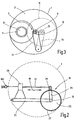
- FIG. 3 shows a highly schematic representation within a housing 1 the space 3, in which there is a fluid to be filtered, dirt contaminated.
- space 3 In space 3 is freely rotatable supply roll 5 with band-shaped filter material stored on a fluid-permeable core 7.
- the inside of the Kernes 7 located space 9 receives the filtered fluid, which the Winding 5 from outside to inside, d. H. from the room 3 ago flows through, where the filtration process takes place by deep filtration action and itself the filtered dirt particles at the outermost layers of Lagerwikkels 5 settle.
- the increase of the pressure difference between the space 3 with the to be filtered Fluid and the space 9 with the filtered fluid as it is due the increase in the degree of soiling of the outer layers of the supply roll 5 results, serves as a control variable for the triggering of a feed operation for the band-shaped filter material. This is this from the supply winding 5 off and wound on a take-up reel 11. Which in this feed movement resulting directions of Vorratswikkel 5 and receiving windings 11 are indicated by arrows. Of the Take-up reel 11 is by a winding shaft 13 (see also Fig. 2) of the inventive drive device rotated.
- Fig. 2 shows schematically simplified as the whole designated 15 Ratchet drive, which due to the rotational movement of the winding shaft 13 reciprocating movements of an actuating rod 17 is generated.
- the in the direction of the double arrow 19 reciprocating movements of the Rod 17 lead to reciprocating pivotal movements of a the winding shaft 13 freely pivotable pawl lever 21, on which a for the engagement in the toothing 27 of a ratchet wheel 23 spring-loaded Pawl 25 is articulated.
- This pawl 25 acts with the sawtooth-like teeth 27 of the ratchet wheel 23 together so that only when moving the actuating rod 17 to the left in Fig. 2 a rotational movement of the Ratchet wheel 23 takes place counterclockwise.
- Fig. 1 Further details of the hydromechanical device for generating the reciprocating movement of the rod 17 are shown in Fig. 1.
- This device has a hydraulic accumulator in the form of a membrane memory 29, the membrane 31 is a movable separating element between a first memory space 33 and a second memory space 35 forms.
- a pressure plate 37, on the membrane 31 at the memory space 35 facing side rests, is firmly connected to the actuating rod 17, which, centrally located, in the longitudinal direction of the housing of the diaphragm storage 29 extends and during movements of the diaphragm 31 in this Longitudinal reciprocating (double arrow 19) is movable.
- the am Storage space 33 located end cap 39 forms not only one Guide for the actuating rod 17, but also has passages 41st on, via which the storage space 33 containing the fluid to be filtered Room 3 (see Fig. 3) of the band filter device is in communication, so that in the storage space 33 in operation, the pressure of the fluid to be filtered prevails.
- a compression spring 45 is supported, so that the membrane 31 and the actuating rod 17 for movement in the drawing to the right is biased in an end position shown in Fig. 1.
- the left side in Fig. 1 space 35 is up to a first fluid port 47 and a second fluid port 49 closed.
- One in the room 35 located control valve has a movable valve body 51.
- the valve body 51 indicated only schematically in FIG. 1 is simplified forms part of a poppet valve, through which, depending on the position of the valve body 51, each one of the fluid ports 47, 49 open and each other terminal 47, 49 can be closed.
- the valve body 51 is controllable by the movement of the diaphragm 31. In the case shown in FIG. 1, located on the right side end position of the membrane 31 is located the valve body 51 in a position in which the first fluid port 47th opened and he second fluid port 49 is closed.
- This Kippsprungwerk has an am Valve body 41 articulated, displaceable in a sleeve 53 against spring load guided actuating plunger 55 on.
- the sleeve 53 is over a fork-shaped link 57 with the facing end 59 of the actuating rod 17 articulated.
- a roller 61 At the free end of the sleeve 53 is located a roller 61 which rolls on the inside of the diaphragm accumulator housing.
- the operation of the drive device is as follows: in the in Fig. 1st shown working position prevails in the storage space 33, the pressure of to be filtered fluids.
- the pressure prevailing in the other storage space 35 is by means of a fluid port 47 located pressure relief valve 69 set on a contrast lower pressure.
- the pressure of the fluid to be filtered and thus the Pressure in the storage space 33 increases to a value at which the effect the return spring 45, which the diaphragm 31 in the right in Fig. 1 Seeking to end position, overcome, the membrane moves 31 and thus the actuating rod 17 in the drawing to the left, wherein see Fig. 2, the winding shaft 13 is rotated by means of the ratchet drive 15 is, so that by the drive of the take-up reel 11 by means of Wikkelwelle 13 spent filter material from the supply roll 5 and on the receiving winding 11 is wound up.
- the tipping hopper Upon reaching the left-side end position of the diaphragm 31 (this position is not shown) the tipping hopper abruptly strikes the valve body 51 around, so that due to the pivoting movement according to the arrow 67 (Fig. 1), the fluid port 49 is opened and the fluid port 47 closed becomes.
- the fluid port 49 is connected to the fluid to be filtered (space 3 in Fig. 3), so that now in the storage space 35, the same pressure as in the storage space 33 prevails, whereby the membrane 31 through the Restoring force of the spring 45 again in the drawing to the right in the in Fig. 1 shown end position is moved, wherein the Kippsprungwerk the Valve body 51 in turn turns into the valve position shown in FIG. 1, so that the initial state is reached again, d. H. a working game is completed.
- fluid port 47 could be the fluid port 47 directly with the filtered fluid containing space 9 (FIG. 3) be connected, where there is a lower pressure level than in the room 3.
- a pressure relief valve 69 is the resulting Steering amount in the (not shown) tank before the band filter device dissipated.
- FIGS. 2 and 3 show that the entire drive device in the housing. 1 a respective band filter device is installed. As shown in Fig. 3 can be removed is, as the operation continues, where filter material successively from the supply roll 5 and wound on the exception windings 11 the latter being larger in diameter while the diameter of the supply roll 5 gets smaller.
- FIGS. 2 and 3 are in adaptation to this circumstance, the winding shaft 13 and the take-up reel 11 at a pivotally mounted rocker 71 attached. As shown in FIG. 2, are on this rocker 71 attached all the components of the drive device, So both the diaphragm accumulator 29 with the actuating rod 17th as well as the thereby actuable ratchet drive 15 for the winding shaft 13.
- the entire drive device with the rocker 71 for adaptation movable to the winding diameter, so that the axis of rotation of the winding shaft 13 is displaceable, as shown in Fig. 3 with dashed lines is.
- the membrane memory 29 provided in the exemplary embodiment can use a different type of hydraulic accumulator with movable separator find to the actuator rod 17 of the drive device out and to press on.
- the mentioned hydraulic accumulator is not used in the classic sense of storing hydraulic energy but is to understand here more as a media separator, being a separator 31 two storage spaces 33,35 separating media separated from each other.
- the storage space 35 with the tank via the valve 69 connected.
- the size of the pressure difference or the dynamic pressure leaves to adjust over the spring force of said valve 69.
- a safety function is realized, which triggers an exhaust event, for example, at inadmissibly high Pressure peaks in the respective storage space. Because of the fluid port 49th the storage space 35 is connectable to the dirty side of the device, may be provided before the terminal 49, a corresponding filter device be (not shown).
Landscapes
- Chemical & Material Sciences (AREA)
- Chemical Kinetics & Catalysis (AREA)
- Fluid-Pressure Circuits (AREA)
- Filtration Of Liquid (AREA)
Abstract
Description
- einen Hydrospeicher mit einem einen ersten und einen zweiten Speicherraum trennenden, beweglichen Trennelement, das auf seiner an den ersten Speicherraum angrenzenden Seite mit dem darin herrschenden Druck des zu filternden Fluids beaufschlagbar ist,
- eine eine Bewegung des Trennelementes in die Vorschubbewegung umsetzende Mechanik und
- eine Drucksteuereinrichtung, um in dem zweiten Speicherraum in Abhängigkeit von der Höhe des Druckes und/oder des Verschmutzungsgrades des filternden Fluides einen demgegenüber niedrigeren, die Bewegung des Trennelementes bewirkenden Druck zu erzeugen.
- Fig. 1 einen schematisch stark vereinfachten Längsschnitt nur des Membranspeichers des Ausführungsbeispieles der erfindungsgemäßen Antriebsvorrichtung;
- Fig. 2 eine schematisierte Funktionsskizze des Ausführungsbeispieles der Antriebsvorrichtung und
- Fig. 3 eine schematisierte Funktionsskizze in Form einer Draufsicht auf denjenigen Teil einer Bandfiltereinrichtung, in dem ein Vorratswickel bandförmigen Filtermaterials und ein mittels der erfindungsgemäßen Antriebsvorrichtung zu drehender Wickel für das Aufwickeln benutzten Filtermaterials untergebracht sind.
Claims (16)
- Hydromechanische Antriebsvorrichtung einer Bandfiltereinrichtung, um Vorschubbewegungen des bandförmigen Filtermaterials der Bandfiltereinrichtung in Abhängigkeit von dem in dem zu filternden Fluid herrschenden Druck zu erzeugen, miteinem Hydrospeicher (29) mit einem einen ersten (33) und einen zweiten Speicherraum (35) trennenden, beweglichen Trennelement (31), das auf seiner an den ersten Speicherraum (33) angrenzenden Seite mit dem darin herrschenden Druck des zu filternden Fluids beaufschlagbar ist,einer eine Bewegung des Trennelementes (31) in die Vorschubbewegung umsetzenden Mechanik (15, 17) undeiner Drucksteuereinrichtung (47, 49, 51), um in dem zweiten Speicher raum (35) in Abhängigkeit von der Höhe des Druckes und/oder Verschmutzungsgrades des zu filternden Fluides einen demgegenüber niedrigeren, die Bewegung des Trennelementes (31) bewirkenden Druck zu erzeugen.
- Antriebsvorrichtung nach Anspruch 1, dadurch gekennzeichnet, dass die Drucksteuereinrichtung zwei am zweiten Speicherraum (35) des Hydrospeichers (29) vorgesehene Fluidanschlüsse (47 und 49) aufweist, über deren ersten Anschluß (49) in diesem Speicherraum (35) der gegenüber dem Druck im ersten Speicherraum (33)niedrigere Druck erzeugbar ist und über deren zweiten Anschluß (49) im zweiten Speicherraum (35) der auch im ersten Speicherraum (33) herrschende Druck er zeugbar ist, und dass die Drucksteuereinrichtung ein Steuerventil (51) besitzt, das durch die Bewegung des Trennelementes (31) betätigbar ist, um bei einer Endstellung des Trennelementes (31) den ersten Anschluß (47) frei zu geben und den zweiten Anschluß (49) zu sperren und bei der anderen Endstellung des Trennelementes (31) den zweiten Anschluß (49) frei zu geben und den ersten Anschluß (47) zu sperren.
- Antriebsvorrichtung nach Anspruch 2, dadurch gekennzeichnet, dass der zweite Fluidanschluß (49) sowie der erste Speicherraum (33) des Hydrospeichers (29) mit dem zu filternden Fluid verbunden sind.
- Antriebsvorrichtung nach Anspruch 2 oder 3, dadurch gekennzeichnet, dass der erste Fluidanschluß (47) mit einem Druckbegrenzungsventil (69) verbunden ist, das auf einen Druckwert einstellbar ist, der niedriger ist als der am zweiten Fluidanschluß (49) anstehende Druck des zu filternden Fluids.
- Antriebsvorrichtung nach Anspruch 2 oder 3, dadurch gekennzeichnet, dass der erste Fluidanschluß (47) mit dem durch das bandförmige Filtermaterial gefilterten Fluid (9) verbunden ist, das einen gegenüber dem Druck des zu filternden Fluids niedrigeren Druck aufweist.
- Antriebsvorrichtung nach einem der Ansprüche 2 bis 5, dadurch gekennzeichnet, dass das Steuerventil (51) mit dem beweglichen Trennelement (31) über eine das Umschalten des Steuerventils (51) nur in den Endstellungen des Trennelementes (31) bewirkende kinematische Einrichtung (53,55) verbunden ist.
- Antriebsvorrichtung nach Anspruch 6, dadurch gekennzeichnet, dass als kinematische Einrichtung ein überzentrisches Kippsprungwerk (53,55) für im wesentlichen schlagartiges Öffnen und Schließen der entsprechenden Fluidanschlüsse (47,49) vorgesehen ist.
- Antriebsvorrichtung nach einem der Ansprüche 2 bis 7, dadurch gekennzeichnet, dass das Trennelement (31) mittels einer Federanordnung (45) in seine der Offenstellung des ersten Fluidanschlusses (47) und der Schließstellung des zweiten Fluidanschlusses (49) entsprechende Endstellung vorgespannt ist.
- Antriebsvorrichtung nach Anspruch 8, dadurch gekennzeichnet, dass das bewegliche Trennelement (31) des Hydrospeichers (29) mit einer durch dessen Bewegung in Längsrichtung hin und hergehend verschiebbaren Betätigungsstange (17) verbunden ist, die Teil der die Bewegung des Trennelementes (31) in die Vorschubbewegung des Filtermaterials umsetzenden Mechanik ist.
- Antriebsvorrichtung nach Anspruch 9, gekennzeichnet durch einen mittels der hin und hergehenden Betätigungsstange (17) antreibbaren Ratschenantrieb (15) mit einem durch die Bewegung der Betätigungsstange (17) nur in einem Drehsinne antreibbaren Klinkenrad (23) , das mit einer Wickelwelle (13) für den Antrieb eines Wickels (11) des bandförmigen Filtermaterials verbunden ist.
- Antriebsvorrichtung nach Anspruch 10, dadurch gekennzeichnet, dass die die Vorschubbewegung des bandförmigen Filtermaterials erzeugende Mechanik an einer Schwinge (71) angebracht ist, die für eine eine Anpassung an unterschiedliche Wickeldurchmesser des bandförmigen Filtermaterials ermöglichende Verlagerung der Drehachse der Wickelwelle (13) schwenkbar gelagert ist.
- Antriebsvorrichtung nach einem der Ansprüche 1 bis 11, dadurch gekennzeichnet, dass der Hydrospeicher (29) in dem oder an dem das zu filternde Fluid enthaltenden Raum (3) der betreffenden Bandfiltereinrichtung angeordnet ist und sein erster Speicherraum (33) einen den Eintritt des zu filternden Fluides ermöglichenden Durchlaß (41) aufweist.
- Antriebsvorrichtung nach den Ansprüchen 7 und 12, dadurch gekennzeichnet, dass das Trennelement (31) des Hydrospeichers mit einem Steuerglied (57) des das Steuerventil (51) betätigenden Kippsprungwerkes (53,55) gekuppelt ist.
- Antriebsvorrichtung nach einem der Ansprüche 1 bis 13, dadurch gekennzeichnet, dass als Hydrospeicher ein Membranspeicher (29) vorgesehen ist.
- Antriebsvorrichtung nach den Ansprüchen 13 und 14, dadurch gekennzeichnet, dass eine an der Membran (31) des Membranspeichers (29) anliegende Druckplatte (37) vorgesehen ist, die mit dem Steuerglied (57) des Kippsprungwerkes (53,55) gekuppelt ist.
- Antriebsvorrichtung nach Anspruch 15, dadurch gekennzeichnet, dass das Kippsprungwerk (53,55) und das Steuerventil (51) im zweiten Speicherraum (35) des Membranspeichers (29) untergebracht sind.
Applications Claiming Priority (3)
| Application Number | Priority Date | Filing Date | Title |
|---|---|---|---|
| DE10236085A DE10236085B3 (de) | 2002-08-07 | 2002-08-07 | Hydromechanische Antriebsvorrichtung |
| DE10236085 | 2002-08-07 | ||
| PCT/EP2003/007162 WO2004018075A1 (de) | 2002-08-07 | 2003-07-04 | Hydromechanische antriebsvorrichtung |
Publications (2)
| Publication Number | Publication Date |
|---|---|
| EP1526908A1 EP1526908A1 (de) | 2005-05-04 |
| EP1526908B1 true EP1526908B1 (de) | 2005-11-23 |
Family
ID=29762126
Family Applications (1)
| Application Number | Title | Priority Date | Filing Date |
|---|---|---|---|
| EP03792175A Expired - Lifetime EP1526908B1 (de) | 2002-08-07 | 2003-07-04 | Hydromechanische antriebsvorrichtung |
Country Status (4)
| Country | Link |
|---|---|
| US (1) | US7381324B2 (de) |
| EP (1) | EP1526908B1 (de) |
| DE (2) | DE10236085B3 (de) |
| WO (1) | WO2004018075A1 (de) |
Families Citing this family (4)
| Publication number | Priority date | Publication date | Assignee | Title |
|---|---|---|---|---|
| DE102009060251B4 (de) * | 2009-12-23 | 2016-07-07 | Sms Group Gmbh | Steuermittel zur Zuführung eines fluiden Mediums, Verwendung eines solchen Steuermittels sowie Reversierende Antriebsspindel steuerbar durch ein solches Steuermittel |
| CN108104181B (zh) * | 2017-12-15 | 2020-04-17 | 重庆中航建设(集团)有限公司 | 一种建筑基坑作业装置 |
| CN112473962B (zh) * | 2020-12-02 | 2021-12-24 | 陕西满意水泥有限责任公司 | 水泥生产分级打散装置 |
| CN117180864B (zh) * | 2023-11-07 | 2024-01-09 | 德州欣宇电气自动化设备有限公司 | 一种大气污染防治用空气过滤器 |
Family Cites Families (8)
| Publication number | Priority date | Publication date | Assignee | Title |
|---|---|---|---|---|
| GB1154101A (en) * | 1965-07-20 | 1969-06-04 | Metalwash Machinery Corp | Improvement in or relating to Washing Apparatus, including a Travelling Band Filter. |
| US4054521A (en) * | 1972-05-10 | 1977-10-18 | Brunswick Corporation | Indexing mechanism |
| AU539155B2 (en) * | 1979-10-29 | 1984-09-13 | George Arthur Howard | Cleaning screen openings |
| DE9217783U1 (de) * | 1992-02-21 | 1993-03-04 | FAB Filtertechnik Anlagenbau Fischer, van Betuw & Co GmbH, 7302 Ostfildern | Unterdruck-Tauchfiltereinrichtung |
| FR2698283B1 (fr) * | 1992-11-23 | 1995-03-10 | Pierre Conil | Filtre à bande porteuse et à toile perdue humide. |
| DE9301154U1 (de) * | 1993-01-28 | 1993-04-15 | Bürener Maschinenfabrik GmbH, 4793 Büren | Vorrichtung zum Filtern von Flüssigkeiten |
| DE4311297A1 (de) * | 1993-04-06 | 1994-10-13 | Gessner & Co Gmbh | Regenerierbare Separationselemente, deren Verwendung und dafür geeignete Gehäuse |
| DE10126443B4 (de) * | 2001-05-31 | 2006-04-20 | Hydac Filtertechnik Gmbh | Vorrichtung zur Filtration und Filterwechselkassette |
-
2002
- 2002-08-07 DE DE10236085A patent/DE10236085B3/de not_active Expired - Fee Related
-
2003
- 2003-07-04 EP EP03792175A patent/EP1526908B1/de not_active Expired - Lifetime
- 2003-07-04 DE DE50301764T patent/DE50301764D1/de not_active Expired - Lifetime
- 2003-07-04 WO PCT/EP2003/007162 patent/WO2004018075A1/de not_active Ceased
- 2003-07-04 US US10/521,740 patent/US7381324B2/en not_active Expired - Fee Related
Also Published As
| Publication number | Publication date |
|---|---|
| US20050252046A1 (en) | 2005-11-17 |
| US7381324B2 (en) | 2008-06-03 |
| WO2004018075A1 (de) | 2004-03-04 |
| EP1526908A1 (de) | 2005-05-04 |
| DE10236085B3 (de) | 2004-01-22 |
| DE50301764D1 (de) | 2005-12-29 |
Similar Documents
| Publication | Publication Date | Title |
|---|---|---|
| EP0299541B1 (de) | Sicherheitseinrichtung für ein von einer Bedienungsperson zu handhabendes Gerät | |
| EP1250533B1 (de) | Hydropneumatischer druckspeicher | |
| DE202014104200U1 (de) | Rückspülfilter und Filtereinsatz hierfür | |
| DE2512480C3 (de) | Ventilvorrichtung für einen hydraulisch betätigbaren elektrischen Leistungsschalter | |
| DE2462651B1 (de) | Betonpumpe | |
| DE2335214B2 (de) | Selbstreinigender Flüssigkeitsfilter | |
| EP0402559A2 (de) | Umschaltarmatur | |
| DE7831128U1 (de) | Rueckspuelfilter | |
| DE69431543T2 (de) | ventilanordnung | |
| EP1526908B1 (de) | Hydromechanische antriebsvorrichtung | |
| DE2419654B2 (de) | Koaxialventil | |
| DE2445587A1 (de) | Druckkompensierendes wegeventil | |
| DE102017115054A1 (de) | Hydropneumatische Vorrichtung zur Druckübersetzung | |
| EP0089384B1 (de) | Einrichtung zur Versorgung von ortsveränderlichen Verbrauchern mit einem Druckfluid | |
| DE102022104857A1 (de) | Einrichtung und Verfahren zur Rückspülung eines Filters sowie System zur Filterung | |
| DE102009058027A1 (de) | Vorrichtung zur Höhenverstellung eines Fahrzeugaufbaus | |
| EP0489331A1 (de) | Eigenmediumbetätigtes, durch einen Magnetanker gesteuertes Servoventil | |
| EP1891652A1 (de) | Kraftspeicher | |
| EP0278333B1 (de) | Steuervorrichtung für einen Rohrtrenner | |
| DE3309787A1 (de) | Fluessigkeitsfilter | |
| DE2123263C2 (de) | Hydraulischer Antrieb für Eilvorlauf, Arbeitshub und Eilrücklauf | |
| DE1241803B (de) | Absperrvorrichtung zum automatischen, periodischen Entschlammen von Filterkerzen durch Rueckspuelung | |
| DE2834420C2 (de) | Lenkventil | |
| DE2435354C3 (de) | Doppeltwirkender pneumatischer Stellantrieb | |
| DE1270906B (de) | Steuerschieber |
Legal Events
| Date | Code | Title | Description |
|---|---|---|---|
| PUAI | Public reference made under article 153(3) epc to a published international application that has entered the european phase |
Free format text: ORIGINAL CODE: 0009012 |
|
| 17P | Request for examination filed |
Effective date: 20041117 |
|
| AK | Designated contracting states |
Kind code of ref document: A1 Designated state(s): AT BE BG CH CY CZ DE DK EE ES FI FR GB GR HU IE IT LI LU MC NL PT RO SE SI SK TR |
|
| GRAP | Despatch of communication of intention to grant a patent |
Free format text: ORIGINAL CODE: EPIDOSNIGR1 |
|
| RBV | Designated contracting states (corrected) |
Designated state(s): DE FR GB |
|
| RAP1 | Party data changed (applicant data changed or rights of an application transferred) |
Owner name: HYDAC FILTERTECHNIK GMBH |
|
| GRAS | Grant fee paid |
Free format text: ORIGINAL CODE: EPIDOSNIGR3 |
|
| GRAA | (expected) grant |
Free format text: ORIGINAL CODE: 0009210 |
|
| AK | Designated contracting states |
Kind code of ref document: B1 Designated state(s): DE FR GB |
|
| REG | Reference to a national code |
Ref country code: GB Ref legal event code: FG4D Free format text: NOT ENGLISH |
|
| GBT | Gb: translation of ep patent filed (gb section 77(6)(a)/1977) | ||
| REF | Corresponds to: |
Ref document number: 50301764 Country of ref document: DE Date of ref document: 20051229 Kind code of ref document: P |
|
| ET | Fr: translation filed | ||
| PLBE | No opposition filed within time limit |
Free format text: ORIGINAL CODE: 0009261 |
|
| STAA | Information on the status of an ep patent application or granted ep patent |
Free format text: STATUS: NO OPPOSITION FILED WITHIN TIME LIMIT |
|
| 26N | No opposition filed |
Effective date: 20060824 |
|
| PGFP | Annual fee paid to national office [announced via postgrant information from national office to epo] |
Ref country code: GB Payment date: 20140502 Year of fee payment: 12 |
|
| PGFP | Annual fee paid to national office [announced via postgrant information from national office to epo] |
Ref country code: FR Payment date: 20140513 Year of fee payment: 12 |
|
| PGFP | Annual fee paid to national office [announced via postgrant information from national office to epo] |
Ref country code: DE Payment date: 20140805 Year of fee payment: 12 |
|
| REG | Reference to a national code |
Ref country code: DE Ref legal event code: R119 Ref document number: 50301764 Country of ref document: DE |
|
| GBPC | Gb: european patent ceased through non-payment of renewal fee |
Effective date: 20150704 |
|
| PG25 | Lapsed in a contracting state [announced via postgrant information from national office to epo] |
Ref country code: GB Free format text: LAPSE BECAUSE OF NON-PAYMENT OF DUE FEES Effective date: 20150704 Ref country code: DE Free format text: LAPSE BECAUSE OF NON-PAYMENT OF DUE FEES Effective date: 20160202 |
|
| REG | Reference to a national code |
Ref country code: FR Ref legal event code: ST Effective date: 20160331 |
|
| PG25 | Lapsed in a contracting state [announced via postgrant information from national office to epo] |
Ref country code: FR Free format text: LAPSE BECAUSE OF NON-PAYMENT OF DUE FEES Effective date: 20150731 |