EP1526495A2 - Gliederpuppe, insbesondere in Form eines menschlichen Körpers - Google Patents
Gliederpuppe, insbesondere in Form eines menschlichen Körpers Download PDFInfo
- Publication number
- EP1526495A2 EP1526495A2 EP04025124A EP04025124A EP1526495A2 EP 1526495 A2 EP1526495 A2 EP 1526495A2 EP 04025124 A EP04025124 A EP 04025124A EP 04025124 A EP04025124 A EP 04025124A EP 1526495 A2 EP1526495 A2 EP 1526495A2
- Authority
- EP
- European Patent Office
- Prior art keywords
- servo
- mannequin
- link
- pulley
- axle
- Prior art date
- Legal status (The legal status is an assumption and is not a legal conclusion. Google has not performed a legal analysis and makes no representation as to the accuracy of the status listed.)
- Withdrawn
Links
- 230000005540 biological transmission Effects 0.000 claims description 22
- 230000033001 locomotion Effects 0.000 description 24
- 238000012545 processing Methods 0.000 description 4
- 238000010521 absorption reaction Methods 0.000 description 1
- 238000013459 approach Methods 0.000 description 1
- 238000010276 construction Methods 0.000 description 1
- 230000001419 dependent effect Effects 0.000 description 1
- 238000013461 design Methods 0.000 description 1
- 238000011161 development Methods 0.000 description 1
- 238000010586 diagram Methods 0.000 description 1
- 230000010355 oscillation Effects 0.000 description 1
- 230000008092 positive effect Effects 0.000 description 1
- 238000005096 rolling process Methods 0.000 description 1
- 238000007493 shaping process Methods 0.000 description 1
- 238000004904 shortening Methods 0.000 description 1
- 230000003068 static effect Effects 0.000 description 1
- 238000012546 transfer Methods 0.000 description 1
Images


Classifications
-
- A—HUMAN NECESSITIES
- A63—SPORTS; GAMES; AMUSEMENTS
- A63H—TOYS, e.g. TOPS, DOLLS, HOOPS OR BUILDING BLOCKS
- A63H3/00—Dolls
- A63H3/36—Details; Accessories
- A63H3/48—Mounting of parts within dolls, e.g. automatic eyes or parts for animation
-
- A—HUMAN NECESSITIES
- A63—SPORTS; GAMES; AMUSEMENTS
- A63H—TOYS, e.g. TOPS, DOLLS, HOOPS OR BUILDING BLOCKS
- A63H3/00—Dolls
- A63H3/36—Details; Accessories
- A63H3/46—Connections for limbs
-
- G—PHYSICS
- G09—EDUCATION; CRYPTOGRAPHY; DISPLAY; ADVERTISING; SEALS
- G09F—DISPLAYING; ADVERTISING; SIGNS; LABELS OR NAME-PLATES; SEALS
- G09F19/00—Advertising or display means not otherwise provided for
- G09F19/02—Advertising or display means not otherwise provided for incorporating moving display members
- G09F19/08—Dolls, faces, or other representations of living forms with moving parts
-
- G—PHYSICS
- G09—EDUCATION; CRYPTOGRAPHY; DISPLAY; ADVERTISING; SEALS
- G09F—DISPLAYING; ADVERTISING; SIGNS; LABELS OR NAME-PLATES; SEALS
- G09F19/00—Advertising or display means not otherwise provided for
- G09F19/02—Advertising or display means not otherwise provided for incorporating moving display members
- G09F19/08—Dolls, faces, or other representations of living forms with moving parts
- G09F2019/086—Dolls
Definitions
- the invention relates to a mannequin, in particular in the form of a human Body according to the preamble of claim 1.
- mannequins are for the presentation of clothing and accessories in shop windows and displays used for example in department stores.
- mannequins are known, especially in the form of a human body whose posture is fixed unchangeable.
- the disadvantage is that such mannequins remain rigid during the presentation in the predetermined posture.
- a mannequin must be maintained for each desired posture.
- manikins are known, in particular in the form of a human body, whose posture is at least during the construction and reconstruction of a window display by hand changeable.
- a disadvantage of the use of such manikins is that they remain rigid during the presentation in the previously set posture.
- manikins especially in the form of a human body whose posture are continuously changed by driven movable members during the presentation. In particular, the drives of the movable members have disadvantages.
- Servomotors and stepper motors each have a high weight and can only be used with complex control electronics. Even pneumatic cylinders must be controlled consuming. In addition, the provision of pneumatic energy makes further technical demands.
- the use of linear motors in turn requires complex control electronics and is characterized by high costs disadvantageous. Manikins with such drive elements are expensive and tend due to their high weight to strong natural oscillations.
- WO 94/01198 a mannequin for simulating the running movement of a rotor is known in which by means of a servo on several belt transmissions, the rotational movement of the servo on different waves, z. B. for storage of the leg approach or arm attachment, transferred and implemented there by means of lever mechanism in pivotal movements.
- the disadvantage is that in particular the arm posture is fixed and not freely movable.
- the mannequin can be used only to emulate the running motion of a runner. Other positions of the mannequin can not be realized in this way.
- the mannequin is difficult to remove and tighten due to the rigid arm posture, whereby the handling of the mannequin is difficult.
- the servo is a very compact drive unit and includes a motor, a gearbox and corresponding control electronics.
- the drive of the servo implements a rotation angle of ⁇ 90 ° on its output shaft.
- the mannequin has a plurality of links that are connected to each other via at least one hinge or at least one hinge joint, each of these joints is designed to be drivable with a servo.
- Two link elements of a link of a mannequin are coaxially aligned with each other and articulated by means of a hinge connector.
- Both the first link element and the second link element each have a servo fixedly connected to the respective link element.
- the output pins of the servos are each rotatably connected to the joint connector.
- one servo realizes a coaxial rotational movement and the other servo realizes a pivoting movement of one link element to the other link element of the link of the mannequin.
- a disadvantage of the hinges designed as hinge joints is that all occurring static and dynamic forces are received directly in both the articulated arm and in the output shaft of the servo.
- a disadvantage of the hinges designed as hinges is that the angular momentum of the output shaft of the servos is transmitted directly to the respective member element of a link.
- the invention is therefore based on the object, a generic mannequin, especially in the form of a human body, so that the moving Members of the mannequin have a higher durability with greater load capacity and realize a smooth movement.
- the servo is equipped with a transmission gear and thereby the power transmission and the movement can be varied by changing the transmission ratio.
- this can increase the scope of the animation, in which the angular velocities, but also the torques, can be changed over a large area.
- the range of use of the servo between predefined limits can be limited and thus the servo can be optimized with the help of the transmission ratio. If smaller angular velocities and / or torques are to be realized with the predefined limits, then the servo can also be made less powerful and therefore smaller.
- the weight is absorbed by the hinges and the torque absorption by the servos. This increases the stability of the mannequin. At the same time, the load and wear of the output shaft of the servos are significantly reduced. It is also advantageous that the thru-axle is rotatably connected to the first member member and rotatably connected to the second member element, as well as the share forces of the dynamic forces are absorbed by the thru axle in addition to the weight forces and thus the servo is further relieved.
- a belt transmission can be used in the hinge and the hinge joint.
- the elastic properties of the belt also have a positive effect on the quality of the animations and on the service life of the servos.
- the hinge joint is flat and has four joints, and a further thru axle is located between a lever and a connecting rod, the length of the lever and / or the connecting rod can be adjusted. Then the power transmission and the radius of the movement path can also be varied, resulting in even more diverse applications of the manikin.
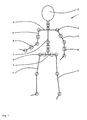
- the mannequin according to the invention in particular in the form of a human body according to FIG. 1 consists of a framework 1 and a head 2.
- the framework 1 is simplified in a simplified manner to the human skeleton and has a vertically arranged backbone 3, on which a shoulder bracket 4 and a Hrichausleger 5 are each mounted horizontally.
- the shoulder bracket 4 is arranged approximately at the level of the shoulder and the H predominantlyausleger 5 approximately at the level of the hip of the mannequin.
- At the outer ends of the shoulder arm 4 are each a right arm member 6 and a left arm member 6 'attached.
- At the outer ends of the H favorauslegers 5 are each a right leg member 7 and a left leg member 7 'attached.
- both the shoulder bracket 4, the Hefficientausleger 5, the arm members 6, 6 'and the leg links 7, 7' are divided into further link elements.
- the link elements of the arm members 6, 6 'are designed to be movable relative to one another by means of rotary joints 8 and hinge joints 9.
- the link elements of the leg links 7, 7 'are in turn designed to be movable relative to one another by means of rotary joints 8.
- the backbone 3 in turn has a plurality of hinges 8 and hinge joints. 9
- the frame 1 of the mannequin is surrounded by a shell, not shown, which simulates a human body. The size of the frame 1 and the appearance of the head 2 and the shell are interpretable according to individual requirements.
- a hinge joint 9 is shown in a first embodiment.
- further hinge joints 9 are constructed in the same way, so that on the Presentation and explanation is omitted.
- the arm member 6 in a first member member 10 and a second member element 10 'divided, which are designed to pivot each other.
- the ends of the limb elements 10, 10 ' are by means of a plug-in axis 11 and rotatable with each other connected.
- a servo 12 is attached on the first link member 10.
- the servo 12 is supplied with data and energy by means not shown electrical lines.
- On an output shaft 13 of the servo 12 a first pulley 14 is rotatably mounted.
- the thru-axle 11 is non-rotatable with the second link element 10 'and with the second Pulley 14 'connected.
- On both pulleys 14, 14 ' is a circumferential Belt 15 is arranged.
- the angular velocity of the output shaft 13 of the servo 12th is on the angular velocity of the arm member element 10 'about the thru axle 11 and is determined by the ratio of the diameters of the pulleys 14, 14 'significantly influenced each other.
- the belt 15 is also a transmission by means of gears, Timing belt or chains conceivable.
- the hinge joint 9 is again exemplary in a second embodiment shown on the arm member 6.
- the arm member 6 is again in two member elements 10, 10 'shared. These are also designed to pivot to each other and connected by means of the thru-axle 11.
- On the first link element 10 is by means of a holding element 16, the servo 12 attached.
- the servo 12 is again not by means illustrated electrical lines with data and energy supplied.
- On the output shaft 13 of the servo 12 is a lever 17 having an end for transmitting the Torque of the servo 12 mounted rotatably.
- the other end of the lever 17 is rotatably mounted by means of a thru-axle 18 at one end of a connecting rod 19, wherein the other end of the connecting rod 19 in turn by means of a thru-axle 20 is rotatably connected to a holding member 21, which on the second member element 10 'is attached.
- Both the length of the lever 17, as well as the connecting rod 19, is executed changeable within limits.
- the axis distances between the output shaft 13 of the servo 12 and the thru axle 18, between the thru axles 18 and 20, between the thru axle 20 and 11 and between the thru axle 11 and the output shaft 13 of the servo 12 form a four-bar linkage. It is the Angular velocity of the output shaft 13 of the servo 12 to the angular velocity of the second link element 10 'is tuned to the thru-axle 11 and is determined by the ratios of these distances to each other significantly.
- one of the swivel joints 8 is shown by way of example on the arm member 6. In this case, more swivel joints 8 are constructed in the same way, so that their representation and explanation is omitted.
- the arm member 6 is in turn divided into the first member member 10 and the second member member 10 'and rotatable to each other.
- the ends of the member members 10, 10 ' are coaxially aligned with each other.
- the end of the second link element 10 'relative to the first member member 10 has a smaller diameter, which thus forms the plug-in axis 22.
- This thru-axle 22 serves as a carrier of an outer roller bearing 23 and projects together with the roller bearing 23 into the corresponding tubular shaped end of the first member element 10.
- the servo 12 is fixed by means of a holding element 16 '.
- the servo 12 is again supplied by means not shown electrical lines with data and energy.
- a first pulley 14 for transmitting the torque of the servo 12 is rotatably mounted.
- the second link element 10 ' in turn has a centrically arranged second pulley 14', which in turn is non-rotatably connected to the second link element 10 '.
- the pulleys 14, 14 ' are aligned with each other so that the circulation of a belt 15 for transmitting the rotational movement of the output shaft 13 of the servo 12 of the first member member 10 is ensured on the second member element 10'.
- the angular velocity of the output shaft 13 of the servo 12 is matched to the angular velocity of the arm member element 10 'and is significantly influenced by the ratio of the diameter of the pulleys 14, 14' to each other.
- transmission by means of the pulleys 14, 14 'and the belt 15 transmission by means of toothed wheels, toothed belts or chains is also conceivable here.
- the scheme shown in Fig. 7 shows that, by means of a on a personal computer installed software, preprogrammed motion sequence by means of a data transmission element on a data processing unit, on the mannequin installed, is transferable.
- the data processing unit of the manikin has a program memory for storing the preprogrammed motion sequences, a microprocessor as a controller for controlling each of the servos 1 ... n of the associated Swivels 10 or hinge joints 11 of the limbs of the mannequin.
- the Control of the servos 12 is according to the preprogrammed motion sequence on the realization of a soft flowing movement of the limbs of the mannequin designed as a lifelike animation.
- the one by one Servos 12 converted control commands are each either by means of the corresponding Swivel joints 8 or the corresponding hinge joints 9 on the link elements the arm members 6, 6 ', the leg links 7, 7' and the backbone 3 of the mannequin transfer.
- the simultaneous control generates in its implementation a flowing movement of the mannequin.
Landscapes
- Business, Economics & Management (AREA)
- Accounting & Taxation (AREA)
- Marketing (AREA)
- Physics & Mathematics (AREA)
- General Physics & Mathematics (AREA)
- Engineering & Computer Science (AREA)
- Theoretical Computer Science (AREA)
- Toys (AREA)
Abstract
Description
Weiterhin sind Gliederpuppen, insbesondere in Form eines menschlichen Körpers, bekannt, deren Körperhaltung zumindest während des Auf- und Umbaus einer Schaufensterauslage von Hand veränderbar ist. Nachteilig bei der Verwendung derartiger Gliederpuppen ist, dass auch diese während der Präsentation starr in der zuvor eingestellten Körperhaltung verharren.
Bekannt sind nun Gliederpuppen, insbesondere in Form eines menschlichen Körpers, deren Körperhaltung durch angetriebene bewegliche Glieder während der Präsentation laufend veränderbar sind.
Dabei weisen insbesondere die Antriebe der beweglichen Glieder Nachteile auf. Servomotore und Schrittmotore besitzen jeweils ein hohes Eigengewicht und sind nur mit einer aufwendigen Steuerungselektronik verwendbar. Auch Pneumatikzylinder müssen aufwendig angesteuert werden. Zudem stellt die Bereitstellung pneumatischer Energie weitere technische Anforderungen. Der Einsatz von Linearmotoren erfordert seinerseits aufwendige Steuerelektronik und zeichnet sich durch hohe Kosten nachteilig aus. Gliederpuppen mit derartigen Antriebselementen sind teuer und neigen auf Grund deren hohen Eigengewichtes zu starken Eigenschwingungen.
In WO 94/01198 ist eine Gliederpuppe zur Nachbildung der Laufbewegung eines Läufers bekannt, bei der mittels eines Servos über mehrere Riemengetriebe die Rotationsbewegung des Servos auf verschieden Wellen, z. B. für Lagerung des Beinansatzes oder Armansatzes, übertragen und dort mittels Hebelgetriebe in Schwenkbewegungen umgesetzt werden.
Nachteilig ist aber, dass im speziellen die Armhaltung fest vorgegeben und nicht frei bewegbar ist. Damit kann die Gliederpuppe nur zur Nachbildung der Laufbewegung eines Läufers eingesetzt werden. Andere Positionen der Gliederpuppe lassen sich so nicht realisieren. Außerdem lässt sich die Gliederpuppe durch die steife Armhaltung nur schwer aus- und anziehen, wodurch der Handhabung der Gliederpuppe erschwert wird.
Zwei Gliedelemente eines Gliedes einer Gliederpuppe sind koaxial zueinander ausgerichtet und gelenkig mittels eines Gelenkverbinders verbunden. Sowohl das erste Gliedelement als auch das zweite Gliedelement verfügt jeweils über einen fest mit dem jeweiligen Gliedelement verbundenen Servo. Die Abtriebszapfen der Servos sind jeweils drehfest mit dem Gelenkverbinder verbunden. Dabei realisiert der eine Servo eine koaxiale Drehbewegung und der andere Servo eine Schwenkbewegung des einen Gliedelementes zu dem anderen Gliedelement des Gliedes der Gliederpuppe.
Nachteilig bei den als Scharniergelenken ausgelegten Gelenken ist, dass alle auftretenden statischen und dynamischen Kräfte direkt sowohl in den Gelenkausleger als auch in die Abtriebswelle des Servos eingehen. Nachteilig bei den als Drehgelenken ausgelegten Gelenken ist, dass der Drehimpuls der Abtriebswelle der Servos direkt auf das jeweilige Gliedelement eines Gliedes übertragen wird. Dies betrifft alle radialen Drehgelenke der Gliederpuppe. Als besonders nachteilig ergeben sich ein hoher Verschleiß der Gelenke. Die Folge sind instabile Glieder der Gliederpuppe und ein unharmonischer Bewegungsablauf. Durch die direkte Verbindung von Servo und Glied gibt es keine Möglichkeit zur variablen Gestaltung des Bewegungs- und Kräfteverlaufs während der Bewegung der Glieder.
Von Vorteil ist auch, dass die Steckachse drehfest mit dem ersten Gliedelement und drehbar mit dem zweiten Gliedelement verbunden ist, da durch die Steckachse neben den Gewichtskräften so auch ein Anteil der dynamischen Kräfte aufgenommen werden und damit das Servo weiter entlastet wird.
Als Übersetzungsgetriebe kann beim Drehgelenk und beim Scharniergelenk ein Riemengetriebe eingesetzt werden. Dann wirken sich zusätzlich die elastischen Eigenschaften des Riemens positiv auf die Qualität der Animationen und auf die Lebensdauer der Servos aus. Durch die Riemengetriebe wird ein weicheres Anfahren erreicht, wodurch sich fließende Bewegungsabläufe realisieren lassen, die einer lebensechten Animation sehr nah kommen. Außerdem wird das Servo durch ein geringeres Anfahrmoment weniger beansprucht, weshalb sich seine Lebensdauer erhöht.
Von Vorteil ist auch, dass als Übersetzungsgetriebe beim Scharniergelenk ein Hebelgetriebe eingesetzt werden kann, womit große Kräfte übertragen und dadurch Lasten z.B. an dem Armglied der Gliederpuppe angehängt werden können. Die größere Gestaltungsvielfalt einer Animation mit dieser Gliederpuppe zeigt sich dann z.B. darin, dass ein an dem Armglied befestigter Koffer den Bewegungsablauf der Gliederpuppe mitläuft.
Ist bei Hebelgetriebe das Scharniergelenk eben und viergelenkig ausgeführt und befmdet sich zwischen einem Hebel und einer Verbindungsstange eine weitere Steckachse, so ist der Hebel und/oder die Verbindungsstange in seiner Länge verstellbar. Dann kann die Kraftübertragung sowie der Radius des Bewegungsweges ebenfalls variiert werden, woraus sich noch vielfältigere Anwendungsmöglichkeiten der Gliederpuppe ergeben.
- Fig. 1
- eine schematische Darstellung einer Gliederpuppe, deren Glieder mittels Scharnier- und Drehgelenken beweglich ausgeführt sind,
- Fig. 2
- eine schematische Darstellung eines Scharniergelenks in einer ersten Ausführungsform in einer Seitenansicht,
- Fig. 3
- eine schematische Darstellung des Scharniergelenks der Fig. 2 in einer Draufsicht,
- Fig. 4
- eine schematische Darstellung eines Scharniergelenks in einer zweiten Ausführungsform in einer Seitenansicht,
- Fig. 5
- eine schematische Darstellung eines Drehgelenks in einer Vorderansicht,
- Fig. 6
- eine schematische Darstellung des Drehgelenks aus Fig. 5 in einer Seitenansicht,
- Fig. 7
- ein Schaubild zur Darstellung des Informationsflusses zur Ansteuerung der Antriebseinheiten der Gelenke der Glieder der Gliederpuppe.
Das Gerüst 1 der Gliederpuppe ist mit einer nicht dargestellten, einen menschlichen Körper nachbildenden Hülle umgeben. Die Größe des Gerüstes 1 und das Erscheinungsbild des Kopfes 2 und der Hülle sind entsprechend individueller Erfordernisse auslegbar.
In dem Bereich des Drehgelenkes 8 ist das Armglied 6 wiederum in das erste Gliedelement 10 und das zweite Gliedelement 10' geteilt und drehbar zueinander ausgeführt. Die Enden der Gliedelemente 10, 10' sind dazu koaxial zueinander ausgerichtet. Dabei weist das Ende des zweiten Gliedelementes 10' gegenüber dem ersten Gliedelement 10 einen kleineren Durchmesser auf, der damit die Steckachse 22 bildet. Diese Steckachse 22 dient als Träger einer äußeren Wälzlagerung 23 und ragt mitsamt der Wälzlagerung 23 in das entsprechend röhrenförmig gestaltete Ende des ersten Gliedelementes 10 hinein. Anstelle der Wälzlagerung 23 könnte auch eine Gleitlagerung vorgesehen sein. Auf dem ersten Armgliedelement 10 ist mittels eines Halteelementes 16' das Servo 12 befestigt. Das Servo 12 ist wieder mittels nicht dargestellter elektrischer Leitungen mit Daten und Energie versorgbar. Auf der Abtriebswelle 13 des Servos 12 ist eine erste Riemenscheibe 14 zur Übertragung des Drehmomentes des Servos 12 drehfest befestigt. Das zweite Gliedelement 10' verfügt seinerseits über eine zentrisch angeordnete zweite Riemenscheibe 14', die ihrerseits drehfest mit dem zweiten Gliedelement 10' verbunden ist. Die Riemenscheiben 14, 14' sind dabei so zueinander ausgerichtet, dass der Umlauf eines Riemens 15 zur Übertragung der Drehbewegung der Abtriebswelle 13 des Servos 12 des ersten Gliedelementes 10 auf das zweite Gliedelement 10' gewährleistet ist. Die Winkelgeschwindigkeit der Abtriebswelle 13 des Servos 12 ist auf die Winkelgeschwindigkeit des Armgliedelementes 10' abgestimmt und wird durch das Verhältnis der Durchmesser der Riemenscheiben 14, 14' zueinander maßgeblich beeinflusst. Anstelle einer Übertragung mittels der Riemenscheiben 14, 14' und des Riemens 15 ist auch hier eine Übertragung mittels Zahnrädern, Zahnriemen oder Ketten vorstellbar.
- 1
- Gerüst
- 2
- Kopf
- 3
- Rückgrat
- 4
- Schulterausleger
- 5
- Hüftausleger
- 6, 6'
- Armglied
- 7, 7'
- Beinglied
- 8
- Drehgelenk
- 9
- Scharniergelenk
- 10, 10'
- Gliedelement
- 11
- Steckachse
- 12
- Servo
- 13
- Abtriebswelle des Servos
- 14, 14'
- Riemenscheibe
- 15
- Riemen
- 16, 16'
- Halteelement
- 17
- Hebel
- 18
- Steckachse
- 19
- Verbindungsstange
- 20
- Steckachse
- 21
- Halteelement
- 22
- Steckachse
- 23
- Wälzlagerung
Claims (7)
- Gliederpuppe, insbesondere in Form eines menschlichen Körpers, bestehend aus mehreren Gliedelementen (10, 10'), die durch mehrere Drehgelenke (8) und/oder mehrere Scharniergelenke (9) miteinander verbunden sind, wobei jeweils zwei Gliedelemente (10, 10') durch einen Servo (12) antreibbar sind,
dadurch gekennzeichnet, dass das Servo (12) mit einem Übersetzungsgetriebe ausgerüstet ist. - Gliederpuppe nach Anspruch 1,
dadurch gekennzeichnet, dass das Übersetzungsgetriebe des Servos (12) beim Drehgelenk (8) und beim Scharniergelenk (9) ein Riemengetriebe ist. - Gliederpuppe nach Anspruch 2,
dadurch gekennzeichnet, dass das Riemengetriebe aus einer ersten Riemenscheibe (14), einer zweiten Riemenscheibe (14') und aus einem, über die Riemenscheiben (14, 14') umlaufenden Riemen (15) besteht, wobei die erste Riemenscheibe (14) koaxial und drehfest mit der Abtriebswelle (13) eines Servos (12) des ersten Gliedelementes (10) sowie die zweite Riemenscheibe (14') koaxial und drehfest mit der Steckachse (11, 22) verbunden ist. - Gliederpuppe nach Anspruch 3
dadurch gekennzeichnet, dass die Steckachse (11, 22) drehbar mit dem ersten Gliedelement (10) und drehfest mit dem zweiten Gliedelement (10') verbunden ist. - Gliederpuppe nach Anspruch 1,
dadurch gekennzeichnet, dass das Übersetzungsgetriebe des Servos (12) beim Scharniergelenk (9) ein Hebelgetriebe ist. - Gliederpuppe nach Anspruch 5
dadurch gekennzeichnet, dass das Scharniergelenk (9) eben und viergelenkig ausgeführt ist und sich zwischen einem Hebel (17) und einer Verbindungsstange (19) eine weitere Steckachse (18) befindet und dass der Hebel (17) und/oder die Verbindungsstange (19) in seiner Länge verstellbar ist. - Gliederpuppe nach Anspruch 4 oder 6,
dadurch gekennzeichnet, dass die axiale Ausrichtung der Abtriebswelle (13) des Servos (12) beim Drehgelenk (8) parallel und beim Scharniergelenk (9) im rechten Winkel zur Längsachse des Gliedelementes (10, 10') ist.
Applications Claiming Priority (2)
| Application Number | Priority Date | Filing Date | Title |
|---|---|---|---|
| DE20316424U DE20316424U1 (de) | 2003-10-24 | 2003-10-24 | Gliederpuppe, insbesondere in Form eines menschlichen Körpers |
| DE20316424U | 2003-10-24 |
Publications (2)
| Publication Number | Publication Date |
|---|---|
| EP1526495A2 true EP1526495A2 (de) | 2005-04-27 |
| EP1526495A3 EP1526495A3 (de) | 2006-05-03 |
Family
ID=32010633
Family Applications (1)
| Application Number | Title | Priority Date | Filing Date |
|---|---|---|---|
| EP04025124A Withdrawn EP1526495A3 (de) | 2003-10-24 | 2004-10-22 | Gliederpuppe, insbesondere in Form eines menschlichen Körpers |
Country Status (2)
| Country | Link |
|---|---|
| EP (1) | EP1526495A3 (de) |
| DE (1) | DE20316424U1 (de) |
Cited By (1)
| Publication number | Priority date | Publication date | Assignee | Title |
|---|---|---|---|---|
| GB2425491A (en) * | 2005-04-28 | 2006-11-01 | Lee Mcdonald | Articulated figure |
Families Citing this family (1)
| Publication number | Priority date | Publication date | Assignee | Title |
|---|---|---|---|---|
| AU2003261773A1 (en) * | 2002-08-29 | 2004-03-19 | Flower Robotics Inc. | Mannequin having drive section |
Family Cites Families (5)
| Publication number | Priority date | Publication date | Assignee | Title |
|---|---|---|---|---|
| US3731426A (en) * | 1971-10-13 | 1973-05-08 | Mattel Inc | Shape-changing figure toy |
| FR2656141B1 (fr) * | 1989-12-19 | 1992-03-06 | Chauvin Patrick | Annonceur public. |
| AU4576693A (en) * | 1992-07-14 | 1994-01-31 | Darren Gareth Saunders | Animated display |
| US6198247B1 (en) * | 1999-04-20 | 2001-03-06 | Steven Barr | Servo-articulated modules and robotic assemblies incorporating them |
| JP2002166375A (ja) * | 2000-11-29 | 2002-06-11 | Iwahiro Shimizu | 歩行型マネキン人形 |
-
2003
- 2003-10-24 DE DE20316424U patent/DE20316424U1/de not_active Expired - Lifetime
-
2004
- 2004-10-22 EP EP04025124A patent/EP1526495A3/de not_active Withdrawn
Non-Patent Citations (1)
| Title |
|---|
| None * |
Cited By (1)
| Publication number | Priority date | Publication date | Assignee | Title |
|---|---|---|---|---|
| GB2425491A (en) * | 2005-04-28 | 2006-11-01 | Lee Mcdonald | Articulated figure |
Also Published As
| Publication number | Publication date |
|---|---|
| EP1526495A3 (de) | 2006-05-03 |
| DE20316424U1 (de) | 2004-03-11 |
Similar Documents
| Publication | Publication Date | Title |
|---|---|---|
| EP1161357B1 (de) | Elektromechanischer stabilisator für das fahrwerk eines fahrzeuges | |
| DE69402405T2 (de) | Industrieroboter mit integriertem Untersetzungsgetriebe | |
| DE3038419A1 (de) | Industrieller roboter in gelenkbauweise | |
| DE602005004453T2 (de) | Gelenkmechanismus mit zwei Aktuatoren für eine Roboterhand und dergleichen | |
| EP0680869A2 (de) | Raupenfahrwerk für Erntemaschinen | |
| DE202014010682U1 (de) | Übungsmaschine | |
| DE2028087C2 (de) | Gelenkkopf mit einer Zange für einen Fernbetätigungsmanipulator | |
| DE3447701C2 (de) | ||
| EP3538227A1 (de) | Omnidirektionales laufband | |
| DE3716400A1 (de) | Schrittloser uebersetzungsmechanismus | |
| EP3400112A1 (de) | Roboter mit mehreren koppelgetrieben in leichtbauweise | |
| WO2003055359A1 (de) | Möbelantrieb zum verstellen von teilen eines möbels relativ zueinander | |
| DE202004012584U1 (de) | Roboter | |
| EP1526495A2 (de) | Gliederpuppe, insbesondere in Form eines menschlichen Körpers | |
| DE202006012056U1 (de) | Trainingsgerät | |
| DD217294A5 (de) | Spielfrei einstellbarer schwenkantrieb fuer mindestens eine hauptachse von manipulatoren | |
| DE10138025A1 (de) | Möbelantrieb zum Verstellen von Teilen eines Möbels relativ zueinander | |
| CN220924147U (zh) | 牵引车 | |
| DE29911555U1 (de) | Massagegerät | |
| DE102010021676B4 (de) | Betätigungsvorrichtung für einen Flugsimulator | |
| DE10032098C2 (de) | Roboterarm | |
| DE202023107539U1 (de) | Beinhebegerät mit magnetischem Widerstand | |
| DE10208258A1 (de) | Vorrichtung zur Profilveränderung bei einem in einer kryogenen Umgebung angeordneten Strömungskörper | |
| WO2004090383A1 (de) | Vorrichtung zur erzeugung von pulsierenden bewegungen | |
| DE69400035T2 (de) | In drei Richtungen periodische Bewegungen reproduzierende Plattform, mit einer bevorzugten Richtung. |
Legal Events
| Date | Code | Title | Description |
|---|---|---|---|
| PUAI | Public reference made under article 153(3) epc to a published international application that has entered the european phase |
Free format text: ORIGINAL CODE: 0009012 |
|
| AK | Designated contracting states |
Kind code of ref document: A2 Designated state(s): AT BE BG CH CY CZ DE DK EE ES FI FR GB GR HU IE IT LI LU MC NL PL PT RO SE SI SK TR |
|
| AX | Request for extension of the european patent |
Extension state: AL HR LT LV MK |
|
| PUAL | Search report despatched |
Free format text: ORIGINAL CODE: 0009013 |
|
| AK | Designated contracting states |
Kind code of ref document: A3 Designated state(s): AT BE BG CH CY CZ DE DK EE ES FI FR GB GR HU IE IT LI LU MC NL PL PT RO SE SI SK TR |
|
| AX | Request for extension of the european patent |
Extension state: AL HR LT LV MK |
|
| 17P | Request for examination filed |
Effective date: 20061016 |
|
| AKX | Designation fees paid |
Designated state(s): AT BE BG CH CY CZ DE DK EE ES FI FR GB GR HU IE IT LI LU MC NL PL PT RO SE SI SK TR |
|
| 17Q | First examination report despatched |
Effective date: 20061227 |
|
| STAA | Information on the status of an ep patent application or granted ep patent |
Free format text: STATUS: THE APPLICATION IS DEEMED TO BE WITHDRAWN |
|
| 18D | Application deemed to be withdrawn |
Effective date: 20080503 |