EP1526322A1 - Fluid conduit - Google Patents
Fluid conduit Download PDFInfo
- Publication number
- EP1526322A1 EP1526322A1 EP04022000A EP04022000A EP1526322A1 EP 1526322 A1 EP1526322 A1 EP 1526322A1 EP 04022000 A EP04022000 A EP 04022000A EP 04022000 A EP04022000 A EP 04022000A EP 1526322 A1 EP1526322 A1 EP 1526322A1
- Authority
- EP
- European Patent Office
- Prior art keywords
- conductor
- line according
- fluid
- fluid line
- tube
- Prior art date
- Legal status (The legal status is an assumption and is not a legal conclusion. Google has not performed a legal analysis and makes no representation as to the accuracy of the status listed.)
- Granted
Links
Images

Classifications
-
- H—ELECTRICITY
- H05—ELECTRIC TECHNIQUES NOT OTHERWISE PROVIDED FOR
- H05B—ELECTRIC HEATING; ELECTRIC LIGHT SOURCES NOT OTHERWISE PROVIDED FOR; CIRCUIT ARRANGEMENTS FOR ELECTRIC LIGHT SOURCES, IN GENERAL
- H05B3/00—Ohmic-resistance heating
- H05B3/40—Heating elements having the shape of rods or tubes
- H05B3/54—Heating elements having the shape of rods or tubes flexible
- H05B3/58—Heating hoses; Heating collars
-
- F—MECHANICAL ENGINEERING; LIGHTING; HEATING; WEAPONS; BLASTING
- F16—ENGINEERING ELEMENTS AND UNITS; GENERAL MEASURES FOR PRODUCING AND MAINTAINING EFFECTIVE FUNCTIONING OF MACHINES OR INSTALLATIONS; THERMAL INSULATION IN GENERAL
- F16L—PIPES; JOINTS OR FITTINGS FOR PIPES; SUPPORTS FOR PIPES, CABLES OR PROTECTIVE TUBING; MEANS FOR THERMAL INSULATION IN GENERAL
- F16L53/00—Heating of pipes or pipe systems; Cooling of pipes or pipe systems
- F16L53/30—Heating of pipes or pipe systems
- F16L53/35—Ohmic-resistance heating
- F16L53/38—Ohmic-resistance heating using elongate electric heating elements, e.g. wires or ribbons
Definitions
- the invention relates to a fluid line with a Pipe, which is a shell of a fabric or braid having, in turn, at least one conductor.
- Such a fluid line is often used for heating a fluid used in motor vehicles, the freezes or becomes viscous at low temperatures.
- the invention is based on the object, a fluid line specify the type mentioned, whose Construction is easier.
- a first solution is that the shell in the finished state of the fluid line the pipe immediately surrounds and each conductor loose in the shell is arranged.
- This solution eliminates a medium rubber layer in which the shell is embedded, and the embedding of the the sheath forming tissue or braid in the middle Layer.
- the tube does not have, as in the known Case, made of rubber, but can also be made of rubber or another material, e.g. made of thermoplastic Plastic or metal.
- the shell can therefore after completion of the tube around this on easy way to be made.
- the conductor woven or braided in the envelope become.
- the shell and the conductor be retrofitted. With sufficient strength of Sheath can also be used for reinforcement or for Serve protection of the pipe.
- one end of the conductor after forming the sleeve with one end of the sleeve flush, but sufficient enough for the other leader protruding far from the other end of the sleeve, may be the conductor, since it is loosely arranged in the shell is detected in a simple manner at the outstanding end and something out of the sleeve to be pushed out to provide both ends of the conductor with connections or, in the case of two ladders, protruding from the casing or pulled out conductor ends to connect, so that there is a return conductor.
- the sheath may expose the tube to the outside surround. Optionally eliminates an outer rubber layer.
- each conductor forms the envelope.
- each conductor is a heating or light guide.
- the heating element By means of the heating element, the fluid in the tube to be heated.
- the pipe In training of the conductor as a light guide the pipe can serve as a carrier of the conductor, for Example in a motor vehicle, so that a separate Installation or assembly of the light guide is no longer necessary.
- the heating conductor can be an electric heating wire or a Be fluid conductor for a warm heating fluid. Although it would be also a strand as heat conductor applicable, a single Heating wire, however, is easier to manufacture of the tissue or braid.
- One Fluid conduit e.g. a thin tube made of an elastomer, can be used with advantage then, if one warm heating fluid is available, e.g. the heated cooling water in a motor vehicle. Also heated air or a hot exhaust gas would be suitable. In other applications Steam could also be used.
- the conductor may be a coolant conductor.
- a light guide is a glass or plastic fiber particularly suitable. Both can be made flexible be to the optical fiber also on curved paths embarrassed.
- the entire shell of glass, plastic, Natural, carbon, mineral or metal fibers exist. From such fibers, the braid or tissue can be easy to make.
- every conductor in the fabric or braid be arranged in a straight line or wound. Especially Each conductor can be wound helically around the pipe be.
- each heating wire can be arranged in insulating material be. Preferably, it is then in elongated Insulating arranged helically. It can do that Insulating a fiber-optic bundle around each one Heating wire is wound around, and a heating wire and the fiberglass bundle surrounding, flexible plastic layer exhibit.
- a heating element is a total very flexible and can therefore when laying or Braiding or weaving are bent almost arbitrarily.
- the tube may be smooth or wavy, with the sheath can be arranged loosely on the tube. She lets herself then, even with a corrugated pipe, light on the Move the tube to the desired position, in particular, if it is retrofitted.
- each conductor in the shell in the longitudinal direction be displaceable. He is then by diving together the cover easily accessible at its ends, to him with a power, or fluid or light source connect to. Furthermore, the tube can by upsetting the sheath at its ends temporarily to Clamp the tube when inserting a connector be exposed in the pipe end.
- thermoplastic Plastic and around the former shell around arranged, splashed or extruded onto them becomes. Again, this may be a part of the head first pulled out laterally from the former shell and the former shell cut to the desired length be applied before the protective cover so that the conductor after applying the protective cover exposed and provided with connections can, or two conductors whose ends are connected can to form a forward and return conductor.
- the groove can be undercut, so that the conductor in the groove can be latched. It does not dissolve then without more by itself from the pipe.
- the conductor can be an electrical Be conductor, a fluid conductor or a light guide, such as they were described before.
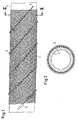
- the embodiment of the fluid line according to the invention 1 and 2 consists of a tube 1, a casing 2 surrounding the tube 1 in the form of a braid and a heat conductor woven into the braid Third
- the tube 1 is made of plastic, preferably thermoplastic Plastic, such as polyamide, can as well made of rubber or metal. It can also be one Be multi-layer pipe. In any case it is opposite Hydrocarbons, such as oil, impermeable. shown is a smooth pipe. It can also be wavy. Preferably, it is flexible.
- the sheath 2 is a fiber braid of plastic fibers, but it can also be made of glass, natural or mineral Metal fibers exist. It is loose on the pipe 2 arranged and is in the finished state of the fluid line free to the outside. Further, it is on the pipe 2 displaceable. It can therefore be retrofitted on the pipe arranged and moved to the desired location become.
- the shell 2 has a high strength, so that they pipe 1 from excessive expansion at high Internal pressure protects. In addition, the case is 2 abrasion. It therefore protects the pipe 1 against Abrasion. For repair purposes, it is easily replaceable.
- the tube 1 and the shell 2 are also recyclable.
- the heating conductor 3 is woven into the braid of the shell 2.
- the sheath 2 can also be formed as a fabric be, in which the heating element 3 is woven.
- He includes a heating wire 4, which is an elongated insulating material surrounds helically.
- the insulating material is a glass fiber bundle around which the heating wire 4 is wound is.
- the heating wire 4 and the glass fiber bundle surrounds a transparent, flexible plastic layer, which in turn is electrically insulating. Further is the heating element 3 in the shell 2 slidably.
- the helical shape of the heating wire 4 allows the use a resistance wire with low resistance per unit length. Due to the helical shape of the heating conductor 3, the heating power per unit area of the tube. 1 opposite a rectilinear arrangement of the heating conductor elevated.
- the displaceability of the heating element 3 in the Case 2 allows by axial compression of the Braid of the shell 2, the pushing out of end portions the heating conductor 3 from the shell 2, when the Ends of the heating element 3 during the cutting of a shell 2 forming section of a longer ("endless") Cover with the ends of the cut-off cover 2 are flush.
- the heating conductor 3 can be, if one end with one end of the shell 2 is flush and its other end sufficiently far from the other end of the shell 2 protrudes, in the shell 2 so be moved far, until the one end also off the shell 2 protrudes to provide a connection to be able to.
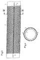
- FIGS. 3 and 4 differs only from the first embodiment in that the heating conductor 3 is not helical but is incorporated in a straight line in the shell 2 and instead of the one heat conductor, as in the first embodiment, two diametrically opposite ones Heating conductor 3 are provided, either in series or can be connected in parallel, so that the Fluid flow in the tube 1 heated from two sides becomes.
- the illustrated embodiments may be in many Be modified:
- the conductor can alternatively be a light or fluid conductor.
- the tube can serve as a carrier to the light guide do not have to disassemble and install separately when the light guide at least largely on the same Way how the pipe should be laid.
- As a fluid conductor he may be formed as a tube or hose, through which passed a warm heating fluid or a cooling fluid becomes.
- the shell may be at least one point on the pipe, after being pushed onto the pipe, fastened been an unintentional shift in the Prevent hull.
- the entire shell can be formed as a conductor be it as a heating, fluid or optical fiber. in this connection one comes with the same material for shell and Ladder out.
- the shell 1 can also be surrounded by a protective cover be. This may comprise thermoplastic and arranged around the envelope 1, splashed around or be extruded on them.
- the conductor in a groove in the outside be disposed of the tube, wherein a shell is omitted.
- the groove can be undercut, so that the conductor in the groove can be latched. That way the leader can be arranged in a defined position in the tube, without being able to get out of it by itself Groove releases.
- the groove can be helical or rectilinear be.
- the conductor in this case also be a heating, light or fluid conductor.
- the conductor 3 in the embodiments according to Figs. 1 to 4 almost only punctiform on those Can lie on the tube 1, where a few threads of the braid of the sheath 2 close together over him are carried away, as shown schematically in the drawings is indicated, the conductor 3 is in the embodiment 5 large-scale on the pipe 1, where he is under several adjacent fiber bundles the shell 2 is passed away. This results a better heat transfer between tube 1 and conductor 3, if this is a heating conductor or a coolant conductor.
Abstract
Description
Die Erfindung betrifft eine Fluidleitung mit einem Rohr, das eine Hülle aus einem Gewebe oder Geflecht aufweist, das seinerseits mindestens einen Leiter aufweist.The invention relates to a fluid line with a Pipe, which is a shell of a fabric or braid having, in turn, at least one conductor.
Eine derartige Fluidleitung wird häufig zum Beheizen eines Fluids in Kraftfahrzeugen eingesetzt, das bei tiefen Temperaturen gefriert oder zähflüssig wird.Such a fluid line is often used for heating a fluid used in motor vehicles, the freezes or becomes viscous at low temperatures.
So ist aus der DE 199 15 228 A1 eine gattungsgemäße beheizbare Fluidleitung für eine Kraftfahrzeug-Bremsvorrichtung bekannt, bei der auf einem inneren Rohr aus Gummi eine mittlere Gummischicht vorgesehen ist, in der ein die Hülle bildendes Verstärkungsgewebe eingebettet ist und die von einer radial äußeren Gummischicht umgeben ist. In das Verstärkungsgewebe ist ein elektrischer Heizleiter eingewebt oder eingeflochten. Die Herstellung dieser mehrschichtigen Fluidleitung ist aufwendig.Thus, from DE 199 15 228 A1 a generic heated Fluid line for a motor vehicle brake device known when looking at an inner tube Rubber is provided in the middle of a rubber layer a reinforcing fabric forming the shell is embedded is and surrounded by a radially outer rubber layer is. In the reinforcement fabric is an electrical Heat conductor woven or interwoven. The production This multilayer fluid line is expensive.
Der Erfindung liegt die Aufgabe zugrunde, eine Fluidleitung der eingangs genannten Art anzugeben, deren Aufbau einfacher ist.The invention is based on the object, a fluid line specify the type mentioned, whose Construction is easier.
Erfindungsgemäß besteht eine erste Lösung darin, daß die Hülle im fertigen Zustand der Fluidleitung das Rohr unmittelbar umgibt und jeder Leiter lose in der Hülle angeordnet ist.According to the invention, a first solution is that the shell in the finished state of the fluid line the pipe immediately surrounds and each conductor loose in the shell is arranged.
Bei dieser Lösung entfällt eine mittlere Gummischicht, in der die Hülle eingebettet ist, und das Einbetten des die Hülle bildenden Gewebes oder Geflechts in der mittleren Schicht. Das Rohr muß nicht, wie im bekannten Fall, aus Gummi bestehen, kann aber ebenfalls aus Gummi oder einem anderen Werkstoff bestehen, z.B. aus thermoplastischem Kunststoff oder Metall. Die Hülle kann mithin nach Fertigstellung des Rohres um dieses herum auf einfache Weise hergestellt werden. Gleichzeitig kann der Leiter in der Hülle eingewebt oder eingeflochten werden. Gegebenenfalls können die Hülle und der Leiter nachgerüstet werden. Bei hinreichender Festigkeit der Hülle kann sie ebenfalls zur Verstärkung oder zum Schutz des Rohres dienen. Wenn ein Ende des Leiters nach der Ausbildung der Hülle mit einem Ende der Hülle bündig abschließt, aber das andere Leiterende hinreichend weit aus dem anderen Ende der Hülse herausragt, kann der Leiter, da er lose in der Hülle angeordnet ist, auf einfache Weise an dem herausragenden Ende erfaßt und etwas aus der Hülse herausgeschoben werden, um beide Enden des Leiters mit Anschlüssen zu versehen oder, bei zwei Leitern, aus der Hülle herausragende bzw. herausgezogene Leiterenden zu verbinden, so daß sich ein Hin- und Rückleiter ergibt.This solution eliminates a medium rubber layer in which the shell is embedded, and the embedding of the the sheath forming tissue or braid in the middle Layer. The tube does not have, as in the known Case, made of rubber, but can also be made of rubber or another material, e.g. made of thermoplastic Plastic or metal. The shell can therefore after completion of the tube around this on easy way to be made. At the same time the conductor woven or braided in the envelope become. Optionally, the shell and the conductor be retrofitted. With sufficient strength of Sheath can also be used for reinforcement or for Serve protection of the pipe. If one end of the conductor after forming the sleeve with one end of the sleeve flush, but sufficient enough for the other leader protruding far from the other end of the sleeve, may be the conductor, since it is loosely arranged in the shell is detected in a simple manner at the outstanding end and something out of the sleeve to be pushed out to provide both ends of the conductor with connections or, in the case of two ladders, protruding from the casing or pulled out conductor ends to connect, so that there is a return conductor.
Ferner kann die Hülle das Rohr nach außen freiliegend umgeben. Gegebenenfalls entfällt eine äußere Gummischicht.Further, the sheath may expose the tube to the outside surround. Optionally eliminates an outer rubber layer.
Eine andere Lösung der genannten Aufgabe besteht erfindungsgemäß darin, daß jeder Leiter die Hülle bildet.Another solution to the above problem is inventively in that each conductor forms the envelope.
Bei dieser Lösung entfällt die separate Ausbildung von Hülle und Leiter, da der Leiter selbst die Hülle beziehungsweise das Gewebe oder Geflecht bildet.This solution eliminates the separate training of Sheath and conductor, since the conductor itself or the shell the tissue or braid forms.
Vorzugsweise ist jeder Leiter ein Heiz- oder Lichtleiter. Mittels des Heizleiters kann das Fluid in dem Rohr erwärmt werden. Bei Ausbildung des Leiters als Lichtleiter kann das Rohr als Träger des Leiters dienen, zum Beispiel in einem Kraftfahrzeug, so daß eine separate Verlegung oder Montage des Lichtleiters entfällt.Preferably, each conductor is a heating or light guide. By means of the heating element, the fluid in the tube to be heated. In training of the conductor as a light guide the pipe can serve as a carrier of the conductor, for Example in a motor vehicle, so that a separate Installation or assembly of the light guide is no longer necessary.
Der Heizleiter kann ein elektrischer Heizdraht oder ein Fluidleiter für ein warmes Heizfluid sein. Zwar wäre auch eine Litze als Heizleiter anwendbar, ein einzelner Heizdraht läßt sich jedoch leichter bei der Herstellung des Gewebes oder Geflechts in dieses aufnehmen. Ein Fluidleiter, z.B. ein dünner Schlauch aus einem Elastomer, kann mit Vorteil dann eingesetzt werden, wenn ein warmes Heizfluid verfügbar ist, z.B. das erwärmte Kühlwasser in einem Kraftfahrzeug. Auch erwärmte Luft oder ein heißes Abgas wäre geeignet. In anderen Anwendungsfällen könnte auch Dampf verwendet werden. The heating conductor can be an electric heating wire or a Be fluid conductor for a warm heating fluid. Although it would be also a strand as heat conductor applicable, a single Heating wire, however, is easier to manufacture of the tissue or braid. One Fluid conduit, e.g. a thin tube made of an elastomer, can be used with advantage then, if one warm heating fluid is available, e.g. the heated cooling water in a motor vehicle. Also heated air or a hot exhaust gas would be suitable. In other applications Steam could also be used.
In Fällen, in denen das Fluid in dem Rohr gekühlt werden müßte, kann der Leiter ein Kühlmittelleiter sein.In cases where the fluid in the tube is cooled If necessary, the conductor may be a coolant conductor.
Ferner kann dafür gesorgt sein, daß jeder Heizleiter oder Kühlmittelleiter durch das Material der Hülle hindurch stellenweise am Rohr anliegt. Dies ergibt eine bessere Wärmeübertragung zwischen Rohr und Heizleiter bzw. Kühlmittelleiter.Furthermore, it can be ensured that each heating conductor or coolant through the material of the shell in places rests on the pipe. This gives a better heat transfer between tube and heat conductor or coolant pipe.
Als Lichtleiter ist eine Glas- oder Kunststoff-Faser besonders geeignet. Beide können biegsam ausgebildet sein, um den Lichtleiter auch auf gekrümmten Wegen zu verlegen.As a light guide is a glass or plastic fiber particularly suitable. Both can be made flexible be to the optical fiber also on curved paths embarrassed.
Ferner kann die gesamte Hülle aus Glas-, Kunststoff-, Natur-, Kohlenstoff-, Mineral- oder Metallfasern bestehen. Aus solchen Fasern läßt sich das Geflecht oder Gewebe leicht herstellen.Furthermore, the entire shell of glass, plastic, Natural, carbon, mineral or metal fibers exist. From such fibers, the braid or tissue can be easy to make.
Sodann kann jeder Leiter in dem Gewebe oder Geflecht geradlinig oder gewunden angeordnet sein. Insbesondere kann jeder Leiter wendelförmig um das Rohr herumgewikkelt sein.Then every conductor in the fabric or braid be arranged in a straight line or wound. Especially Each conductor can be wound helically around the pipe be.
Ferner kann jeder Heizdraht in Isoliermaterial angeordnet sein. Vorzugsweise ist er dann in langgestrecktem Isoliermaterial wendelförmig angeordnet. Dabei kann das Isoliermaterial ein Glasfaserbündel, um das jeder Heizdraht herumgewickelt ist, und eine den Heizdraht und das Glasfaserbündel umgebende, flexible Kunststoffschicht aufweisen. Ein derartiger Heizleiter ist insgesamt sehr flexibel und kann daher beim Verlegen oder Einflechten oder Einweben nahezu beliebig gebogen werden.Furthermore, each heating wire can be arranged in insulating material be. Preferably, it is then in elongated Insulating arranged helically. It can do that Insulating a fiber-optic bundle around each one Heating wire is wound around, and a heating wire and the fiberglass bundle surrounding, flexible plastic layer exhibit. Such a heating element is a total very flexible and can therefore when laying or Braiding or weaving are bent almost arbitrarily.
Das Rohr kann glatt oder gewellt sein, wobei die Hülle lose auf dem Rohr angeordnet sein kann. Sie läßt sich dann, auch bei einem gewellten Rohr, leicht auf dem Rohr bis zu der gewünschten Position verschieben, insbesondere, wenn sie nachgerüstet wird.The tube may be smooth or wavy, with the sheath can be arranged loosely on the tube. She lets herself then, even with a corrugated pipe, light on the Move the tube to the desired position, in particular, if it is retrofitted.
Ferner kann jeder Leiter in der Hülle in deren Längsrichtung verschiebbar sein. Er ist dann durch Zusammenstauchen der Hülle an seinen Enden leicht zugänglich, um ihn mit einer Strom-, oder Fluid- oder Lichtquelle zu verbinden. Ferner kann das Rohr durch das Zusammenstauchen der Hülle an seinen Enden vorübergehend zum Festklemmen des Rohres beim Einführen eines Steckverbinders in das Rohrende freigelegt werden.Furthermore, each conductor in the shell in the longitudinal direction be displaceable. He is then by diving together the cover easily accessible at its ends, to him with a power, or fluid or light source connect to. Furthermore, the tube can by upsetting the sheath at its ends temporarily to Clamp the tube when inserting a connector be exposed in the pipe end.
Alternativ zu einer völlig losen Anordnung der Hülle auf dem Rohr kann sie an mindestens einer Stelle auf dem Rohr befestigt sein. Sie ist dann nachträglich nicht mehr verschiebbar.Alternatively to a completely loose arrangement of the shell on the pipe she can at least one place on be attached to the pipe. It is then subsequently no longer movable.
Statt die Hülle außen frei zu lassen, kann sie auch von einer Schutzhülle umgeben sein, die thermoplastischen Kunststoff aufweist und um die erstgenannte Hülle herum angeordnet, herumgespritzt oder auf sie aufextrudiert wird. Auch hierbei kann zunächst ein Teil des Leiters seitlich aus der erstgenannten Hülle herausgezogen und die erstgenannte Hülle auf die gewünschte Länge zugeschnitten werden, bevor die Schutzhülle aufgebracht wird, so daß der Leiter nach dem Aufbringen der Schutzhülle freiliegt und mit Anschlüssen versehen werden kann, oder bei zwei Leitern, deren Enden verbunden werden können, um einen Hin- und Rückleiter zu bilden.Instead of leaving the shell outside, it can also be used by be surrounded by a protective cover, the thermoplastic Plastic and around the former shell around arranged, splashed or extruded onto them becomes. Again, this may be a part of the head first pulled out laterally from the former shell and the former shell cut to the desired length be applied before the protective cover so that the conductor after applying the protective cover exposed and provided with connections can, or two conductors whose ends are connected can to form a forward and return conductor.
Alternativ kann bei einer Fluidleitung mit einem Rohr aus biegsamem Material, in dem ein Leiter angeordnet ist, durch den ein Strom zur Änderung der Temperatur des Fluids in der Fluidleitung hindurchleitbar ist, der Leiter in einer Nut in der Außenseite des Rohres angeordnet sein. Hierbei kommt man ohne die Hülle aus.Alternatively, in a fluid line with a pipe made of flexible material in which a ladder is arranged is through which a current to change the temperature of the fluid in the fluid conduit is passable, the Ladder arranged in a groove in the outside of the pipe be. Here you get out without the shell.
Die Nut kann hinterschnitten sein, so daß der Leiter in die Nut einrastbar ist. Sie löst sich dann nicht ohne weiteres von selbst von dem Rohr.The groove can be undercut, so that the conductor in the groove can be latched. It does not dissolve then without more by itself from the pipe.
Auch in diesem Falle kann der Leiter ein elektrischer Leiter, ein Fluidleiter oder ein Lichtleiter sein, wie sie zuvor geschildert wurden.Also in this case, the conductor can be an electrical Be conductor, a fluid conductor or a light guide, such as they were described before.
Die Erfindung und ihre Weiterbildungen werden nachstehend anhand der beiliegenden Zeichnungen bevorzugter Ausführungsbeispiele näher beschrieben. Darin stellen dar:
- Fig. 1
- eine Seitenansicht eines ersten Ausführungsbeispiel einer erfindungsgemäßen Fluidleitung,
- Fig. 2
- den Schnitt II-II der Fig. 1,
- Fig. 3
- eine Seitenansicht eines zweiten Ausführungsbeispiels einer erfindungsgemäßen Fluidleitung,
- Fig. 4
- den Schnitt IV-IV der Fig. 3 und
- Fig. 5
- eine Seitenansicht eines dritten Ausführungsbeispiels einer erfindungsgemäßen Fluidleitung.
- Fig. 1
- a side view of a first embodiment of a fluid conduit according to the invention,
- Fig. 2
- the section II-II of Fig. 1,
- Fig. 3
- a side view of a second embodiment of a fluid conduit according to the invention,
- Fig. 4
- the section IV-IV of Fig. 3 and
- Fig. 5
- a side view of a third embodiment of a fluid conduit according to the invention.
Das Ausführungsbeispiel der erfindungsgemäßen Fluidleitung
nach den Fig. 1 und 2 besteht aus einem Rohr 1,
einer das Rohr 1 umgebenden Hülle 2 in Form eines Geflechts
und einem in das Geflecht eingeflochtenen Heizleiter
3.The embodiment of the fluid line according to the
Das Rohr 1 besteht aus Kunststoff, vorzugsweise thermoplastischem Kunststoff, wie Polyamid, kann aber auch aus Gummi oder Metall bestehen. Es kann aber auch ein Mehrschichtrohr sein. In jedem Fall ist es gegenüber Kohlenwasserstoffen, wie Öl, impermeabel. Dargestellt ist ein glattes Rohr. Es kann aber auch gewellt sein. Vorzugsweise ist es biegsam.The tube 1 is made of plastic, preferably thermoplastic Plastic, such as polyamide, can as well made of rubber or metal. It can also be one Be multi-layer pipe. In any case it is opposite Hydrocarbons, such as oil, impermeable. shown is a smooth pipe. It can also be wavy. Preferably, it is flexible.
Die Hülle 2 ist ein Fasergeflecht aus Kunststoff-Fasern,
sie kann aber auch aus Glas-, Natur-, Mineraloder
Metallfasern bestehen. Sie ist lose auf dem Rohr 2
angeordnet und liegt im fertigen Zustand der Fluidleitung
nach außen frei. Ferner ist sie auf dem Rohr 2
verschiebbar. Sie kann daher nachträglich auf dem Rohr
angeordnet und bis zu der gewünschten Stelle verschoben
werden. Die Hülle 2 hat eine hohe Festigkeit, so daß
sie das Rohr 1 vor einer übermäßigen Aufweitung bei hohem
Innendruck schützt. Darüber hinaus ist die Hülle 2
scheuerfest. Sie schützt daher das Rohr 1 auch gegen
Abrieb. Für Reparaturzwecke ist sie leicht auswechselbar.
Das Rohr 1 und die Hülle 2 sind außerdem recyclebar.The
Der Heizleiter 3 ist in das Geflecht der Hülle 2 eingeflochten.
Die Hülle 2 kann aber auch als Gewebe ausgebildet
sein, in dem der Heizleiter 3 eingewebt ist. Er
enthält einen Heizdraht 4, der ein langgestrecktes Isoliermaterial
wendelförmig umgibt. Das Isoliermaterial
ist ein Glasfaserbündel, um das der Heizdraht 4 herumgewickelt
ist. Den Heizdraht 4 und das Glasfaserbündel
umgibt eine durchsichtige, flexible Kunststoffschicht,
die ihrerseits elektrisch isolierend ist. Ferner ist
der Heizleiter 3 in der Hülle 2 verschiebbar.The heating conductor 3 is woven into the braid of the
Die Wendelform des Heizdrahtes 4 ermöglicht die Verwendung
eines Widerstandsdrahtes mit geringem Widerstand
pro Längeneinheit. Durch die Wendelform des Heizleiters
3 wird die Heizleistung pro Flächeneinheit des Rohres 1
gegenüber einer geradlinigen Anordnung des Heizleiters
erhöht. Die Verschiebbarkeit des Heizleiters 3 in der
Hülle 2 ermöglicht durch axiales Zusammendrücken des
Geflechts der Hülle 2 das Herausschieben von Endabschnitten
des Heizleiters 3 aus der Hülle 2, wenn die
Enden des Heizleiters 3 beim Abschneiden eines die Hülle
2 bildenden Abschnitts von einer längeren ("endlosen")
Hülle mit den Enden der abgeschnittenen Hülle 2
bündig sind. Die nach dem Zusammendrücken der Hülle 2
an ihren Enden herausragenden Abschnitte des Heizleiters
3 können dann abisoliert und der Heizdraht 4 mit
einem Anschluß, wie dem schematisch dargestellten Anschlußstecker
5 oder einer Anschlußklemme, versehen
werden, um den Heizleiter 3 mit einer Stromquelle zu
verbinden. Umgekehrt kann der Heizleiter 3, wenn sein
eines Ende mit dem einen Ende der Hülle 2 bündig abschließt
und sein anderes Ende hinreichend weit aus dem
anderen Ende der Hülle 2 herausragt, in der Hülle 2 so
weit verschoben werden, bis das eine Ende ebenfalls aus
der Hülle 2 herausragt, um mit einem Anschluß versehen
werden zu können.The helical shape of the heating wire 4 allows the use
a resistance wire with low resistance
per unit length. Due to the helical shape of the heating conductor
3, the heating power per unit area of the tube. 1
opposite a rectilinear arrangement of the heating conductor
elevated. The displaceability of the heating element 3 in the
Das Ausführungsbeispiel nach den Fig. 3 und 4 unterscheidet
sich von dem ersten Ausführungsbeispiel nur
dadurch, daß der Heizleiter 3 nicht wendelförmig, sondern
geradlinig in der Hülle 2 eingearbeitet ist und
statt des einen Heizleiters, wie bei dem ersten Ausführungsbeispiel,
zwei sich diametral gegenüberliegende
Heizleiter 3 vorgesehen sind, die entweder in Reihe
oder parallelgeschaltet werden können, so daß die
Fluidströmung in dem Rohr 1 von zwei Seiten beheizt
wird.The embodiment of FIGS. 3 and 4 differs
only from the first embodiment
in that the heating conductor 3 is not helical but
is incorporated in a straight line in the
Die dargestellten Ausführungsbeispiele können in vieler Hinsicht abgewandelt werden: Der Leiter kann alternativ ein Licht- oder Fluidleiter sein. Bei einem Lichtleiter kann das Rohr als Träger dienen, um den Lichtleiter nicht getrennt montieren und verlegen zu müssen, wenn der Lichtleiter zumindest weitgehend auf dem gleichen Weg wie das Rohr verlegt werden müßte. Als Fluidleiter kann er als Rohr oder Schlauch ausgebildet sein, durch den ein warmes Heizfluid oder ein Kühlfluid geleitet wird.The illustrated embodiments may be in many Be modified: The conductor can alternatively be a light or fluid conductor. With a light guide The tube can serve as a carrier to the light guide do not have to disassemble and install separately when the light guide at least largely on the same Way how the pipe should be laid. As a fluid conductor he may be formed as a tube or hose, through which passed a warm heating fluid or a cooling fluid becomes.
Die Hülle kann an mindestens einer Stelle auf dem Rohr, nachdem sie auf das Rohr geschoben wurde, befestigt worden sein, um eine unbeabsichtigte Verschiebung der Hülle zu verhindern. The shell may be at least one point on the pipe, after being pushed onto the pipe, fastened been an unintentional shift in the Prevent hull.
Ferner kann die gesamte Hülle als Leiter ausgebildet sein, sei es als Heiz-, Fluid- oder Lichtleiter. Hierbei kommt man mit dem gleichen Material für Hülle und Leiter aus.Furthermore, the entire shell can be formed as a conductor be it as a heating, fluid or optical fiber. in this connection one comes with the same material for shell and Ladder out.
Die Hülle 1 kann auch mit einer Schutzhülle umgeben sein. Diese kann thermoplastischen Kunststoff aufweisen und um die Hülle 1 herum angeordnet, herumgespritzt oder auf sie aufextrudiert sein.The shell 1 can also be surrounded by a protective cover be. This may comprise thermoplastic and arranged around the envelope 1, splashed around or be extruded on them.
Sodann kann der Leiter in einer Nut in der Außenseite des Rohres angeordnet sein, wobei eine Hülle entfällt. Die Nut kann hinterschnitten sein, so daß der Leiter in die Nut einrastbar ist. Auf diese Weise kann der Leiter in einer definierten Lage in dem Rohr angeordnet werden, ohne daß er sich ohne weiteres von selbst aus der Nut löst. Hierbei kann die Nut wendelförmig oder geradlinig sein. Ferner kann der Leiter in diesem Fall ebenfalls ein Heiz-, Licht- oder Fluidleiter sein.Then, the conductor in a groove in the outside be disposed of the tube, wherein a shell is omitted. The groove can be undercut, so that the conductor in the groove can be latched. That way the leader can be arranged in a defined position in the tube, without being able to get out of it by itself Groove releases. Here, the groove can be helical or rectilinear be. Furthermore, the conductor in this case also be a heating, light or fluid conductor.
Während der Leiter 3 bei den Ausführungsbeispielen nach
den Fig. 1 bis 4 nahezu nur punktförmig an denjenigen
Stellen am Rohr 1 anliegen kann, an denen wenige Fäden
des Geflechts der Hülle 2 dicht nebeneinander über ihn
hinweggeführt sind, wie es schematisch in den Zeichnungen
angedeutet ist, liegt der Leiter 3 bei dem Ausführungsbeispiel
nach Fig. 5 großflächiger am Rohr 1 an,
wo er unter mehreren nebeneinanderliegenden Faserbündeln
der Hülle 2 hinweggeführt ist. Dadurch ergibt sich
eine bessere Wärmeübertragung zwischen Rohr 1 und Leiter
3, wenn es sich bei diesem um einen Heizleiter oder
einen Kühlmittelleiter handelt.While the conductor 3 in the embodiments according to
Figs. 1 to 4 almost only punctiform on those
Can lie on the tube 1, where a few threads
of the braid of the
Claims (25)
Applications Claiming Priority (4)
| Application Number | Priority Date | Filing Date | Title |
|---|---|---|---|
| DE10349418 | 2003-10-21 | ||
| DE10349418 | 2003-10-21 | ||
| DE102004001887A DE102004001887A1 (en) | 2003-10-21 | 2004-01-14 | fluid line |
| DE102004001887 | 2004-01-14 |
Publications (2)
| Publication Number | Publication Date |
|---|---|
| EP1526322A1 true EP1526322A1 (en) | 2005-04-27 |
| EP1526322B1 EP1526322B1 (en) | 2007-11-07 |
Family
ID=34395068
Family Applications (1)
| Application Number | Title | Priority Date | Filing Date |
|---|---|---|---|
| EP04022000A Active EP1526322B1 (en) | 2003-10-21 | 2004-09-16 | Fluid conduit |
Country Status (6)
| Country | Link |
|---|---|
| US (2) | US7190892B2 (en) |
| EP (1) | EP1526322B1 (en) |
| JP (1) | JP2005127516A (en) |
| CA (1) | CA2483730A1 (en) |
| DE (1) | DE502004005422D1 (en) |
| ES (1) | ES2291791T3 (en) |
Cited By (2)
| Publication number | Priority date | Publication date | Assignee | Title |
|---|---|---|---|---|
| EP1764541A1 (en) | 2005-09-20 | 2007-03-21 | DBK David + Baader GmbH | Electric heating device, heatable hose and its manufacturing method |
| NL2006464C2 (en) * | 2011-03-24 | 2012-09-25 | Tr Buchet B V | TUBE MANUFACTURED FROM THERMOVABLE FIBERS. |
Families Citing this family (29)
| Publication number | Priority date | Publication date | Assignee | Title |
|---|---|---|---|---|
| IT1319652B1 (en) * | 2000-11-15 | 2003-10-23 | Thermoquest Italia Spa | COLUMN FOR CHROMATOGRAPHY. |
| FR2874075B1 (en) * | 2004-08-03 | 2007-11-09 | Espa Sarl | FLUID TRANSPORT TUBE |
| JP2006336886A (en) * | 2005-05-31 | 2006-12-14 | Nippon Oil Corp | Combination heater and heating system comprising the same |
| US7606475B2 (en) * | 2005-06-10 | 2009-10-20 | Steve Novotny | Heat generation system |
| DE102005048943A1 (en) * | 2005-10-13 | 2007-04-19 | Phoenix Fluid Handling Industry Gmbh | Heated hose |
| US20070212037A1 (en) * | 2006-03-03 | 2007-09-13 | Andreas Koenekamp | Heating element and mounting for media piping of fuel cell systems |
| US20080298788A1 (en) * | 2007-06-04 | 2008-12-04 | Teleflex Fluid Systems, Inc. | Heated hose apparatus and method |
| JP4987600B2 (en) * | 2007-07-20 | 2012-07-25 | 三桜工業株式会社 | Resin tube |
| JP2011501052A (en) * | 2007-10-11 | 2011-01-06 | タイコ・サーマル・コントロルズ・エルエルシー | Flexible heated hose and manufacturing method thereof |
| DE102008032509A1 (en) * | 2008-07-10 | 2010-01-14 | Epcos Ag | Heating device and method for producing the heating device |
| US8322574B1 (en) * | 2008-08-01 | 2012-12-04 | Phillips Larry K | Drinking water dispensing system for automobiles and associated method |
| US8559800B2 (en) * | 2009-02-13 | 2013-10-15 | The Gates Corporation | Heated fluid conduit end covers, systems and methods |
| DE202009003807U1 (en) * | 2009-03-20 | 2010-08-12 | Voss Automotive Gmbh | Electric heating system for a fluid line system |
| DE202010007821U1 (en) * | 2010-06-10 | 2011-09-02 | Viessmann Werke Gmbh & Co Kg | Vacuum sorption |
| ITTO20100773A1 (en) * | 2010-09-22 | 2012-03-23 | Dytech Dynamic Fluid Tech Spa | PIPE FOR A SCR CIRCUIT OF A VEHICLE |
| DE102010061271A1 (en) * | 2010-12-15 | 2012-06-21 | Contitech Schlauch Gmbh | Heatable connection device for media-carrying, electrically heatable hoses |
| NO334353B1 (en) * | 2011-02-24 | 2014-02-17 | Nexans | Low voltage direct electric heating for flexible pipes / risers |
| US9435477B2 (en) * | 2011-03-22 | 2016-09-06 | Sami Mustafa | Creating thermal uniformity in heated piping and weldment systems |
| US8100315B1 (en) * | 2011-07-11 | 2012-01-24 | Tennco Automotive Operating Company Inc. | Method of insulating an exhaust device |
| DE102011120357A1 (en) * | 2011-12-07 | 2013-06-13 | Voss Automotive Gmbh | Prefabricated heatable media line with a media line with at least two arranged on the outside heating elements and method for their preparation |
| WO2014138742A1 (en) | 2013-03-08 | 2014-09-12 | Federal-Mogul Powertrain, Inc. | Wrappable textile sleeve with extendable electro-functional yarn leads and method of contruction thereof |
| JP6453843B2 (en) | 2013-03-13 | 2019-01-16 | フェデラル−モーグル・パワートレイン・リミテッド・ライアビリティ・カンパニーFederal−Mogul Powertrain Llc | Wrapping sleeve with warp knitting with extendable electrical function yarn and method of construction |
| US9488201B2 (en) * | 2014-10-03 | 2016-11-08 | Adel Wiggins Group, a Division of TransDigm Inc. | Tucked cushion clamp and process of making a tucked cushion clamp |
| US20160348943A1 (en) * | 2015-05-29 | 2016-12-01 | Eiko Electric Products Corp. | Water inlet/outlet reversible water heater |
| DE202016100917U1 (en) * | 2016-02-22 | 2016-03-09 | Türk & Hillinger GmbH | Air and / or aerosol heater |
| EP3279541A1 (en) * | 2016-08-03 | 2018-02-07 | LEONI Kabel Holding GmbH | Heatable media guidance and method of manufacturing same |
| US10396500B2 (en) | 2016-08-31 | 2019-08-27 | Norma U.S. Holding Llc | Electrically conductive conduit assembly |
| GB201718752D0 (en) * | 2017-11-13 | 2017-12-27 | Edwards Ltd | Vacuum and abatement systems |
| KR102113399B1 (en) * | 2018-10-01 | 2020-05-20 | 한국해양대학교 산학협력단 | Helical Trace Heating Flowline |
Citations (13)
| Publication number | Priority date | Publication date | Assignee | Title |
|---|---|---|---|---|
| US2003586A (en) * | 1931-12-28 | 1935-06-04 | Laval Separator Co De | Milking machine connecter and pneumatic and electric conductor therefor |
| GB1160805A (en) * | 1967-07-08 | 1969-08-06 | Engl Ltd J | Improvements in or relating to Flexible Conduits |
| DE1775094A1 (en) * | 1968-07-05 | 1971-05-19 | Pforzheim Metallschlauch | Gas hose-electrically conductive |
| US3623337A (en) * | 1968-08-07 | 1971-11-30 | Harry H Tremont | Apparatus for freezing liquid in a section of a pipe |
| US3780208A (en) * | 1972-06-05 | 1973-12-18 | Moore & Co Samuel | Composite hose having a grounding wire enclosed in a sleeve and wrapped about the core tube of the hose |
| US4133972A (en) * | 1976-01-26 | 1979-01-09 | Aktiebolaget Electrolux | Vacuum cleaner hose having an electrical conductor |
| EP0142624A2 (en) * | 1983-09-09 | 1985-05-29 | Continental Aktiengesellschaft | Tube |
| GB2197419A (en) * | 1986-09-25 | 1988-05-18 | Raychem Gmbh | Conduit with heater strip |
| DE4230795A1 (en) * | 1992-09-15 | 1994-03-17 | Vortex Gmbh Dt | Hot water pipe between e.g. boiler and end equipment - provides support surface for electric heating band extending along length of hot water line |
| WO1996011356A1 (en) * | 1994-10-05 | 1996-04-18 | Exxon Chemical Patents Inc. | Hot melt flexible hose with replaceable core |
| DE19915228A1 (en) | 1999-04-03 | 2000-10-05 | Continental Teves Ag & Co Ohg | Flexible pressure tubing with heater, for modulated, pump-assisted vehicle braking system, avoids reduced braking efficiency caused by low temperatures, whilst being simple, durable, light, flexible and easily-manufactured |
| DE20114231U1 (en) * | 2001-08-29 | 2001-11-29 | Leoni Protec Cable Systems Gmb | Industrial robots |
| US20030007789A1 (en) * | 2001-07-03 | 2003-01-09 | Nordson Corporation | Insulated hose for transmitting hot liquids |
Family Cites Families (5)
| Publication number | Priority date | Publication date | Assignee | Title |
|---|---|---|---|---|
| US3603403A (en) * | 1969-08-20 | 1971-09-07 | Lewis Eng Co | Automatic fire extinguishing apparatus |
| FR2226799A1 (en) | 1973-04-18 | 1974-11-15 | Fressynet Et Fils Ets A | Heating sheath in electrical circuits - uses braiding technique and allows choice of heating range |
| US4352007A (en) * | 1980-10-22 | 1982-09-28 | Nordson Corporation | Hot melt multi-section hose heating system |
| US4553023A (en) * | 1981-11-27 | 1985-11-12 | Nordson Corporation | Thermally insulated electrically heated hose for transmitting hot liquids |
| DE3346191A1 (en) | 1983-12-21 | 1985-07-04 | Phoenix Ag, 2100 Hamburg | Hose with incorporated electrical heating and control device |
-
2004
- 2004-09-16 DE DE502004005422T patent/DE502004005422D1/en active Active
- 2004-09-16 EP EP04022000A patent/EP1526322B1/en active Active
- 2004-09-16 ES ES04022000T patent/ES2291791T3/en active Active
- 2004-09-22 US US10/947,044 patent/US7190892B2/en active Active
- 2004-10-04 CA CA002483730A patent/CA2483730A1/en not_active Abandoned
- 2004-10-20 JP JP2004305376A patent/JP2005127516A/en active Pending
-
2006
- 2006-04-11 US US11/402,067 patent/US7687745B2/en active Active
Patent Citations (13)
| Publication number | Priority date | Publication date | Assignee | Title |
|---|---|---|---|---|
| US2003586A (en) * | 1931-12-28 | 1935-06-04 | Laval Separator Co De | Milking machine connecter and pneumatic and electric conductor therefor |
| GB1160805A (en) * | 1967-07-08 | 1969-08-06 | Engl Ltd J | Improvements in or relating to Flexible Conduits |
| DE1775094A1 (en) * | 1968-07-05 | 1971-05-19 | Pforzheim Metallschlauch | Gas hose-electrically conductive |
| US3623337A (en) * | 1968-08-07 | 1971-11-30 | Harry H Tremont | Apparatus for freezing liquid in a section of a pipe |
| US3780208A (en) * | 1972-06-05 | 1973-12-18 | Moore & Co Samuel | Composite hose having a grounding wire enclosed in a sleeve and wrapped about the core tube of the hose |
| US4133972A (en) * | 1976-01-26 | 1979-01-09 | Aktiebolaget Electrolux | Vacuum cleaner hose having an electrical conductor |
| EP0142624A2 (en) * | 1983-09-09 | 1985-05-29 | Continental Aktiengesellschaft | Tube |
| GB2197419A (en) * | 1986-09-25 | 1988-05-18 | Raychem Gmbh | Conduit with heater strip |
| DE4230795A1 (en) * | 1992-09-15 | 1994-03-17 | Vortex Gmbh Dt | Hot water pipe between e.g. boiler and end equipment - provides support surface for electric heating band extending along length of hot water line |
| WO1996011356A1 (en) * | 1994-10-05 | 1996-04-18 | Exxon Chemical Patents Inc. | Hot melt flexible hose with replaceable core |
| DE19915228A1 (en) | 1999-04-03 | 2000-10-05 | Continental Teves Ag & Co Ohg | Flexible pressure tubing with heater, for modulated, pump-assisted vehicle braking system, avoids reduced braking efficiency caused by low temperatures, whilst being simple, durable, light, flexible and easily-manufactured |
| US20030007789A1 (en) * | 2001-07-03 | 2003-01-09 | Nordson Corporation | Insulated hose for transmitting hot liquids |
| DE20114231U1 (en) * | 2001-08-29 | 2001-11-29 | Leoni Protec Cable Systems Gmb | Industrial robots |
Cited By (2)
| Publication number | Priority date | Publication date | Assignee | Title |
|---|---|---|---|---|
| EP1764541A1 (en) | 2005-09-20 | 2007-03-21 | DBK David + Baader GmbH | Electric heating device, heatable hose and its manufacturing method |
| NL2006464C2 (en) * | 2011-03-24 | 2012-09-25 | Tr Buchet B V | TUBE MANUFACTURED FROM THERMOVABLE FIBERS. |
Also Published As
| Publication number | Publication date |
|---|---|
| JP2005127516A (en) | 2005-05-19 |
| US20060193613A1 (en) | 2006-08-31 |
| US7190892B2 (en) | 2007-03-13 |
| DE502004005422D1 (en) | 2007-12-20 |
| US7687745B2 (en) | 2010-03-30 |
| EP1526322B1 (en) | 2007-11-07 |
| ES2291791T3 (en) | 2008-03-01 |
| CA2483730A1 (en) | 2005-04-21 |
| US20050084255A1 (en) | 2005-04-21 |
Similar Documents
| Publication | Publication Date | Title |
|---|---|---|
| EP1526322A1 (en) | Fluid conduit | |
| EP2596274B1 (en) | Heatable fluid line and method for its production | |
| DE10201920B4 (en) | Method for connecting a heating conductor of a flexible multilayered hose with an electrical connection device | |
| EP0499089B1 (en) | Flexible protection hose for oblong objects | |
| EP3882929B1 (en) | Coolable individual line and charging cable | |
| DE102007056169A1 (en) | Cylindrical heating element for e.g. medical hose for tempering blood in medical fluid line, has heating wire arranged helically around flexible interior material, and core material arranged in radial distance to heating wire | |
| EP2788692B1 (en) | Assembled heatable media line comprising a media line having at least two heating elements arranged on the exterior thereof, and method for the production thereof | |
| EP2788646B2 (en) | Assembled media line and method for assembling a media line comprising inner heating elements | |
| DE102004001887A1 (en) | fluid line | |
| EP1451497B1 (en) | Plastic tube, especially a pneumatic tube | |
| DE102012002411A1 (en) | Heatable medium spacer for use in vehicle e.g. lorry, has heating element with strands constantly extended along medium spacer part and spacer connector, and fastening unit for attaching strands to media spacer part or insulation device | |
| DE4100274C2 (en) | Process for producing an elongated profile part | |
| DE2042183A1 (en) | Flexible flow medium line | |
| DE4413578B4 (en) | feed | |
| EP1277261B1 (en) | Thermal insulation device, in particular for elongated bodies | |
| DE10020739A1 (en) | Surgical instrument visible in X-ray viewer, comprises elongate element which is provided with at least one strip shaped helically wound section containing or consisting of X-ray contrast material | |
| EP3234434B1 (en) | Heatable media line and method for producing a heatable media line | |
| WO2013026560A1 (en) | Tube and method for the production thereof | |
| DE19611586A1 (en) | Process for the production of a protective cable cover and plastic film for carrying out the process | |
| DE10036059B4 (en) | Electric heating tape | |
| DE10051111A1 (en) | Thermally insulated flexible conduit comprises a thermal insulation layer which surrounds the pipe and additionally embeds at least one elongate member | |
| EP3612759A1 (en) | Line assembly | |
| DE10311032B4 (en) | Cable and method of making a cable | |
| EP1378778A1 (en) | Protection hose of an optical fiber cable for laser applications | |
| WO2017167452A2 (en) | Pre-fabricated heatable media line and pre-fabricated heating element for use in same |
Legal Events
| Date | Code | Title | Description |
|---|---|---|---|
| PUAI | Public reference made under article 153(3) epc to a published international application that has entered the european phase |
Free format text: ORIGINAL CODE: 0009012 |
|
| AK | Designated contracting states |
Kind code of ref document: A1 Designated state(s): AT BE BG CH CY CZ DE DK EE ES FI FR GB GR HU IE IT LI LU MC NL PL PT RO SE SI SK TR |
|
| AX | Request for extension of the european patent |
Extension state: AL HR LT LV MK |
|
| 17P | Request for examination filed |
Effective date: 20050707 |
|
| AKX | Designation fees paid |
Designated state(s): DE ES FR GB IT SE |
|
| GRAP | Despatch of communication of intention to grant a patent |
Free format text: ORIGINAL CODE: EPIDOSNIGR1 |
|
| RAP1 | Party data changed (applicant data changed or rights of an application transferred) |
Owner name: NORMA GERMANY GMBH |
|
| GRAS | Grant fee paid |
Free format text: ORIGINAL CODE: EPIDOSNIGR3 |
|
| GRAA | (expected) grant |
Free format text: ORIGINAL CODE: 0009210 |
|
| AK | Designated contracting states |
Kind code of ref document: B1 Designated state(s): DE ES FR GB IT SE |
|
| REG | Reference to a national code |
Ref country code: GB Ref legal event code: FG4D Free format text: NOT ENGLISH |
|
| REG | Reference to a national code |
Ref country code: SE Ref legal event code: TRGR |
|
| GBT | Gb: translation of ep patent filed (gb section 77(6)(a)/1977) |
Effective date: 20071121 |
|
| REF | Corresponds to: |
Ref document number: 502004005422 Country of ref document: DE Date of ref document: 20071220 Kind code of ref document: P |
|
| REG | Reference to a national code |
Ref country code: ES Ref legal event code: FG2A Ref document number: 2291791 Country of ref document: ES Kind code of ref document: T3 |
|
| ET | Fr: translation filed | ||
| PLBE | No opposition filed within time limit |
Free format text: ORIGINAL CODE: 0009261 |
|
| STAA | Information on the status of an ep patent application or granted ep patent |
Free format text: STATUS: NO OPPOSITION FILED WITHIN TIME LIMIT |
|
| 26N | No opposition filed |
Effective date: 20080808 |
|
| PGFP | Annual fee paid to national office [announced via postgrant information from national office to epo] |
Ref country code: ES Payment date: 20130923 Year of fee payment: 10 |
|
| PGFP | Annual fee paid to national office [announced via postgrant information from national office to epo] |
Ref country code: GB Payment date: 20130920 Year of fee payment: 10 |
|
| PGFP | Annual fee paid to national office [announced via postgrant information from national office to epo] |
Ref country code: IT Payment date: 20130924 Year of fee payment: 10 |
|
| GBPC | Gb: european patent ceased through non-payment of renewal fee |
Effective date: 20140916 |
|
| PG25 | Lapsed in a contracting state [announced via postgrant information from national office to epo] |
Ref country code: GB Free format text: LAPSE BECAUSE OF NON-PAYMENT OF DUE FEES Effective date: 20140916 |
|
| PG25 | Lapsed in a contracting state [announced via postgrant information from national office to epo] |
Ref country code: IT Free format text: LAPSE BECAUSE OF NON-PAYMENT OF DUE FEES Effective date: 20140916 |
|
| REG | Reference to a national code |
Ref country code: FR Ref legal event code: PLFP Year of fee payment: 12 |
|
| REG | Reference to a national code |
Ref country code: ES Ref legal event code: FD2A Effective date: 20151026 |
|
| REG | Reference to a national code |
Ref country code: DE Ref legal event code: R082 Ref document number: 502004005422 Country of ref document: DE Representative=s name: PATENTANWAELTE OLBRICHT, BUCHHOLD, KEULERTZ PA, DE |
|
| PG25 | Lapsed in a contracting state [announced via postgrant information from national office to epo] |
Ref country code: ES Free format text: LAPSE BECAUSE OF NON-PAYMENT OF DUE FEES Effective date: 20140917 |
|
| REG | Reference to a national code |
Ref country code: FR Ref legal event code: PLFP Year of fee payment: 13 |
|
| REG | Reference to a national code |
Ref country code: FR Ref legal event code: PLFP Year of fee payment: 14 |
|
| REG | Reference to a national code |
Ref country code: FR Ref legal event code: PLFP Year of fee payment: 15 |
|
| PGFP | Annual fee paid to national office [announced via postgrant information from national office to epo] |
Ref country code: SE Payment date: 20220927 Year of fee payment: 19 Ref country code: DE Payment date: 20220928 Year of fee payment: 19 |
|
| PGFP | Annual fee paid to national office [announced via postgrant information from national office to epo] |
Ref country code: FR Payment date: 20220926 Year of fee payment: 19 |