EP1526249A1 - Machine de creusement à bouclier - Google Patents
Machine de creusement à bouclier Download PDFInfo
- Publication number
- EP1526249A1 EP1526249A1 EP03024349A EP03024349A EP1526249A1 EP 1526249 A1 EP1526249 A1 EP 1526249A1 EP 03024349 A EP03024349 A EP 03024349A EP 03024349 A EP03024349 A EP 03024349A EP 1526249 A1 EP1526249 A1 EP 1526249A1
- Authority
- EP
- European Patent Office
- Prior art keywords
- wheel
- cutting
- machine according
- boring machine
- drive
- Prior art date
- Legal status (The legal status is an assumption and is not a legal conclusion. Google has not performed a legal analysis and makes no representation as to the accuracy of the status listed.)
- Withdrawn
Links
Images

Classifications
-
- E—FIXED CONSTRUCTIONS
- E21—EARTH OR ROCK DRILLING; MINING
- E21D—SHAFTS; TUNNELS; GALLERIES; LARGE UNDERGROUND CHAMBERS
- E21D9/00—Tunnels or galleries, with or without linings; Methods or apparatus for making thereof; Layout of tunnels or galleries
- E21D9/10—Making by using boring or cutting machines
- E21D9/11—Making by using boring or cutting machines with a rotary drilling-head cutting simultaneously the whole cross-section, i.e. full-face machines
- E21D9/112—Making by using boring or cutting machines with a rotary drilling-head cutting simultaneously the whole cross-section, i.e. full-face machines by means of one single rotary head or of concentric rotary heads
-
- E—FIXED CONSTRUCTIONS
- E21—EARTH OR ROCK DRILLING; MINING
- E21D—SHAFTS; TUNNELS; GALLERIES; LARGE UNDERGROUND CHAMBERS
- E21D9/00—Tunnels or galleries, with or without linings; Methods or apparatus for making thereof; Layout of tunnels or galleries
- E21D9/10—Making by using boring or cutting machines
- E21D9/1086—Drives or transmissions specially adapted therefor
Definitions
- the invention relates to a shield tunneling machine with a Cutting wheel assembly for the removal of material between a outer circumferential path and one between the outer Circumferential path and a central axis lying inner circumferential path and a drive for the cutter assembly.
- Such a shield tunneling machine is known from DE 41 13 208 C2 known.
- Schildvortriebsmaschine a cutting wheel assembly present, via a in the degradation direction front side except for protruding removal tools flat cutting cutting wheel to reduce material between an outer circumferential path and one between the outer Circumferential path and a central axis lying inner circumferential path features.
- the cutting cutting wheel is with a drive both to a left turn and to a right turn drivable.
- the cutting cutting wheel has an outside diameter, the substantially the inner diameter of a through the Shield tunneling machine to be created tunnel tube corresponds and serves to reduce the essential in creating the tunnel tube Volumes of pending material.
- the previously known Schildvortriebsmaschine over a center cutting wheel concentric within the cutting cutting wheel is arranged to move from the central axis to the inner circumferential path extends and a curved end face having.
- the center cutting wheel serves to prevent the Forming a dead core with a compacted plug of material in the area around the central axis and is from a center drive regardless of the cutting cutting wheel also to a left turn or a clockwise rotation drivable to this area regardless of the cutting cutting wheel to edit.
- the invention is based on the object, a shield tunneling machine specify the type mentioned, with the one Tunnel tube with a very large inner diameter propelled can be.
- the cutter assembly has an inner cutter wheel and an outer cutter Cutting wheel, wherein the inner cutter wheel concentric is disposed within the outer cutter wheel that the drive via an external drive unit for driving the outer cutting wheel and an inner drive unit for Drive of the internal cutting wheel features, with the drive units the cutting wheels in pairs to counter Rotations are drivable, and that a control unit exists is, with the cutting wheels acting on each other opposing torques so adjustable are that a non-rolling propulsion takes place.
- the cutter assembly concentrically arranged and in pairs counter-rotating cutting wheels, reduce the opposing and thus partially compensating, the cutting wheels acting on partial torques the active torque, in at the working face and on a shield tail of the shield tunneling machine pending material must be initiated.
- the partial torques matched to each other to react to changing mining conditions can. This is a rolling of the Schildvortriebsmaschine, that is a helical rotation about its central axis, largely prevented.
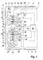
- Fig. 1 shows a side view in a schematic representation an embodiment of an inventive Shield tunneling machine for an earth pressure-based or liquid-supported degradation when used as intended Use in dismantling direction front area.
- the Schildvortriebsmaschine a shield tail 1, in the end region in the illustration according to FIG. 1 a number of segments 2 for lining a tunnel tube can be seen.
- a shield 3 and a cutter assembly 4 for the removal of material between an outer circumferential path and one between the outer circumferential track and a Central axis lying inner circumferential path exists, the has a circular outer periphery.
- the cutter assembly 4 from a flat outer cutter 5 and a concentric disposed within the outer cutter wheel 5 flat inner cutter 6 constructed.
- the inner cutter wheel 6 extends radially from the central axis to an intermediate diameter defining the inner circumferential path.
- the outer cutter 5 is composed of the intermediate diameter substantially to the through the shield 3 predetermined, defining the outer circumferential path Outside diameter of the shield tunneling machine continues.
- the outer cutter 5 is provided with a number of axially in the degradation direction equipped with the above outer removal tools 7, while the inner cutter 6 with a number of axially in the degradation direction above internal degradation tools 8 is busy.
- a working space 10 is present, the over the entire diameter of the shield tunneling machine extends.
- the working space 10 is radial from the shield 3, in the direction of degradation by the cutter assembly 4 and contrary to the degradation direction of a pressure-tight rear wall 11 limited.
- On the cutting wheels 5, 6 are a number of axially projecting into the working space 10 rotor mixing arms 12 attached, which is thus with the cutting wheels 5, 6 rotate.
- On the rear wall 11 are a number of axially in the Removal space 10 projecting stationary Stator mixer arms 13 attached. The rotor mixing arms 12 and the stator mixing arms 13 cause a further homogenization of the cutting wheels 5, 6 conveyed into the working space 10 and There already preconditioned material.
- the rear wall 11 is composed of an outer part 14 and a built inside part 15.
- the outer part 14 takes an outer Drive unit 16 of a drive, which via radially to externally angled outer connecting arms 17 with the outer cutter 5 is in communication and for rotating the outer cutting wheel 5 is set up.
- the inner part 15 of the Rear wall 11 takes an inner drive unit 18 of the drive on, via straight inner connecting arms 19 with the inner Cutting wheel 6 is in communication and for turning the inner cutter wheel 6 is set up.
- the outer drive unit 16 has a number of outer gears 20 and inner gears 21, which with a Control unit 22 are in communication.
- the inner drive unit 18 is equipped with a number of gears 23, the also be in communication with the control unit 22.
- the cutting wheels 5, 6 in the opposite direction Operation act on each other opposing torques so that each other is adjustable so that it is resistant to rolling Propulsion, that is a propulsion, in which the Schildvortriebsmaschine in a negligible amount their central axis turns, takes place.
- outer Driving press 24 On the outer part 14 of the rear wall 11 engage outer Driving press 24, which is located in a direction of degradation Supported behind the rear wall 11 support frame 25.
- the relative to the outer part 14 axially displaceable inner Part 15 of the rear wall 11 acts with internal jacking press 26th together, which are also supported on the support frame 25.
- the inner jacking presses 26 and the outer Jacking presses 24 are independent of each other for advancement of the inner cutter 6 and the optionally also with different outer cutter wheel 5 Feed rates can be actuated.
- the shield tunneling machine according to the Fig. 1 illustrated embodiment with a conveyor equipped with a number of separate conveyor units features in the work areas of the cutting wheels 5, 6 are arranged.
- As conveying units in the working area of the outer cutter 5 are a first screw conveyor 27 and a second screw conveyor 28 is provided, which in the bottom area the processing space 10 offset in the radial direction are arranged to each other to a mutual fluid mechanical To avoid shading.
- a third screw conveyor 29 is present, the slightly below the central axis of the shield tunneling machine is arranged.
- the throughput of the first and second screw conveyors 27, 28 and the third Screw conveyor 29 correspond approximately to the respective Surface portions of the outer cutter 5 and of the inner cutter 6.
- FIG. 2 shows the embodiment of FIG. 1 in one enlarged side view in the area of out of the outer Drive unit 16 and the inner drive unit 18 formed Drive.
- the outer gear 20 of the outer drive unit 16 are engaged with outer pinions 30, which in turn an outer toothed ring 31 engage, which with an outer Connecting flange 32 is rotatably connected.
- On the outside Connecting flange 32 are the outer connecting arms 17th attached.
- the inner gears 21 of the outer drive unit 16 cooperate with internal pinions 33, which in an inner To engage toothed ring 34, which also with the outer Connecting flange 32 is rotatably connected.
- the gears 23 of the inner drive unit 18 drive pinion 35 on, which is in engagement with a toothed ring 36, which in turn over an inner connecting flange 37 with the inner connecting arms 19 communicates.
- the gear 20, 21 of the outer drive unit 16 and the Transmissions 23 of the inner drive unit 18 are of the control unit 22 independently controllable, so that the Cutting wheels 5, 6 act upon, opposing each other Torques are adjustable so that a verrollungsschreiber propulsion takes place. Furthermore, the gears 20, 21, 23 of the drive units 16, 18 from the control unit 22 for rotating the cutting wheels 5, 6 with different Angular speeds can be controlled to the rotational speeds the cutting wheels 5, 6 not only for setting of torques, but also to control the Pressure conditions and the effect of the rotor mixing arms 12th and stator mixing arms 13 in the processing space 10 to influence.
- FIG. 2 it can be seen that in the displacement plane between the outer part 14 and the inner part 15 of the Rear wall 11 and in the region of the connecting flanges 32, 37 Seals 38 are present to the processing space 10 to the Seal back wall 11.
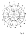
- FIG. 3 shows the embodiment of FIG. 1 in one Top view of the cutter assembly 4 against the direction of advance. From Fig. 3 it can be seen that the outer Cutting wheel 5 a number of outer cutting wheel openings 39th has, which lie between outer cutting arms 40. At the lateral edge of the outer cutter wheel openings 39 are the designed for relatively high rotational speeds outer mining tools 7 and the radially outer End reamer 41 arranged. The inner cutter 6 is with formed a number of inner cutter wheel openings 42, which are arranged between inner cutting arms 43. At the lateral edge of the inner cutter wheel openings 42 are for relatively low rotational speeds designed inner Removal tools 8 provided. In operation of the shield tunneling machine is degraded by the cutting wheels 5, 6 degraded material through the cutting wheel openings 39, 42 in the working space 10th conveyed.
Landscapes
- Engineering & Computer Science (AREA)
- Mining & Mineral Resources (AREA)
- Environmental & Geological Engineering (AREA)
- Life Sciences & Earth Sciences (AREA)
- General Life Sciences & Earth Sciences (AREA)
- Geochemistry & Mineralogy (AREA)
- Geology (AREA)
- Excavating Of Shafts Or Tunnels (AREA)
Priority Applications (1)
| Application Number | Priority Date | Filing Date | Title |
|---|---|---|---|
| EP03024349A EP1526249A1 (fr) | 2003-10-24 | 2003-10-24 | Machine de creusement à bouclier |
Applications Claiming Priority (1)
| Application Number | Priority Date | Filing Date | Title |
|---|---|---|---|
| EP03024349A EP1526249A1 (fr) | 2003-10-24 | 2003-10-24 | Machine de creusement à bouclier |
Publications (1)
| Publication Number | Publication Date |
|---|---|
| EP1526249A1 true EP1526249A1 (fr) | 2005-04-27 |
Family
ID=34384617
Family Applications (1)
| Application Number | Title | Priority Date | Filing Date |
|---|---|---|---|
| EP03024349A Withdrawn EP1526249A1 (fr) | 2003-10-24 | 2003-10-24 | Machine de creusement à bouclier |
Country Status (1)
| Country | Link |
|---|---|
| EP (1) | EP1526249A1 (fr) |
Cited By (4)
| Publication number | Priority date | Publication date | Assignee | Title |
|---|---|---|---|---|
| CN102628365A (zh) * | 2012-04-13 | 2012-08-08 | 张永忠 | 矩形顶管主机 |
| CN103256058A (zh) * | 2013-05-16 | 2013-08-21 | 岑益南 | 数控全自动全断面岩石盾构机 |
| CN105781563A (zh) * | 2016-03-22 | 2016-07-20 | 东北大学 | 一种泥水平衡盾构机辅助换刀装置及其使用方法 |
| CN116950666A (zh) * | 2023-06-19 | 2023-10-27 | 南宁轨道交通集团有限责任公司 | 提高开挖面稳定性的矩形顶管机 |
Citations (6)
| Publication number | Priority date | Publication date | Assignee | Title |
|---|---|---|---|---|
| US1888085A (en) * | 1930-08-21 | 1932-11-15 | A L Connelly Co | Mining machine |
| US3061289A (en) * | 1959-11-13 | 1962-10-30 | Goodman Mfg Co | Rotary head tunneling machine |
| DE1182176B (de) * | 1958-11-13 | 1964-11-26 | Alkirk Inc | Grosslochbohrmaschine |
| GB1084906A (en) * | 1963-09-13 | 1967-09-27 | Smith Ind Internat Inc | Boring or tunnelling apparatus |
| DE4113208C2 (de) | 1991-04-23 | 1995-04-06 | Herrenknecht Gmbh | Schildvortriebsmaschine |
| JP2003041890A (ja) * | 2001-08-02 | 2003-02-13 | Shoji Makino | 掘進機 |
-
2003
- 2003-10-24 EP EP03024349A patent/EP1526249A1/fr not_active Withdrawn
Patent Citations (6)
| Publication number | Priority date | Publication date | Assignee | Title |
|---|---|---|---|---|
| US1888085A (en) * | 1930-08-21 | 1932-11-15 | A L Connelly Co | Mining machine |
| DE1182176B (de) * | 1958-11-13 | 1964-11-26 | Alkirk Inc | Grosslochbohrmaschine |
| US3061289A (en) * | 1959-11-13 | 1962-10-30 | Goodman Mfg Co | Rotary head tunneling machine |
| GB1084906A (en) * | 1963-09-13 | 1967-09-27 | Smith Ind Internat Inc | Boring or tunnelling apparatus |
| DE4113208C2 (de) | 1991-04-23 | 1995-04-06 | Herrenknecht Gmbh | Schildvortriebsmaschine |
| JP2003041890A (ja) * | 2001-08-02 | 2003-02-13 | Shoji Makino | 掘進機 |
Non-Patent Citations (1)
| Title |
|---|
| PATENT ABSTRACTS OF JAPAN vol. 2003, no. 06 3 June 2003 (2003-06-03) * |
Cited By (6)
| Publication number | Priority date | Publication date | Assignee | Title |
|---|---|---|---|---|
| CN102628365A (zh) * | 2012-04-13 | 2012-08-08 | 张永忠 | 矩形顶管主机 |
| CN103256058A (zh) * | 2013-05-16 | 2013-08-21 | 岑益南 | 数控全自动全断面岩石盾构机 |
| CN103256058B (zh) * | 2013-05-16 | 2015-07-29 | 岑益南 | 数控全自动全断面岩石盾构机 |
| CN105781563A (zh) * | 2016-03-22 | 2016-07-20 | 东北大学 | 一种泥水平衡盾构机辅助换刀装置及其使用方法 |
| CN105781563B (zh) * | 2016-03-22 | 2017-12-01 | 东北大学 | 一种泥水平衡盾构机辅助换刀装置及其使用方法 |
| CN116950666A (zh) * | 2023-06-19 | 2023-10-27 | 南宁轨道交通集团有限责任公司 | 提高开挖面稳定性的矩形顶管机 |
Similar Documents
| Publication | Publication Date | Title |
|---|---|---|
| DE4113208C2 (de) | Schildvortriebsmaschine | |
| DE2534984C3 (de) | Schildvortriebsmaschine | |
| WO2008025555A1 (fr) | Procédé et dispositif pour l'usinage par fraisage de matériaux | |
| DE2162314C3 (de) | Erdbohrmaschine | |
| DE69001464T2 (de) | Schildvortriebsmaschine. | |
| DE10296375T5 (de) | Schild-Tunnelvortriebsverfahren und Schild-Tunnelvortriebsmaschine | |
| DE1459880B1 (de) | Vortriebsschild | |
| DE19652835C1 (de) | Schlitzwandfräse | |
| WO2023165796A1 (fr) | Dispositif de coupe de paroi de diaphragme et procédé de production d'une tranchée dans le sol | |
| DE3875247T2 (de) | Schildvortriebsmaschine. | |
| DE19906687A1 (de) | Doppelkopfbohrvorrichtung kurzer Bauart | |
| EP1395735B1 (fr) | Systeme de rotor pour fraisage de sol ou de mine | |
| DE19609899A1 (de) | Vorrichtung zur Herstellung eines Erdlochs | |
| DE3222923C2 (de) | Fördereinrichtung für eine Schildvortriebsmaschine | |
| DE3911378C2 (de) | Vortriebsschild mit einem Kegelbrecher, insbesondere zur Verwendung für den Rohrvorpreßbetrieb | |
| EP0146918B1 (fr) | Système de forage de tunnel pour l'avancement des tunnels par poussage de tubes | |
| EP1525370B1 (fr) | Dispositif pour realiser des forages dans la terre | |
| DE102014113602A1 (de) | Vorrichtung zur Förderung des Abbaubodens in einer Schildvortriebsmaschine (SVM) | |
| DE202020000396U1 (de) | Schildvortriebsmaschine für Tunnelbau | |
| DE2909395A1 (de) | Schuerfeinrichtung fuer den vortrieb von tunneln, stollen oder sonstigen hohlraeumen | |
| EP0155540B1 (fr) | Appareil fonctionnant comme excavateur, pour la pose souterraine de tubes par poussage | |
| DE4034220A1 (de) | Waelzlagerung fuer einen kegelbrecher | |
| DE2448753B1 (de) | Schneidkopf fuer vortriebs- und gewinnungsmaschinen im berg- und tunnelbau | |
| DE1583037C3 (de) | Ausleger für eine Vortriebsmaschine, insbesondere eine Tunnelbohrmaschine | |
| DE1459866A1 (de) | Tunnelbohrmaschine |
Legal Events
| Date | Code | Title | Description |
|---|---|---|---|
| PUAI | Public reference made under article 153(3) epc to a published international application that has entered the european phase |
Free format text: ORIGINAL CODE: 0009012 |
|
| AK | Designated contracting states |
Kind code of ref document: A1 Designated state(s): AT BE BG CH CY CZ DE DK EE ES FI FR GB GR HU IE IT LI LU MC NL PT RO SE SI SK TR |
|
| AX | Request for extension of the european patent |
Extension state: AL LT LV MK |
|
| AKX | Designation fees paid | ||
| STAA | Information on the status of an ep patent application or granted ep patent |
Free format text: STATUS: THE APPLICATION IS DEEMED TO BE WITHDRAWN |
|
| 18D | Application deemed to be withdrawn |
Effective date: 20051028 |
|
| REG | Reference to a national code |
Ref country code: DE Ref legal event code: 8566 |