EP1526192A1 - Electrolytic process for depositing a graded layer on a substrate and component - Google Patents
Electrolytic process for depositing a graded layer on a substrate and component Download PDFInfo
- Publication number
- EP1526192A1 EP1526192A1 EP03024373A EP03024373A EP1526192A1 EP 1526192 A1 EP1526192 A1 EP 1526192A1 EP 03024373 A EP03024373 A EP 03024373A EP 03024373 A EP03024373 A EP 03024373A EP 1526192 A1 EP1526192 A1 EP 1526192A1
- Authority
- EP
- European Patent Office
- Prior art keywords
- component
- substrate
- layer
- electrolyte
- current
- Prior art date
- Legal status (The legal status is an assumption and is not a legal conclusion. Google has not performed a legal analysis and makes no representation as to the accuracy of the status listed.)
- Withdrawn
Links
Images


Classifications
-
- C—CHEMISTRY; METALLURGY
- C25—ELECTROLYTIC OR ELECTROPHORETIC PROCESSES; APPARATUS THEREFOR
- C25D—PROCESSES FOR THE ELECTROLYTIC OR ELECTROPHORETIC PRODUCTION OF COATINGS; ELECTROFORMING; APPARATUS THEREFOR
- C25D5/00—Electroplating characterised by the process; Pretreatment or after-treatment of workpieces
- C25D5/10—Electroplating with more than one layer of the same or of different metals
-
- C—CHEMISTRY; METALLURGY
- C25—ELECTROLYTIC OR ELECTROPHORETIC PROCESSES; APPARATUS THEREFOR
- C25D—PROCESSES FOR THE ELECTROLYTIC OR ELECTROPHORETIC PRODUCTION OF COATINGS; ELECTROFORMING; APPARATUS THEREFOR
- C25D15/00—Electrolytic or electrophoretic production of coatings containing embedded materials, e.g. particles, whiskers, wires
- C25D15/02—Combined electrolytic and electrophoretic processes with charged materials
-
- C—CHEMISTRY; METALLURGY
- C25—ELECTROLYTIC OR ELECTROPHORETIC PROCESSES; APPARATUS THEREFOR
- C25D—PROCESSES FOR THE ELECTROLYTIC OR ELECTROPHORETIC PRODUCTION OF COATINGS; ELECTROFORMING; APPARATUS THEREFOR
- C25D21/00—Processes for servicing or operating cells for electrolytic coating
- C25D21/12—Process control or regulation
- C25D21/14—Controlled addition of electrolyte components
-
- C—CHEMISTRY; METALLURGY
- C25—ELECTROLYTIC OR ELECTROPHORETIC PROCESSES; APPARATUS THEREFOR
- C25D—PROCESSES FOR THE ELECTROLYTIC OR ELECTROPHORETIC PRODUCTION OF COATINGS; ELECTROFORMING; APPARATUS THEREFOR
- C25D5/00—Electroplating characterised by the process; Pretreatment or after-treatment of workpieces
- C25D5/18—Electroplating using modulated, pulsed or reversing current
-
- C—CHEMISTRY; METALLURGY
- C25—ELECTROLYTIC OR ELECTROPHORETIC PROCESSES; APPARATUS THEREFOR
- C25D—PROCESSES FOR THE ELECTROLYTIC OR ELECTROPHORETIC PRODUCTION OF COATINGS; ELECTROFORMING; APPARATUS THEREFOR
- C25D5/00—Electroplating characterised by the process; Pretreatment or after-treatment of workpieces
- C25D5/20—Electroplating using ultrasonics, vibrations
-
- F—MECHANICAL ENGINEERING; LIGHTING; HEATING; WEAPONS; BLASTING
- F01—MACHINES OR ENGINES IN GENERAL; ENGINE PLANTS IN GENERAL; STEAM ENGINES
- F01D—NON-POSITIVE DISPLACEMENT MACHINES OR ENGINES, e.g. STEAM TURBINES
- F01D5/00—Blades; Blade-carrying members; Heating, heat-insulating, cooling or antivibration means on the blades or the members
- F01D5/005—Repairing methods or devices
-
- F—MECHANICAL ENGINEERING; LIGHTING; HEATING; WEAPONS; BLASTING
- F01—MACHINES OR ENGINES IN GENERAL; ENGINE PLANTS IN GENERAL; STEAM ENGINES
- F01D—NON-POSITIVE DISPLACEMENT MACHINES OR ENGINES, e.g. STEAM TURBINES
- F01D5/00—Blades; Blade-carrying members; Heating, heat-insulating, cooling or antivibration means on the blades or the members
- F01D5/12—Blades
- F01D5/28—Selecting particular materials; Particular measures relating thereto; Measures against erosion or corrosion
- F01D5/288—Protective coatings for blades
-
- Y—GENERAL TAGGING OF NEW TECHNOLOGICAL DEVELOPMENTS; GENERAL TAGGING OF CROSS-SECTIONAL TECHNOLOGIES SPANNING OVER SEVERAL SECTIONS OF THE IPC; TECHNICAL SUBJECTS COVERED BY FORMER USPC CROSS-REFERENCE ART COLLECTIONS [XRACs] AND DIGESTS
- Y10—TECHNICAL SUBJECTS COVERED BY FORMER USPC
- Y10T—TECHNICAL SUBJECTS COVERED BY FORMER US CLASSIFICATION
- Y10T428/00—Stock material or miscellaneous articles
- Y10T428/31—Surface property or characteristic of web, sheet or block
Definitions
- the invention relates to an electrolytic method for deposition a graded layer on a substrate according to claim 1 and a component produced by this method according to claim 21.
- Various methods are known to apply layers to apply a substrate. These are e.g. Plasma spraying, galvanic deposition or vapor deposition, etc.
- DE 39 43 669 C2 discloses a method and a device for electrolytic surface treatment, in which a Mixing of the mass parts used for coating by vibration movement and / or rotational movement takes place, so deposited a uniform electrolytic layer becomes.
- US 2001/00 54 559 A1 discloses an electrolytic coating process, where pulsed currents are used, around the unwanted evolution of hydrogen during prevent electrolytic coatings of metals.
- DE 196 53 681 C2 discloses a method for electrolytic Deposition of a pure copper layer in which a Pulse current or pulse voltage method is used.
- the object is achieved by an electrolytic process for depositing a graded layer on a substrate according to Claim 1 and a component according to claim 21.
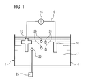
- FIG. 1 shows, by way of example, schematically a device 1 with which the method according to the invention is to be carried out.
- a container 4 Arranged in a container 4 are an electrolyte 7, an electrode 10 and a component as substrate 13 to be coated.
- the substrate 13 to be coated is, for example, a turbine component (turbine blade 120, 130 (FIG. 5), a combustion liner 155 (FIG. 6) or another housing part of a steam or gas turbine 100 (FIG. 5)) made of an iron, nickel or cobalt base superalloy and may already have a layer (MCrAlX) on its surface.
- the component 13 can either be newly manufactured or remanufactured. Refurbishment means that after use, components may be separated from layers (thermal barrier coating) and corrosion and oxidation products removed, for example by acid treatment (acid stripping). If necessary, cracks still have to be repaired. Thereafter, such a component can be coated again.
- acid treatment acid stripping
- the substrate 13 and the electrode 10 are via electrical Supply lines 19 with a current or voltage source 16 electrically connected.
- the current or voltage source 16 may be pulsed electrical currents or voltages (FIG. 2) produce.
- the individual components 28, 31 of an alloy are included, which are to be deposited on the substrate 13.
- the electrolyte 7 contains the first constituent 28 and the second constituent 31 of an alloy.
- the components 28, 31 are deposited on the substrate 13.
- the components 28, 31 may be metallic and / or ceramic. Also, all components may be metallic or ceramic only.
- gradients in the chemical composition can be produced in the layer to be produced by suitable choice of the process parameters.
- an alloy MCrAlX is deposited on the substrate 13, wherein M stands for at least one element of the group iron, cobalt or nickel.
- the introduction of the alloying elements Cr, Al, X and optionally further elements is carried out either by adding suitable soluble salts to the electrolyte or by suspending fine-grained, insoluble powders in the galvanic bath, which deposit as solid particles.
- suitable soluble salts to the electrolyte or by suspending fine-grained, insoluble powders in the galvanic bath, which deposit as solid particles.
- at least two components are dissolved, for example, in the form of salts in the electrolyte 7.
- the deposited Be homogenized or compacted layer or certain phases can be set in the layer.
- An ultrasonic probe 22 disposed in the electrolyte 7 can be and is controlled by an ultrasonic generator 25, improves the hydrodynamics and the mixing of the ingredients 28, 31 in the region of the substrate 13 and accelerated the deposition process.
- the current / voltage level For each component 28, 31 of the alloy, the current / voltage level, set the pulse duration and the pause become.
- FIG. 2 shows an example of a sequence of current pulses that repeat themselves.
- a sequence 34 consists of at least two blocks 37.
- Each block 37 consists of at least one, in particular two or more current pulses 40.
- a current pulse 40 is characterized by its duration t on , its height I max and its shape (rectangle, triangle, ). Equally important as process parameters are the pauses between the individual current pulses 40 (t off ) and the pauses between the blocks 37.
- the sequence 34 consists for example of a first block 37 with three current pulses 40, between which in turn one Pause takes place. This is followed by a second block 37, the has a greater current level and six current pulses 40th consists. After another pause, four current pulses 40 follow in the reverse direction, i. with changed polarity, um a correction of the alloy composition, the hydrogen desorption or to achieve an activation.
- sequence 34 is followed by a further block 37 four current pulses.
- the sequence 34 can be repeated several times be varied and also temporally.
- the individual pulse times t on are preferably of the order of magnitude of about 1 to 100 milliseconds.
- the duration of the block 37 is on the order of up to 10 seconds, so that up to 5000 pulses are emitted in a block 37.
- a block 37 is matched with its parameters to a component 28, 31 of the alloy in order to achieve the best deposition of this constituent 28, 31. These can be determined in individual experiments.
- An optimized block 37 leads to an optimized deposition of the component optimized for this block 37, ie the duration and the type of deposition is improved.
- the other ingredients are also still deposited. This optimization can be carried out for at least one further, for example all components 31 of the alloy. Thus, the optimized composition of the components 28, 31 is achieved.
- the proportion of the constituents 28, 31 in the layer to be applied can be determined. Gradients can also be generated in the layer. This is done by the parameters of the block 37, which is optimally matched to a component 28, 31, extended or shortened accordingly.
- non-alloy components such as e.g. Secondary phases in which electrolytes 7 are contained and deposited become.
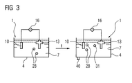
- FIG. 3 shows the time course of the method according to the invention.
- the device 1 comprises an electrolyte 7, the first component 28 is for example metallic and has the composition MCrAlX.
- constituents 28, 31 of the electrolyte 7 are particles, dissolved salts ,. if necessary plus wetting agents or additives understood that give the constituents 28, 31 in the layer to be produced.
- an MCrAlX layer is deposited electrolytically on the component 13.
- at least a second, further constituent 31 is fed into the container 4 and supplied to the electrolyte 7 and increases its concentration, so that the composition of the electrolyte 7 changes. This can be done in one step or the concentration of the ingredient 31 is increased continuously over time so that the concentration of the first ingredient 28 decreases in percentage.
- the composition of the electrolyte 7 is varied over time. Therefore, the component 13 need not be introduced into different containers 4 with different electrolytes 7.
- the second component 31 may also be present in the electrolyte 7 from the beginning and then further increased.
- the concentration of wetting agents and other additives can also be varied.
- the further constituent 31 is likewise deposited, with the result that a layer graded according to the increase in the concentration of the constituent 31 results.
- the graded layer is a composite material and is also referred to as a composite.
- a matrix is formed with the constituent 28 containing the secondary phase 31, the proportion of which may vary within the matrix.
- the proportion of constituent 31 can also be increased in this way that inversely the matrix through the component 31 and the secondary phase is formed by the component 28.
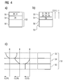
- FIG. 4 shows, by way of example, layer systems which are described by FIGS temporal variation of the composition of the electrolyte 7 can arise.
- FIG. 4 a shows a substrate 50 on which a layer 53 has been deposited electrolytically.
- a layer 54 is formed which has only the composition of constituent 28.
- the concentration of the further constituent 31 was increased in one step, so that the material composition of the layer 55 to be deposited changes.
- a further layer 55 which comprises the constituents of the electrolyte 7, consisting of the constituents 28, 31. It forms a layer system 53.
- FIG. 4c shows a further layer system 53, which has been produced by the method according to the invention.
- the layer system 53 has multi-graded layers 54, 55.
- the concentration of the material of the substrate 50 falls outwardly to the end of the layer 54 or earlier to a certain value, zero here.
- the concentration of the constituent 28 of the first layer 54 increases.
- the concentration of the component 28 in the second layer 55 decreases again.
- the value of the concentration of the component 28 may decrease to zero or a value other than zero.
- the concentration of the constituent 31 in the layer 55 increases accordingly.
- the substrate 50 consists for example of an iron-, nickel- or cobalt-based superalloy
- the layer 54 may be an MCrAlX layer on which a ceramic thermal barrier coating 55 (ZrO 2 ) is applied.
- the concentration of the ingredients 28, 31 can also be through Variation of the deposition parameters such as current density, voltage, Pulse and pause time are additionally influenced by these parameters of the current / voltage pulses specifically to the Abscheidungs the component 28, 31 are adjusted.
- FIG. 5 shows a gas turbine 100 in a partial longitudinal section.
- the gas turbine 100 has inside about a rotation axis 102 rotatably mounted rotor 103, which also serves as a turbine runner referred to as.
- rotor 103 Along the rotor 103 follow each other an intake housing 104, a compressor 105, an example Toroidal combustion chamber 110, in particular annular combustion chamber 106, with several coaxially arranged burners 107, a turbine 108 and the exhaust housing 109.
- the annular combustion chamber 106 communicates with an example annular Hot gas channel 111.
- Each turbine stage 112 is formed of two blade rings. As seen in the flow direction of a working medium 113 follows in the hot gas duct 111 of a guide vane 115 a from Blades 120 series 125 formed.
- the vanes 130 are attached to the stator 143, whereas the blades 120 of a series 125 by means of a Turbine disk 133 are mounted on the rotor 103.
- On the rotor 103 is coupled to a generator or a work machine (not shown).
- the gas turbine 100 During operation of the gas turbine 100 is from the compressor 105 sucked and compressed by the intake 104 104 air 135.
- the provided at the turbine end of the compressor 105 compressed air is fed to the burners 107 and mixed there with a fuel.
- the mixture is then to form the working medium 113 in the combustion chamber 110 burned. From there, the working medium flows 113 along the hot gas channel 111 past the vanes 130 and the blades 120. Relaxed on the blades 120 the working medium 113 is pulse-transmitting, so that the blades 120 drive the rotor 103 and this the attached to him work machine.
- the components exposed to the hot working medium 113 are subject to thermal loads during operation of the gas turbine 100.
- the guide vanes 130 and rotor blades 120 of the first turbine stage 112, viewed in the direction of flow of the working medium 113, are subjected to the greatest thermal stress in addition to the heat shield bricks lining the annular combustion chamber 106.
- they have a substrate, a directional structure, ie, they are monocrystalline (SX) or longitudinal (DS structure). In order to withstand the temperatures prevailing there, they are cooled by means of a coolant.
- the vane 130 has an inner housing 138 of the Turbine 108 facing Leitschaufelfuß (not shown here) and a vane foot opposite Guide vane head on.
- the vane head is the rotor 103 facing and on a mounting ring 140 of the stator 143rd established.
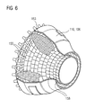
- FIG. 6 shows a combustion chamber of a gas turbine.
- the combustion chamber 110 is configured, for example, as a so-called annular combustion chamber, in which a plurality of burners 102 arranged around the turbine shaft 103 in the circumferential direction open into a common combustion chamber space.
- the combustion chamber 110 is configured in its entirety as an annular structure, which is positioned around the turbine shaft 103 around.
- the working medium M of about 1000 ° C to 1600 ° C designed.
- the combustion chamber wall 153 on its the working medium M facing side with one of heat shield elements 155 formed inner lining provided.
- Each heat shield element 155 is working medium side with a particularly heat-resistant Protective layer produced according to the invention can be equipped or made of high temperature resistant Material made. Due to the high temperatures inside the combustion chamber 110 is also for the heat shield elements 155 or provided for the holding elements, a cooling system.
- the combustion chamber 110 is in particular for a detection of Losses of the heat shield elements 155 designed. These are between the combustion chamber wall 153 and the heat shield elements 155, a number of temperature sensors 158 are positioned.
Abstract
Description
Die Erfindung betrifft ein elektrolytisches Verfahren zum Abscheiden einer gradierten Schicht auf ein Substrat gemäss Anspruch 1 und ein Bauteil hergestellt nach diesem Verfahren gemäss Anspruch 21.The invention relates to an electrolytic method for deposition a graded layer on a substrate according to claim 1 and a component produced by this method according to claim 21.
Es sind verschiedene Verfahren bekannt, um Schichten auf einem Substrat aufzubringen. Dies sind z.B. Plasmaspritzen, galvanische Abscheidung oder Aufdampfverfahren, u.a..Various methods are known to apply layers to apply a substrate. These are e.g. Plasma spraying, galvanic deposition or vapor deposition, etc.
Ein Artikel von G. Devaray im Bulletin of Electrochemistry 8 (8), 1992, pp. 390-392 mit dem Titel "Electro deposited composites- a review on new technologies for aerospace and other field" gibt eine Übersicht über Verfahren zur elektrochemischen Abscheidung von Schichten.An article by G. Devaray in the Bulletin of Electrochemistry 8 (8), 1992, pp. 390-392 entitled "Electro deposited composites" a review on new technologies for aerospace and other field "gives an overview of electrochemical processes Deposition of layers.
Die DE 101 13 767 A1 offenbart ein elektrolytisches Plattierungsverfahren.DE 101 13 767 A1 discloses an electrolytic plating method.
Die DE 39 43 669 C2 offenbart ein Verfahren und eine Vorrichtung zur elektrolytischen Oberflächenbehandlung, bei dem eine Durchmischung der verwendeten Massenteile zur Beschichtung durch Schwingungsbewegung und/oder Drehbewegung erfolgt, damit eine gleichmäßige elektrolytische Schicht abgeschieden wird.DE 39 43 669 C2 discloses a method and a device for electrolytic surface treatment, in which a Mixing of the mass parts used for coating by vibration movement and / or rotational movement takes place, so deposited a uniform electrolytic layer becomes.
Weitere elektrolytische Verfahren zur Beschichtung sind bekannt
aus der GB 2 167 446 A, der EP 443 877 A1 sowie aus dem
Artikel von J. Zahavi et al in Plating and Surface Finishing,
Jan. 1982, S. 76 ff. "Properties of electrodeposited composite
coatings" bei denen ungelöste Teilchen im Elektrolyten
verwendet werden, um diese in der Schicht mit abzuscheiden. Other electrolytic coating processes are known
from
In Electrochemical Society Proceedings Vol. 95-18, S. 543 ff. von Sarhadi et al. mit dem Titel "Development of a low current density electroplating bath ..." ist die Verwendung von Bädern beschrieben, die Kobalt-, Nickel- oder Eisenverbindungen enthalten.In Electrochemical Society Proceedings Vol. 95-18, p. 543 et seq. by Sarhadi et al. entitled "Development of a low current density electroplating bath ... "is the use of Baths described the cobalt, nickel or iron compounds contain.
Die US-PS 6,375,823 B1 beschreibt eine elektrolytische Beschichtungsmethode, bei der eine Ultraschallsonde verwendet wird.US Pat. No. 6,375,823 B1 describes an electrolytic coating method, when using an ultrasound probe becomes.
Die DE 195 45 231 A1 beschreibt ein Verfahren zur elektrolytischen Abscheidung von Metallschichten, bei dem ein Pulsstrom- oder Pulsspannungsverfahren verwendet wird. Dies wird jedoch nur angewendet, um Alterungserscheinungen von Abscheidebädern zu verringern.DE 195 45 231 A1 describes a method for electrolytic Deposition of metal layers, in which a pulse current or pulse voltage method is used. this will however only applied to aging phenomena of separation baths to reduce.
Die US 2001/00 54 559 A1 offenbart ein elektrolytisches Beschichtungsverfahren, bei dem gepulste Ströme verwendet werden, um die unerwünschte Entwicklung von Wasserstoff während elektrolytischer Beschichtungen von Metallen zu verhindern.US 2001/00 54 559 A1 discloses an electrolytic coating process, where pulsed currents are used, around the unwanted evolution of hydrogen during prevent electrolytic coatings of metals.
Die DE 196 53 681 C2 offenbart ein Verfahren zur elektrolytischen Abscheidung von einer reinen Kupferschicht, bei der ein Pulsstrom- oder Pulsspannungsverfahren verwendet wird.DE 196 53 681 C2 discloses a method for electrolytic Deposition of a pure copper layer in which a Pulse current or pulse voltage method is used.
Die DE 100 61 186 C1 beschreibt ein Verfahren zur galvanischen
Abscheidung, bei dem periodische Strompulse verwendet
werden.
V. Sova beschreibt in dem Artikel "Electrodeposited composite coatings for protection from high temperature corrosion" in Trans IMF 1987, 65, 21ff ein elektrolytisches Abscheidungsverfahren, bei dem im Elektrolyten ungelöste Partikel für die aufzubringende Schicht verwendet werden. Ebenso ist die Anwendung von Pulsströmen beschrieben. V. Sova describes in the article "Electrodeposited composite coatings for protection from high temperature corrosion "in Trans IMF 1987, 65, 21ff an electrolytic deposition process, in the electrolyte in the undissolved particles for the applied layer to be applied. Likewise, the application described by pulse currents.
Mit den bekannten Verfahren aufgebrachte Schichten weisen unter den Bedingungen mancher Einsatzzwecke eine schlechte Haftung gegenüber dem Substrat auf. Außerdem können nur Materialien einer konstanten Zusammensetzung abgeschieden werden.With the known methods applied layers under the conditions of some purposes a bad one Adhesion to the substrate. Besides, only materials can be used a constant composition are deposited.
Es ist daher Aufgabe der Erfindung, die oben genannten Probleme zu überwinden.It is therefore an object of the invention to solve the above problems to overcome.
Die Aufgabe wird gelöst durch ein elektrolytisches Verfahren zum Abscheiden einer gradierten Schicht auf ein Substrat gemäß Anspruch 1 und ein Bauteil gemäss Anspruch 21.The object is achieved by an electrolytic process for depositing a graded layer on a substrate according to Claim 1 and a component according to claim 21.
Durch die zeitliche Variation der Zusammensetzung des Elektrolyten zur Erzeugung von gradierten Schichten wird die Haftung von Schichten auf dem Substrat und ggf. untereinander verbessert, da abrupte Materialübergänge zu vermeiden sind.Due to the temporal variation of the composition of the electrolyte the production of graded layers becomes the liability of layers on the substrate and possibly with each other improved, since abrupt material transitions are to be avoided.
Weitere vorteilhafte Ausgestaltungen des Verfahrens und des
Bauteils sind in den Unteransprüchen aufgelistet.
Die Verfahrensschritte der Unteransprüche sowie die Maßnahmen
zur Verbesserung des Bauteils können in vorteilhafter Weise
miteinander kombiniert werden.Further advantageous embodiments of the method and of the component are listed in the subclaims.
The method steps of the subclaims and the measures for improving the component can be combined with each other in an advantageous manner.
Ausführungsbeispiele der Erfindung sind in den Figuren näher erläutert. Embodiments of the invention are closer in the figures explained.
Es zeigen:
- Figur 1
- eine Vorrichtung, mit der das erfindungsgemäße Verfahren durchzuführen ist,
Figur 2- eine Sequenz von Strom/Spannungspulsen, die für ein erfindungsgemäßes Verfahren verwendet werden kann,
Figur 3- den zeitlichen Verlauf des erfindungsgemäßen Verfahrens,
- Figur 4a,b,c
- verschiedene Beispiele für eine Gradientenschicht,
- Figur 5
- eine Gasturbine und
- Figur 6
- eine Brennkammer.
- FIG. 1
- a device with which the method according to the invention is to be carried out,
- FIG. 2
- a sequence of current / voltage pulses that can be used for a method according to the invention,
- FIG. 3
- the time course of the method according to the invention,
- FIG. 4a, b, c
- different examples of a gradient layer,
- FIG. 5
- a gas turbine and
- FIG. 6
- a combustion chamber.
Figur 1 zeigt beispielhaft, schematisch eine Vorrichtung 1,
mit der das erfindungsgemäße Verfahren durchzuführen ist.
In einem Behälter 4 sind angeordnet ein Elektrolyt 7, eine
Elektrode 10 und ein Bauteil als zu beschichtendes Substrat
13.
Das zu beschichtende Substrat 13 ist beispielsweise ein Turbinenbauteil
(Turbinenschaufel 120, 130 (Fig. 5), eine Brennkammerauskleidung
155 (Fig. 6) oder ein anderes Gehäuseteil
einer Dampf- oder Gasturbine 100 (Fig. 5)) aus einer Eisen-,
Nickel- oder Kobalt-Basis-Superlegierung und kann schon eine
Schicht (MCrAlX) auf seiner Oberfläche aufweisen.FIG. 1 shows, by way of example, schematically a device 1 with which the method according to the invention is to be carried out. Arranged in a
The
Das Bauteil 13 kann entweder neu hergestellt oder wiederaufgearbeitet
sein.
Wiederaufarbeitung (Refurbishment) bedeutet, dass Bauteile
nach ihrem Einsatz gegebenenfalls von Schichten (Wärmedämmschicht)
getrennt werden und Korrosions- und Oxidationsprodukte
entfernt werden, beispielsweise durch eine Säurebehandlung
(Säurestrippen). Gegebenenfalls müssen noch Risse repariert
werden. Danach kann ein solches Bauteil wieder beschichtet
werden. Die Wiederaufarbeitung ist wirtschaftlich
interessant, da das Substrat 13 sehr teuer ist. The
Refurbishment means that after use, components may be separated from layers (thermal barrier coating) and corrosion and oxidation products removed, for example by acid treatment (acid stripping). If necessary, cracks still have to be repaired. Thereafter, such a component can be coated again. The reprocessing is economically interesting because the
Das Substrat 13 und die Elektrode 10 sind über elektrische
Zuleitungen 19 mit einer Strom- oder Spannungsquelle 16
elektrisch leitend verbunden. Die Strom- oder Spannungsquelle
16 kann gepulste elektrische Ströme- oder Spannungen (Fig. 2)
erzeugen.The
In dem Elektrolyten 7 sind beispielsweise die einzelnen Bestandteile
28, 31 einer Legierung enthalten, die auf dem Substrat
13 abgeschieden werden sollen. So enthält der Elektrolyt
7 beispielsweise den ersten Bestandteil 28 und den zweiten
Bestandteil 31 einer Legierung.
Durch geeignete Wahl der Prozessparameter (Fig. 2) werden die
Bestandteile 28, 31 auf dem Substrat 13 abgeschieden. Die Bestandteile
28, 31 können metallisch und/oder keramisch sein.
Auch können alle Bestandteile nur metallisch oder nur keramisch
sein.In the
By suitable choice of the process parameters (FIG. 2), the
Ebenso können in der herzustellenden Schicht durch geeignete
Wahl der Prozessparameter Gradienten in der chemischen Zusammensetzung
erzeugt werden.
Beispielsweise wird auf das Substrat 13 eine Legierung MCrAlX
abgeschieden, wobei M für zumindest ein Element der Gruppe
Eisen, Kobalt oder Nickel steht. Die Einbringung der Legierungselemente
Cr, Al, X und optional weitere Elemente erfolgt
entweder durch Zugabe geeigneter löslicher Salze zum Elektrolyten
oder durch Suspendierung von feinkörnigen, unlöslichen
Pulvern in das galvanische Bad, die sich als feste Partikel
abscheiden. Beispielsweise mindestens zwei Bestandteile sind
beispielsweise in Form von Salzen im Elektrolyt 7 gelöst.Likewise, gradients in the chemical composition can be produced in the layer to be produced by suitable choice of the process parameters.
For example, an alloy MCrAlX is deposited on the
Durch einen nachfolgenden thermischen Prozess kann die abgeschiedene Schicht homogenisiert oder verdichtet werden oder bestimmte Phasen können in der Schicht eingestellt werden.By a subsequent thermal process, the deposited Be homogenized or compacted layer or certain phases can be set in the layer.
Eine Ultraschallsonde 22, die im Elektrolyten 7 angeordnet
sein kann und durch einen Ultraschallgeber 25 gesteuert wird,
verbessert die Hydrodynamik und die Durchmischung der Bestandteile
28, 31 im Bereich des Substrats 13 und beschleunigt
den Abscheidungsprozess.An
Für jeden Bestandteil 28, 31 der Legierung kann die Strom/Spannungshöhe,
die Pulsdauer und die Pulspause festgelegt
werden.For each
Figur 2 zeigt eine beispielhafte Aneinanderreihung von Strompulsen,
die sich wiederholen.
Eine Sequenz 34 besteht aus zumindest zwei Blöcken 37.
Jeder Block 37 besteht aus zumindest einem, insbesondere zwei
oder mehreren Strompulsen 40.
Ein Strompuls 40 ist charakterisiert durch seine Dauer ton,
seine Höhe Imax und seine Form (Rechteck, Dreieck, ...).
Ebenso wichtig als Prozessparameter sind die Pausen zwischen
den einzelnen Strompulsen 40 (toff) und die Pausen zwischen
den Blöcken 37.FIG. 2 shows an example of a sequence of current pulses that repeat themselves.
A
Each
A
Die Sequenz 34 besteht beispielsweise aus einem ersten Block
37 mit drei Strompulsen 40, zwischen denen wiederum eine
Pause stattfindet. Darauf folgt ein zweiter Block 37, der
eine größere Stromhöhe aufweist und aus sechs Strompulsen 40
besteht. Nach einer weiteren Pause folgen vier Strompulse 40
in umgekehrter Richtung, d.h. mit geänderter Polarität, um
eine Korrektur der Legierungszusammensetzung, der Wasserstoff-Desorption
oder eine Aktivierung zu erreichen.The
Als Abschluss der Sequenz 34 folgt ein weiterer Block 37 mit
vier Strompulsen. Die Sequenz 34 kann mehrfach wiederholt
werden und auch zeitlich variiert werden.The conclusion of the
Die Einzelpulszeiten ton betragen vorzugsweise größenordnungsmäßig
etwa 1 bis 100 Millisekunden. Die zeitliche Dauer
des Blocks 37 liegt in der Größenordnung bis zu 10 Sekunden,
so dass bis zu 5000 Pulse in einem Block 37 ausgesendet werden. The individual pulse times t on are preferably of the order of magnitude of about 1 to 100 milliseconds. The duration of the
Die Belegung sowohl während der Pulsabfolgen als auch in der Pausenzeit mit einem geringen Potential (Basisstrom) ist optional möglich. Somit wird eine Unterbrechung der Elektroabscheidung, die Inhomogenitäten verursachen kann, vermieden.The occupancy both during the pulse sequences as well as in the Pause time with a low potential (base current) is optional possible. Thus, an interruption of the electrodeposition, which can cause inhomogeneities avoided.
Ein Block 37 ist mit seinen Parametern auf ein Bestandteil
28, 31 der Legierung abgestimmt, um die beste Abscheidung
dieses Bestandteils 28, 31 zu erreichen. Diese können in Einzelversuchen
bestimmt werden. Ein optimierter Block 37 führt
zu einer optimierten Abscheidung des auf diesen Block 37 optimierten
Bestandteils, d.h. die Zeitdauer und die Art der
Abscheidung wird verbessert. Die anderen Bestandteile werden
aber ebenfalls noch abgeschieden.
Diese Optimierung kann für zumindest einen weiteren, beispielsweise
alle Bestandteile 31 der Legierung durchgeführt
werden.
Somit wird die optimierte Zusammensetzung der Bestandteile
28, 31 erreicht.A
This optimization can be carried out for at least one further, for example all
Thus, the optimized composition of the
Beispielsweise durch die Dauer der einzelnen Blöcke 37 kann
der Anteil der Bestandteile 28, 31 in der aufzubringenden
Schicht festgelegt werden.
Gradienten können ebenso in der Schicht erzeugt werden. Dies
geschieht dadurch, dass die Parameter des Blocks 37, der auf
einen Bestandteil 28, 31 optimal abgestimmt ist, entsprechend
verlängert oder verkürzt wird.For example, by the duration of the individual blocks 37, the proportion of the
Gradients can also be generated in the layer. This is done by the parameters of the
Ebenso können weitere Nichtlegierungsbestandteile, wie z.B.
Sekundärphasen, in dem Elektrolyten 7 enthalten sein und abgeschieden
werden.Likewise, other non-alloy components, such as e.g.
Secondary phases in which
Figur 3 zeigt den zeitlichen Verlauf des erfindungsgemäßen
Verfahrens.
Die Vorrichtung 1 weist einen Elektrolyten 7 auf, dessen erster
Bestandteil 28 beispielsweise metallisch ist und die Zusammensetzung
MCrAlX aufweist. FIG. 3 shows the time course of the method according to the invention.
The device 1 comprises an
Unter Bestandteilen 28, 31 des Elektrolyten 7 werden Partikel,
gelöste Salze,. ggf. plus Netzmittel oder Additive verstanden,
die in der herzustellenden Schicht die Bestandteile
28, 31 ergeben.
In bekannter Art und Weise wird eine MCrAlX-Schicht elektrolytisch
auf dem Bauteil 13 abgeschieden.
Im zeitlichen Verlauf wird zumindest ein zweiter, weiterer
Bestandteil 31 in den Behälter 4 zugeführt und dem Elektrolyten
7 zugeführt und dessen Konzentration erhöht, so dass sich
die Zusammensetzung des Elektrolyten 7 ändert. Dies kann in
einem Schritt erfolgen oder die Konzentration des Bestandteils
31 wird kontinuierlich mit der Zeit erhöht, so dass die
Konzentration des ersten Bestandteils 28 prozentual abnimmt.
Somit wird die Zusammensetzung des Elektrolyten 7 zeitlich
variiert. Daher muss das Bauteil 13 nicht in verschiedene Behälter
4 mit verschiedenen Elektrolyten 7 eingebracht werden.
Der zweite Bestandteil 31 kann auch von Anfang an im Elektrolyten
7 vorhanden sein und dann weiter erhöht werden.
Auch die Konzentration von Netzmitteln und weiteren Additiven
kann variiert werden.Among
In a known manner, an MCrAlX layer is deposited electrolytically on the
Over time, at least a second,
The concentration of wetting agents and other additives can also be varied.
Auch kann die Zusammensetzung des Elektrolyten 7 zusätzlich
zur Zugabe des Bestandteils 31, ggf. auch variiert werden
über ein Auslassventil 40, durch das Elektrolyt 7 mit dem Bestandteil
28 ausgelassen wird, so dass sich auch dadurch die
Konzentration des weiteren Bestandteils 31 in dem Elektrolyten
7 erhöht.
Der weitere Bestandteil 31 wird ebenfalls mit abgeschieden,
so dass sich eine je nach Erhöhung der Konzentration des Bestandteils
31 gradierte Schicht ergibt. Die gradierte Schicht
ist ein Verbundwerkstoff und wird auch als Komposit bezeichnet.
Am Anfang des Verfahrens bildet sich eine Matrix mit dem Bestandteil
28, die die Sekundärphase 31 enthält, deren Anteil
innerhalb der Matrix variieren kann. Also, the composition of the
The
At the beginning of the process, a matrix is formed with the constituent 28 containing the
Der Anteil des Bestandteils 31 kann auch so erhöht werden,
dass in umgekehrter Weise die Matrix durch den Bestandteil 31
und die Sekundärphase durch den Bestandteil 28 gebildet wird.The proportion of constituent 31 can also be increased in this way
that inversely the matrix through the
Figur 4 zeigt beispielhaft Schichtsysteme, die durch die
zeitliche Variation der Zusammensetzung des Elektrolyten 7
entstehen können.FIG. 4 shows, by way of example, layer systems which are described by FIGS
temporal variation of the composition of the
Figur 4a zeigt ein Substrat 50, auf dem eine Schicht 53
elektrolytisch abgeschieden worden ist.FIG. 4 a shows a
In einem ersten Verfahrensschritt wurden nur die Bestandteile
28 abgeschieden, wie es in Figur 3 für den ersten Verfahrensschritt
erläutert wurde. Es bildet sich eine Schicht 54, die
nur die Zusammensetzung des Bestandteils 28 aufweist.
In einem weiteren Verfahrensschritt wurde in einem Schritt
die Konzentration des weiteren Bestandteils 31 erhöht, so
dass sich die Materialzusammensetzung der abzuscheidenden
Schicht 55 verändert.
Somit bildet sich auf der Schicht 54 eine weitere Schicht 55,
die die Bestandteile des Elektrolyten 7, bestehend aus den
Bestandteilen 28, 31, aufweist.
Es bildet sich ein Schichtsystem 53.In a first method step, only the
In a further method step, the concentration of the
Thus, on the
It forms a
Gradierte Schichten können auch hergestellt werden, indem die
Zugabe des Bestandteils 31 in dem Elektrolyten 7 kontinuierlich
mit der Zeit t erhöht wird bzw. der Elektrolyt 7 mit dem
Bestandteil 28 abgeführt wird. Somit ergibt sich beispielsweise
eine Schicht wie in Figur 4b dargestellt.
Auf dem Substrat 50 ist wiederum zuerst nur eine Schicht gebildet
worden, die sich aus dem Bestandteil 28 des Elektrolyten
ergibt.
Durch stetige oder unstetige zeitliche Zunahme des Bestandteils
31 im Elektrolyten 7 steigt die Konzentration (c31)
dieses Bestandteils 31 in der Schicht 55 nach außen an. Graduated layers can also be produced by continuously increasing the addition of the constituent 31 in the
On the
By continuous or discontinuous increase in time of the constituent 31 in the
Es kann aber auch von Anfang an der Bestandteil 31 dem Elektrolyten
7 hinzugefügt werden, so dass sich ein Konzentrationsgradient
direkt ausgehend von dem Substrat 50 bildet.But it can also be from the beginning of the
Figur 4c zeigt ein weiteres Schichtsystem 53, das mit dem erfindungsgemäßen
Verfahren hergestellt worden ist.
Das Schichtsystem 53 weist mehrfach gradierte Schichten 54,
55 auf.
So fällt in einer ersten Schicht 54 auf dem Substrat 50 die
Konzentration des Materials des Substrats 50 nach außen hin
bis zum Ende der Schicht 54 oder früher auf einen bestimmten
Wert, hier null, ab.
Gleichzeitig erhöht sich die Konzentration des Bestandteils
28 der ersten Schicht 54.
Nachdem die Konzentration des Bestandteils 28 beispielsweise
zu 100% erreicht ist, sinkt die Konzentration des Bestandteils
28 in der zweiten Schicht 55 wieder ab.
Der Wert der Konzentration des Bestandteils 28 kann auf Null
oder einen von Null verschiedenen Wert abfallen. Gleichzeitig
erhöht sich entsprechend die Konzentration des Bestandteils
31 in der Schicht 55.FIG. 4c shows a
The
Thus, in a
At the same time, the concentration of the constituent 28 of the
For example, after the concentration of the
The value of the concentration of the
Das Substrat 50 besteht beispielsweise aus einer eisen-,
nickel- oder kobaltbasierten Superlegierung, die Schicht 54
kann eine MCrAlX-Schicht sein, auf der eine keramische Wärmedämmschicht
55 (ZrO2) aufgebracht ist.The
Die Konzentration der Bestandteile 28, 31 kann auch durch
Variation der Abscheidungsparameter wie Stromdichte, Spannung,
Puls- und Pausenzeit zusätzlich beeinflusst werden, indem
diese Parameter der Strom/Spannungspulse speziell an das
Abscheidungsverhalten der Bestandteils 28, 31 angepasst werden.The concentration of the
Die Figur 5 zeigt eine Gasturbine 100 in einem Längsteilschnitt. FIG. 5 shows a
Die Gasturbine 100 weist im Inneren einen um eine Rotationsachse
102 drehgelagerten Rotor 103 auf, der auch als Turbinenläufer
bezeichnet wird. Entlang des Rotors 103 folgen aufeinander
ein Ansauggehäuse 104, ein Verdichter 105, eine beispielsweise
torusartige Brennkammer 110, insbesondere Ringbrennkammer
106, mit mehreren koaxial angeordneten Brennern
107, eine Turbine 108 und das Abgasgehäuse 109. Die Ringbrennkammer
106 kommuniziert mit einem beispielsweise ringförmigen
Heißgaskanal 111. Dort bilden beispielsweise vier
hintereinandergeschaltete Turbinenstufen 112 die Turbine 108.
Jede Turbinenstufe 112 ist aus zwei Schaufelringen gebildet.
In Strömungsrichtung eines Arbeitsmediums 113 gesehen folgt
im Heißgaskanal 111 einer Leitschaufelreihe 115 eine aus
Laufschaufeln 120 gebildete Reihe 125.The
Die Leitschaufeln 130 sind dabei am Stator 143 befestigt, wohingegen
die Laufschaufeln 120 einer Reihe 125 mittels einer
Turbinenscheibe 133 am Rotor 103 angebracht sind. An dem Rotor
103 angekoppelt ist ein Generator oder eine Arbeitsmaschine
(nicht dargestellt).The
Während des Betriebes der Gasturbine 100 wird vom Verdichter
105 durch das Ansauggehäuse 104 Luft 135 angesaugt und verdichtet.
Die am turbinenseitigen Ende des Verdichters 105 bereitgestellte
verdichtete Luft wird zu den Brennern 107 geführt
und dort mit einem Brennmittel vermischt. Das Gemisch
wird dann unter Bildung des Arbeitsmediums 113 in der Brennkammer
110 verbrannt. Von dort aus strömt das Arbeitsmedium
113 entlang des Heißgaskanals 111 vorbei an den Leitschaufeln
130 und den Laufschaufeln 120. An den Laufschaufeln 120 entspannt
sich das Arbeitsmedium 113 impulsübertragend, so dass
die Laufschaufeln 120 den Rotor 103 antreiben und dieser die
an ihn angekoppelte Arbeitsmaschine.During operation of the
Die dem heißen Arbeitsmedium 113 ausgesetzten Bauteile unterliegen
während des Betriebes der Gasturbine 100 thermischen
Belastungen. Die Leitschaufeln 130 und Laufschaufeln 120 der
in Strömungsrichtung des Arbeitsmediums 113 gesehen ersten
Turbinenstufe 112 werden neben den die Ringbrennkammer 106
auskleidenden Hitzeschildsteinen am meisten thermisch belastet.
Sie weisen insbesondere ein Substrat, eine gerichtete
Struktur auf, d.h. sei sind einkristallin (SX) oder längsgerichtet
(DS-Struktur). Um den dort herrschenden Temperaturen
standzuhalten, werden diese mittels eines Kühlmittels gekühlt.
Ebenso können die Schaufeln 120, 130 Beschichtungen gegen
Korrosion (MCrAlX; M = Fe, Co, Ni, X=Y, Seltenen Erden) und
Wärme (Wärmedämmschicht, beispielsweise aus ZrO2 oder Y2O4-ZrO2
in Form stängelförmiger Körner (EP-PVD)) aufweisen, die
gradiert sind und mit oben beschriebenem Verfahren hergestellt
werden.The components exposed to the hot working
Likewise, the
Die Leitschaufel 130 weist einen dem Innengehäuse 138 der
Turbine 108 zugewandten Leitschaufelfuß (hier nicht dargestellt)
und einen dem Leitschaufelfuß gegenüberliegenden
Leitschaufelkopf auf. Der Leitschaufelkopf ist dem Rotor 103
zugewandt und an einem Befestigungsring 140 des Stators 143
festgelegt.The
Die Figur 6 zeigt eine Brennkammer einer Gasturbine.
Die Brennkammer 110 ist beispielsweise als so genannte Ringbrennkammer
ausgestaltet, bei der eine Vielzahl von in Umfangsrichtung
um die Turbinenwelle 103 herum angeordneten
Brennern 102 in einen gemeinsamen Brennkammerraum münden.
Dazu ist die Brennkammer 110 in ihrer Gesamtheit als ringförmige
Struktur ausgestaltet, die um die Turbinenwelle 103
herum positioniert ist.FIG. 6 shows a combustion chamber of a gas turbine.
The
Zur Erzielung eines vergleichsweise hohen Wirkungsgrades ist
die Brennkammer 110 für eine vergleichsweise hohe Temperatur
des Arbeitsmediums M von etwa 1000°C bis 1600°C ausgelegt. Um
auch bei diesen, für die Materialien ungünstigen Betriebsparametern
eine vergleichsweise lange Betriebsdauer zu ermöglichen,
ist die Brennkammerwand 153 auf ihrer dem Arbeitsmedium
M zugewandten Seite mit einer aus Hitzeschildelementen
155 gebildeten Innenauskleidung versehen. Jedes Hitzeschildelement
155 ist arbeitsmediumsseitig mit einer besonders hitzebeständigen
Schutzschicht, die erfindungsgemäß hergestellt
sein kann, ausgestattet oder aus hochtemperaturbeständigem
Material gefertigt. Aufgrund der hohen Temperaturen im Inneren
der Brennkammer 110 ist zudem für die Hitzeschildelemente
155 bzw. für deren Halteelemente ein Kühlsystem vorgesehen.To achieve a comparatively high efficiency
the
Die Brennkammer 110 ist insbesondere für eine Detektion von
Verlusten der Hitzeschildelemente 155 ausgelegt. Dazu sind
zwischen der Brennkammerwand 153 und den Hitzeschildelementen
155 eine Anzahl von Temperatursensoren 158 positioniert.The
Claims (23)
in einem elektrolytischen Verfahren,
wobei das Substrat (13, 50) für eine bestimmte Zeitdauer in einem Elektrolyten (7),
um eine Schicht (54, 55) aufzubringen, eingebracht wird,
dadurch gekennzeichnet, dass
die quantitative Zusammensetzung der Bestandteile (28, 31) des Elektrolyten (7) zeitlich variiert wird,
um die Gradierung der zumindest einen Schicht (54, 55) zu erreichen.Method for depositing a composite material comprising at least two components (28, 31) as at least one graded layer (53, 54, 55) on a substrate (13, 50),
in an electrolytic process,
wherein the substrate (13, 50) for a certain period of time in an electrolyte (7),
to apply a layer (54, 55) is introduced,
characterized in that
the quantitative composition of the constituents (28, 31) of the electrolyte (7) is varied over time,
to achieve grading of the at least one layer (54, 55).
dadurch gekennzeichnet, dass
das Substrat (13, 50) in einem mit dem Elektrolyten (7) gefüllten Behälter (4) angeordnet ist,
und dass die zeitliche Variation der Zusammensetzung des Elektrolyten (7) durch Zufuhr des zumindest zweiten Bestandteils (31) in den Behälter (4) erfolgt. Method according to claim 1,
characterized in that
the substrate (13, 50) is arranged in a container (4) filled with the electrolyte (7),
and that the time variation of the composition of the electrolyte (7) by supplying the at least second component (31) into the container (4).
dadurch gekennzeichnet, dass das Substrat (13, 50) in einem Behälter (4) angeordnet ist,
dass die zeitliche Variation der Zusammensetzung des Elektrolyten (7) dadurch erfolgt,
dass der Elektrolyt (7) mit dem zumindest ersten Bestandteil (28) zumindest teilweise aus einem Behälter (4) des Elektrolyten (7) entfernt wird, und
dass der zumindest zweite Bestandteil (31) zugeführt wird.Method according to claim 1 or 2,
characterized in that the substrate (13, 50) is arranged in a container (4),
that the temporal variation of the composition of the electrolyte (7) takes place thereby,
that the electrolyte (7) with the at least first component (28) is at least partially removed from a container (4) of the electrolyte (7), and
that the at least second component (31) is supplied.
dadurch gekennzeichnet, dass
der erste Bestandteil (28) metallisch, insbesondere eine Legierung ist.Method according to claim 1 or 3,
characterized in that
the first component (28) is metallic, in particular an alloy.
dadurch gekennzeichnet, dass
der erste Bestandteil (28) keramisch ist.Method according to claim 1 or 3,
characterized in that
the first component (28) is ceramic.
dadurch gekennzeichnet, dass
der zumindest zweite Bestandteil (31) keramisch ist.Method according to claim 1 or 2,
characterized in that
the at least second component (31) is ceramic.
dadurch gekennzeichnet, dass
der zumindest zweite Bestandteil (31) metallisch ist. Method according to claim 1 or 2,
characterized in that
the at least second component (31) is metallic.
dadurch gekennzeichnet, dass
zum elektrolytischen Abscheiden zumindest ein Strom/Spannungspuls (40) verwendet wird,
um ein optimiertes Abscheiden der einzelnen Legierungsbestandteile (28, 31) und/oder
um die Gradierung der Schicht (53, 54, 55) zu fördern.Method according to claim 1 or 4,
characterized in that
for electrolytic deposition at least one current / voltage pulse (40) is used,
to optimize the deposition of the individual alloy components (28, 31) and / or
to promote the gradation of the layer (53, 54, 55).
dadurch gekennzeichnet, dass
der Elektrolyt (7) in mechanische Schwingungen versetzt wird,
insbesondere durch eine Ultraschallsonde (22).Method according to claim 1 or 8,
characterized in that
the electrolyte (7) is set in mechanical vibration,
in particular by an ultrasound probe (22).
dadurch gekennzeichnet, dass
zum elektrolytischen Abscheiden ein Strom/Spannungspuls (40) verwendet wird, der in seinem zeitlichen Verlauf insbesondere durch eine Rechteck- oder Dreiecksform bestimmt ist.Method according to claim 8,
characterized in that
for electrolytic deposition a current / voltage pulse (40) is used, which is determined in its time course in particular by a rectangular or triangular shape.
dadurch gekennzeichnet, dass
zum elektrolytischen Abscheiden wobei sowohl positive als auch negative Strom/Spannungspulse (40) verwendet werden. Method according to claim 8 or 10,
characterized in that
for electrolytic deposition using both positive and negative current / voltage pulses (40).
dadurch gekennzeichnet, dass
für das elektrolytische Abscheiden mehrere Strom/Spannungspulse (40) verwendet werden,
die jeweils in einer Sequenz (34) zusammengefasst sind,
wobei die Sequenz (34) aus zumindest zwei verschiedenen Blöcken (37) besteht,
wobei ein Block (37) aus zumindest einem, insbesondere zumindest zwei Strompulsen (40) besteht.A method according to claim 8, 10 or 11
characterized in that
several current / voltage pulses (40) are used for the electrolytic deposition,
each summarized in a sequence (34),
wherein the sequence (34) consists of at least two different blocks (37),
wherein a block (37) consists of at least one, in particular at least two current pulses (40).
dadurch gekennzeichnet, dass
ein Block (37) bestimmt ist durch eine Anzahl von Strompulsen (40), Pulsdauer (ton), Pulspause (toff), Stromhöhe (Imax) und zeitlichem Verlauf.Method according to claim 12,
characterized in that
a block (37) is determined by a number of current pulses (40), pulse duration (t on ), pulse pause (t off ), current level (I max ) and time course.
dadurch gekennzeichnet, dass
ein Block (37) jeweils auf einen Bestandteil (28, 31) der Legierung abgestimmt ist,
um die beste Abscheidung des Bestandteils (28, 31) zu erreichen.Method according to claim 12 or 13,
characterized in that
a block (37) is in each case matched to a component (28, 31) of the alloy,
to achieve the best deposition of constituent (28, 31).
dadurch gekennzeichnet, dass
jeder Block (37) auf jeweils einen Bestandteil (28, 31) der Legierung abgestimmt ist,
um die beste Zusammensetzung der Bestandteile (28, 31) zu erreichen. Method according to claim 12 or 13,
characterized in that
each block (37) is tuned to a respective component (28, 31) of the alloy,
to achieve the best composition of ingredients (28, 31).
dadurch gekennzeichnet, dass
als Schicht eine MCrAlX-Legierung auf dem Substrat (13, 50) abgeschieden wird,
wobei M zumindest ein Element der Gruppe Eisen, Kobalt oder Nickel ist,
und X Yttrium und/oder zumindest ein Element der Seltenen Erden ist.Method according to claim 4 or 8,
characterized in that
as a layer, an MCrAlX alloy is deposited on the substrate (13, 50),
where M is at least one element of the group iron, cobalt or nickel,
and X is yttrium and / or at least one element of the rare earths.
dadurch gekennzeichnet, dass
in einer herzustellenden Legierungsschicht Gradienten in der Materialzusammensetzung durch zeitliche Variation des Strom/Spannungspulses (40) oder der Sequenz (34) beeinflusst werden.Method according to claim 8, 12, 13 or 16,
characterized in that
In an alloy layer to be produced, gradients in the material composition are influenced by temporal variation of the current / voltage pulse (40) or the sequence (34).
dadurch gekennzeichnet, dass
ein Basisstrom den Strompulsen (40) und/oder den Pausen überlagert ist.Method according to claim 8, 10 or 11,
characterized in that
a base current is superimposed on the current pulses (40) and / or the pauses.
dadurch gekennzeichnet, dass
als Substrat (13, 50) eine Turbinenschaufel (120, 130), eine Brennkammerauskleidung (155) oder andere Gehäuseteile einer Dampf- oder Gasturbine (100) beschichtet werden. Method according to claim 1,
characterized in that
a turbine blade (120, 130), a combustion chamber lining (155) or other housing parts of a steam or gas turbine (100) are coated as the substrate (13, 50).
dadurch gekennzeichnet, dass
als Substrat (13, 50) ein neuhergestelltes Bauteil oder ein wiederaufgearbeitetes Bauteil beschichtet wird.Method according to claim 19,
characterized in that
as the substrate (13, 50) a newly manufactured component or a remanufactured component is coated.
das ein Substrat (13, 50)
und zumindest eine Schicht (53, 54, 55) aufweist,
welche gradiert ist und nach einem oder mehreren der vorherigen Ansprüche hergestellt ist.component
a substrate (13, 50)
and at least one layer (53, 54, 55),
which is graded and manufactured according to one or more of the preceding claims.
dadurch gekennzeichnet, dass
auf dem Substrat (50) eine erste gradierte Schicht (54) aus einem ersten Material (28) aufgebracht ist, und
dass auf der ersten gradierten Schicht (54) eine zweite gradierte Schicht (55) aufgebracht ist,
wobei die Konzentration des ersten Materials (28) ausgehend vom Substrat (50) in der Schicht (55) abnimmt.Component according to claim 21,
characterized in that
on the substrate (50) a first graded layer (54) of a first material (28) is applied, and
a second graded layer (55) is applied to the first graded layer (54),
wherein the concentration of the first material (28) decreases from the substrate (50) in the layer (55).
dadurch gekennzeichnet, dass
ausgehend vom Substrat (50) die Konzentration des Substrats (50) in der ersten Schicht (54) abnimmt und die Konzentration des ersten Materials (28) in der Schicht (54) zunimmt.Component according to claim 21 or 22,
characterized in that
starting from the substrate (50), the concentration of the substrate (50) in the first layer (54) decreases and the concentration of the first material (28) in the layer (54) increases.
Priority Applications (2)
| Application Number | Priority Date | Filing Date | Title |
|---|---|---|---|
| EP03024373A EP1526192A1 (en) | 2003-10-24 | 2003-10-24 | Electrolytic process for depositing a graded layer on a substrate and component |
| US10/972,310 US20050109626A1 (en) | 2003-10-24 | 2004-10-22 | Electrolytic process for depositing a graduated layer on a substrate, and component |
Applications Claiming Priority (1)
| Application Number | Priority Date | Filing Date | Title |
|---|---|---|---|
| EP03024373A EP1526192A1 (en) | 2003-10-24 | 2003-10-24 | Electrolytic process for depositing a graded layer on a substrate and component |
Publications (1)
| Publication Number | Publication Date |
|---|---|
| EP1526192A1 true EP1526192A1 (en) | 2005-04-27 |
Family
ID=34384623
Family Applications (1)
| Application Number | Title | Priority Date | Filing Date |
|---|---|---|---|
| EP03024373A Withdrawn EP1526192A1 (en) | 2003-10-24 | 2003-10-24 | Electrolytic process for depositing a graded layer on a substrate and component |
Country Status (2)
| Country | Link |
|---|---|
| US (1) | US20050109626A1 (en) |
| EP (1) | EP1526192A1 (en) |
Families Citing this family (6)
| Publication number | Priority date | Publication date | Assignee | Title |
|---|---|---|---|---|
| EP1541713A1 (en) * | 2003-12-11 | 2005-06-15 | Siemens Aktiengesellschaft | Metallic Protective Coating |
| US7425255B2 (en) * | 2005-06-07 | 2008-09-16 | Massachusetts Institute Of Technology | Method for producing alloy deposits and controlling the nanostructure thereof using negative current pulsing electro-deposition |
| US20100096850A1 (en) * | 2006-10-31 | 2010-04-22 | Massachusetts Institute Of Technology | Nanostructured alloy coated threaded metal surfaces and methods of producing same |
| CA2716516A1 (en) * | 2008-02-25 | 2009-09-03 | Prittie Family Trust 89 | Raised image plate construction with regions of varying support thickness beneath the image areas |
| AT506583B9 (en) * | 2008-10-23 | 2009-12-15 | Happy Plating Gmbh | ELECTROCHEMICAL COATING PROCESS |
| US9683306B2 (en) * | 2014-08-25 | 2017-06-20 | Infineon Techologies Ag | Method of forming a composite material and apparatus for forming a composite material |
Citations (3)
| Publication number | Priority date | Publication date | Assignee | Title |
|---|---|---|---|---|
| GB2167446A (en) * | 1984-10-05 | 1986-05-29 | Baj Ltd | Electrode deposited composite coating |
| EP0368753A1 (en) * | 1988-11-09 | 1990-05-16 | Societe Nationale D'etude Et De Construction De Moteurs D'aviation "Snecma" | Electrophoretic wear-resistant metal-ceramic coating consolidated by electrolytic nickel plating |
| EP0443877A1 (en) * | 1990-02-23 | 1991-08-28 | Baj Coatings Limited | Gas turbine blades |
Family Cites Families (11)
| Publication number | Priority date | Publication date | Assignee | Title |
|---|---|---|---|---|
| US2744860A (en) * | 1951-11-13 | 1956-05-08 | Robert H Rines | Electroplating method |
| US3467588A (en) * | 1965-10-24 | 1969-09-16 | Vitro Corp Of America | Production of uniformly gradated coatings |
| GB1221299A (en) * | 1967-05-19 | 1971-02-03 | Nat Res Dev | Electrolytic deposition of metallic materials |
| US4461680A (en) * | 1983-12-30 | 1984-07-24 | The United States Of America As Represented By The Secretary Of Commerce | Process and bath for electroplating nickel-chromium alloys |
| US4869971A (en) * | 1986-05-22 | 1989-09-26 | Nee Chin Cheng | Multilayer pulsed-current electrodeposition process |
| US5266181A (en) * | 1991-11-27 | 1993-11-30 | C. Uyemura & Co., Ltd. | Controlled composite deposition method |
| GB9414858D0 (en) * | 1994-07-22 | 1994-09-14 | Baj Coatings Ltd | Protective coating |
| US6203684B1 (en) * | 1998-10-14 | 2001-03-20 | Faraday Technology Marketing Group, Llc | Pulse reverse electrodeposition for metallization and planarization of a semiconductor substrates |
| JP2000232078A (en) * | 1999-02-10 | 2000-08-22 | Toshiba Corp | Plating method and apparatus |
| IL150703A (en) * | 2000-01-14 | 2005-09-25 | Dow Agrosciences Llc | Selective electrochemical reduction of halogenated 4 - aminopicolinic acids |
| FR2827311B1 (en) * | 2001-07-12 | 2003-09-19 | Snecma Moteurs | PROCESS FOR LOCAL REPAIR OF PARTS COATED WITH A THERMAL BARRIER |
-
2003
- 2003-10-24 EP EP03024373A patent/EP1526192A1/en not_active Withdrawn
-
2004
- 2004-10-22 US US10/972,310 patent/US20050109626A1/en not_active Abandoned
Patent Citations (3)
| Publication number | Priority date | Publication date | Assignee | Title |
|---|---|---|---|---|
| GB2167446A (en) * | 1984-10-05 | 1986-05-29 | Baj Ltd | Electrode deposited composite coating |
| EP0368753A1 (en) * | 1988-11-09 | 1990-05-16 | Societe Nationale D'etude Et De Construction De Moteurs D'aviation "Snecma" | Electrophoretic wear-resistant metal-ceramic coating consolidated by electrolytic nickel plating |
| EP0443877A1 (en) * | 1990-02-23 | 1991-08-28 | Baj Coatings Limited | Gas turbine blades |
Non-Patent Citations (4)
| Title |
|---|
| DONA J M ET AL: "CHEMICAL BATH CODEPOSITED CDS-ZNS FILM CHARACTERIZATION", THIN SOLID FILMS, ELSEVIER-SEQUOIA S.A. LAUSANNE, CH, vol. 268, no. 1/2, 1 November 1995 (1995-11-01), pages 5 - 12, XP000623600, ISSN: 0040-6090 * |
| EFIMOV E A ET AL: "CODEPOSITION OF COBALT WITH CHROMIUM", SURFACE TREATMENT TECHNOLOGY ABSTRACTS, FINISHING PUBLICATIONS LTD. TEDDINGTON, GB, vol. 35, no. 6, 1 November 1993 (1993-11-01), pages 337, XP000445193, ISSN: 0950-5199 * |
| JUN L ET AL: "MICROSTRUCTURE CHARACTERISTICS OF THE NICKEL MATRIX IN ELECTRODEPOSITED NI-PSZ GRADIENT COATING", TRANSACTIONS OF THE INSTITUTE OF METAL FINISHING, INSTITUTE OF METAL FINISHING. LONDON, GB, VOL. 76, NR. PART 4, PAGE(S) 131-134, ISSN: 0020-2967, XP000765554 * |
| RAMASWAMY R ET AL: "OCCLUSION PLATING OF NICKEL-TALC COMPOSITES", METAL FINISHING, ELSEVIER SCIENCE PUBLISHING, NEW YORK, NY, US, vol. 90, no. 9, 1 September 1992 (1992-09-01), pages 23 - 26, XP000329877, ISSN: 0026-0576 * |
Also Published As
| Publication number | Publication date |
|---|---|
| US20050109626A1 (en) | 2005-05-26 |
Similar Documents
| Publication | Publication Date | Title |
|---|---|---|
| DE2852748A1 (en) | PROCESS FOR DEPOSITING AN ALUMINUM CONTAINING ALLOY COATING LAYER FROM A METAL VAPOR ON A SUBSTRATE | |
| EP2439306A1 (en) | Method for producing a thermal insulation layer construction | |
| WO2007147655A1 (en) | Method for the electrochemical removal of a metal coating from a component | |
| EP1821333A1 (en) | Component, device and method for creating a layered system | |
| DE69928739T2 (en) | Method for applying a coating to a metallic object | |
| EP1998922B1 (en) | Method for electrical discharge machining of electrically non-conductive material | |
| EP1998923A1 (en) | Electrode arrangement for electrical discharge machining an electrically non-conductive material | |
| DE102012108057B4 (en) | Method of manufacturing a last stage steam turbine blade | |
| EP1998924A1 (en) | Dielectric fluid for electrical discharge machining an electrically non-conductive material | |
| EP1526192A1 (en) | Electrolytic process for depositing a graded layer on a substrate and component | |
| EP1213372B1 (en) | Process and arrangement for the galvanic deposition of nickel, cobalt, nickel alloys or cobalt alloys with periodic current pulses and use of the process | |
| EP2064371A1 (en) | Method for electrochemically coating or stripping the coating from components | |
| DE102013218687A1 (en) | Galvanized wear protection coating and method therefor | |
| DE60036802T2 (en) | COATING WITH PRECIOUS METAL ALUMINIDS IN ONE PROCEDURE STEP | |
| DE10259362A1 (en) | Process for depositing an alloy on a substrate | |
| WO2021023778A1 (en) | Method and system for electroytically coating a steel strip by means of pulse technology | |
| EP1612299B1 (en) | Method and apparatus for surface treatment of a component | |
| EP1967615A1 (en) | Method for applying a heat insulation coating and turbine components with a heat insulation coating | |
| WO2009052841A1 (en) | Method of electric discharge machining by means of separately supplying the dielectric and apparatus therefor | |
| DE2449603A1 (en) | Electrodes for electrochemical processes - using porous outer layer of filings bonded to the core by electroplating | |
| DE60225569T2 (en) | Method for local deposition of an MCrAlY coating | |
| WO2007113065A1 (en) | Method for the electrical discharge machining of an electrically non-conductive material | |
| EP1273679A1 (en) | Metallic component with outer function layer and method of production | |
| EP1676938A1 (en) | Method of manufacturing a component part of a turbine and a component of a turbine | |
| DE19513102A1 (en) | Diamond composite layer system, process for its production and its use |
Legal Events
| Date | Code | Title | Description |
|---|---|---|---|
| PUAI | Public reference made under article 153(3) epc to a published international application that has entered the european phase |
Free format text: ORIGINAL CODE: 0009012 |
|
| 17P | Request for examination filed |
Effective date: 20040517 |
|
| AK | Designated contracting states |
Kind code of ref document: A1 Designated state(s): AT BE BG CH CY CZ DE DK EE ES FI FR GB GR HU IE IT LI LU MC NL PT RO SE SI SK TR |
|
| AX | Request for extension of the european patent |
Extension state: AL LT LV MK |
|
| AKX | Designation fees paid |
Designated state(s): CH DE GB IT LI |
|
| 17Q | First examination report despatched |
Effective date: 20071022 |
|
| STAA | Information on the status of an ep patent application or granted ep patent |
Free format text: STATUS: THE APPLICATION IS DEEMED TO BE WITHDRAWN |
|
| 18D | Application deemed to be withdrawn |
Effective date: 20090504 |