EP1525984A1 - Fluid-ejection assembly including several service stations - Google Patents
Fluid-ejection assembly including several service stations Download PDFInfo
- Publication number
- EP1525984A1 EP1525984A1 EP04255774A EP04255774A EP1525984A1 EP 1525984 A1 EP1525984 A1 EP 1525984A1 EP 04255774 A EP04255774 A EP 04255774A EP 04255774 A EP04255774 A EP 04255774A EP 1525984 A1 EP1525984 A1 EP 1525984A1
- Authority
- EP
- European Patent Office
- Prior art keywords
- fluid
- array
- media
- ejection
- ejection mechanisms
- Prior art date
- Legal status (The legal status is an assumption and is not a legal conclusion. Google has not performed a legal analysis and makes no representation as to the accuracy of the status listed.)
- Withdrawn
Links
- 230000007246 mechanism Effects 0.000 claims abstract description 86
- 239000012530 fluid Substances 0.000 claims abstract description 46
- 238000003491 array Methods 0.000 claims abstract description 13
- 239000000976 ink Substances 0.000 claims description 18
- 238000000034 method Methods 0.000 description 6
- 238000010586 diagram Methods 0.000 description 4
- 238000005516 engineering process Methods 0.000 description 3
- 238000007639 printing Methods 0.000 description 3
- 230000001960 triggered effect Effects 0.000 description 3
- 238000007641 inkjet printing Methods 0.000 description 2
- 230000006978 adaptation Effects 0.000 description 1
- 230000000712 assembly Effects 0.000 description 1
- 238000000429 assembly Methods 0.000 description 1
- 238000004590 computer program Methods 0.000 description 1
- 230000001934 delay Effects 0.000 description 1
- 238000007689 inspection Methods 0.000 description 1
- 230000003287 optical effect Effects 0.000 description 1
- 239000004065 semiconductor Substances 0.000 description 1
- 239000002699 waste material Substances 0.000 description 1
Images


Classifications
-
- B—PERFORMING OPERATIONS; TRANSPORTING
- B41—PRINTING; LINING MACHINES; TYPEWRITERS; STAMPS
- B41J—TYPEWRITERS; SELECTIVE PRINTING MECHANISMS, i.e. MECHANISMS PRINTING OTHERWISE THAN FROM A FORME; CORRECTION OF TYPOGRAPHICAL ERRORS
- B41J3/00—Typewriters or selective printing or marking mechanisms characterised by the purpose for which they are constructed
- B41J3/54—Typewriters or selective printing or marking mechanisms characterised by the purpose for which they are constructed with two or more sets of type or printing elements
- B41J3/543—Typewriters or selective printing or marking mechanisms characterised by the purpose for which they are constructed with two or more sets of type or printing elements with multiple inkjet print heads
-
- B—PERFORMING OPERATIONS; TRANSPORTING
- B41—PRINTING; LINING MACHINES; TYPEWRITERS; STAMPS
- B41J—TYPEWRITERS; SELECTIVE PRINTING MECHANISMS, i.e. MECHANISMS PRINTING OTHERWISE THAN FROM A FORME; CORRECTION OF TYPOGRAPHICAL ERRORS
- B41J2/00—Typewriters or selective printing mechanisms characterised by the printing or marking process for which they are designed
- B41J2/005—Typewriters or selective printing mechanisms characterised by the printing or marking process for which they are designed characterised by bringing liquid or particles selectively into contact with a printing material
- B41J2/01—Ink jet
- B41J2/135—Nozzles
- B41J2/165—Prevention or detection of nozzle clogging, e.g. cleaning, capping or moistening for nozzles
- B41J2/16585—Prevention or detection of nozzle clogging, e.g. cleaning, capping or moistening for nozzles for paper-width or non-reciprocating print heads
Definitions
- the present invention relates to a fluid ejection assembly.
- Inkjet printers generally operate by ejecting ink onto media, such as paper.
- One type of inkjet printer utilizes an array of inkjet printheads to eject ink onto media.
- the inkjet printheads within the array are normally immobile relative to each other, and are typically arranged either in-line along the direction of printing or in a staggered fashion relative to each other. As media is moved past the array of inkjet printheads, the printheads accordingly eject ink onto the media.
- This type of inkjet printer is typically used in industrial setting.
- Printing is interrupted when any of the printheads within the array need servicing.
- Servicing is generally defined as tasks performed to maintain a printhead in proper operating condition such as wiping debris from the printhead, ejecting ink from the printhead, and capping the printhead when not in use.
- Replacing a printhead that has permanently failed with a properly operating printhead also falls under the general definition of servicing.
- interrupting printing to service the array of inkjet printheads delays completion of a print job and can waste significant amounts of ink and media.
- the present invention seeks to provide an improved fluid ejection assembly.
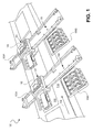
- FIG. 1 shows a fluid-ejection assembly 100, according to an embodiment of the invention.
- the fluid-ejection assembly 100 includes a first array of fluid-ejection mechanisms 102, a first drive mechanism 106A, a first service station 108A, a second array of fluid-ejection mechanisms 104, a second drive mechanism 106B, and a second service station 108B.
- the drive mechanisms 106A and 106B are collectively referred to as the drive mechanisms 106, and the service stations 108A and 108B are collectively referred to as the service stations 108.
- the fluid-ejection assembly 100 can also include a moveable media belt 110, on which media 112 is moved for fluid ejection thereon by the first array 102 or the second array 104.
- the arrays 102 and 104 can in one embodiment be arrays of inkjet printheads, such that the assembly 100 is an inkjet assembly.
- the fluid-ejection assembly 100 preferably is a drop-on-demand fluid-ejection assembly, as opposed to a continuous fluid-ejection assembly commonly referred to as continuous inkjet (CIJ).
- CIJ continuous inkjet
- a drop-on-demand assembly ejects ink as it is to be used to form an image on the media 112, whereas a continuous inkjet assembly continuously ejects ink.
- the continuously ejected ink is deflected to either impact the media 112 or be directed away from the media 112, in accordance with the image to be formed on the media 112.
- Drop-on-demand fluid-ejection assemblies include thermal inkjet (TIJ) and piezo inkjet (PIJ) technologies.
- TIJ technology generally utilizes heat to eject ink
- PIJ technology generally utilizes pressure to eject ink.
- the first array 102 is connected with the first drive mechanism 106A.
- the first drive mechanism 106A is moved relative to the first service station 108A and a movable media belt 110 such that the first drive mechanism 106A can move the first array 102 between a first position 152 and a second position 154.
- the first position 152 the first array 102 is able to eject fluid onto media 112 traversing in a direction indicated by the arrow 114 on the movable media belt 110, while the array 102 remains stationary, such that the array 102 can be referred to as being normally stationary.
- the first array 102 is thus positioned over the belt 110 in the first position 152 for fluid ejection, such that the belt 110 moves, with the media 112 thereon, past the first array 102.
- the first array 102 is at the first service station 108A, for servicing the first array 102.
- the second array 104 is connected with the second drive mechanism 106B.
- the second drive mechanism 106B is moved relative to the second service station 108B and the movable media belt 110 such that the second drive mechanism 106B can move the second array 104 between and a third position 156 and a fourth position 158.
- the third position 156 the second array 104 is able to eject fluid onto the media 112 traversing in a direction indicated by the arrow 114 on the movable media belt 110, while the array 104 remains stationary, such that the array 104 can be referred to as being normally stationary.
- the second array 104 is thus positioned over the belt 110 in the third position 156 for fluid ejection, such that the belt 110 moves, with the media 112 thereon, past the second array 104.
- the fourth position 158 the second array 104 is at the second service station 108B, for servicing the second array 104.
- the array 102 moves via the drive mechanism 106A so that it is positioned at the first service station 108A.
- the array of fluid-ejection mechanisms 104 moves via the drive mechanism 106B so that it is positioned at the second service station 108B.
- the array 102 is ejecting fluid on the media 112 moving on the belt 110
- the array 104 is not ejecting fluid on the media 112.
- the array 104 is ejecting fluid on the media 112 moving on the belt 110, the array 102 is not ejecting fluid on the media 112.
- fluid ejection may continue onto the media 112 without having to stop movement of the media 112 when either of the arrays 102 and 104 has to be serviced.
- the media 112, as being moved on the belt 110, does not have become aware that the array 104 has substituted for the array 102, and vice-versa. That is, the media 112 does not have to slow down when either of the arrays 102 and 104 is serviced.
- the array 104 is first moved to the third position 156, so that it can begin ejecting fluid onto the media 112 before the array 102 stops ejecting fluid and is moved to the service station 108A.
- the array 102 is first moved to the first position 152, so that it can begin ejecting fluid onto the media before the array 104 stops ejecting fluid and is moved to the service station 108B.
- the array 104 thus ejects fluid in place of the array 102 while the array 102 is being serviced, and the array 102 ejects fluid in place of the array 104 while the array 104 is being serviced.
- the drive mechanisms 106 include those components, such as motors, rails, and so on, which enable the arrays 102 and 104 to be moved.
- the drive mechanisms 106A and 106B are automatic linear actuators.
- the drive mechanisms 106A and 106B are manually operated bearing rails.
- the stations 108 include those components, such as wipers, and so on, those enable the arrays 102 and 104 to be serviced either manually or automatically.
- the media 112 can be cut-sheet paper. Alternatively, the media 112 can be continuous web paper, corrugated boxes, labels, and the like, or another type of media.
- the fluid-ejection assembly 100 is pictured in FIG. 1 and has been described as having a first array of fluid-ejection mechanisms 102 and a second array of fluid-ejecting mechanisms 104.
- FIG. 2 shows an array of fluid-ejection mechanisms 200, according to an embodiment of the invention.
- the array 200 may implement either or both of the first array of fluid-ejection mechanisms 102 and the second array of fluid-ejection mechanisms 104 of FIG. 1.
- the array 200 includes fluid-ejection mechanisms 202A, 202B, 202C, ..., 202N, where N is the total number of the fluid-ejection mechanisms 202.
- N 4 and the fluid-ejection mechanisms 202 eject different spot color inks, such as red, blue, purple, orange, and the like.
- N 4 and the fluid-ejection mechanism 202 eject differently colored inks in accordance with a color model, such as the cyan-magenta-yellow-black (CMYK) color model.
- the number of the mechanisms 202 may also be other than four.
- FIG. 3 shows an array of fluid-ejection mechanisms 300, according to another embodiment of the invention.
- the array 300 may implement either or both of the first array of fluid-ejection mechanisms 102 and the second array of fluid-ejection mechanisms 104 of FIG. 1.
- the array 300 includes fluid-ejection mechanisms 302A, 302B, 302C, ..., 302N, where N is the total number of fluid-ejection mechanisms.
- the fluid-ejection mechanisms 302 are aligned such that they are staggered relative to each other.
- N 5 and the fluid-ejection mechanisms 302 are all inkjet printheads ejecting black ink.
- the number of the mechanisms 302 may also be other than five.
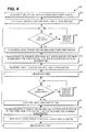
- FIG. 4 is a flowchart describing a method 400 for operating the fluid-ejection assembly of FIG. 1, according to an embodiment of the invention.
- the method 400 may be implemented as a computer program on a computer-readable medium.
- the computer-readable medium may be a volatile or a non-volatile medium.
- the medium may also be a magnetic medium, like a floppy disk or a hard disk drive, an optical medium, like a compact disc (CD)-type medium or a digital versatile disc (DVD)-type medium, and/or a semiconductor medium, like a flash memory or a dynamic random access memory (DRAM).
- CD compact disc
- DVD digital versatile disc
- DRAM dynamic random access memory
- the method 400 begins when the first array of fluid-ejection mechanisms 102 is moved in the first position 152 (402), such as by the first drive mechanism 106A.
- the first array 102 then initiates ejection of fluid onto the media 112 from the first position 152 (404). Where the first array 102 does is not to be serviced (406), then the first array 102 continues to eject fluid (408).
- the second array of fluid-ejection mechanisms 104 is moved in the third position 156 (410), such as by the second drive mechanism 106B. Ejection of fluid from the first array 102 is terminated, and ejection of fluid from the second array 104 is initiated from the third position 156 (412).
- the first array 102 is moved to the second position 154 at the first service station 108A (414), such as by the first drive mechanism 106A, and the first array 102 is serviced (416).
- the second array 104 continues to eject fluid (420).
- the first array 102 is moved back in the first position 152 (422), such as by the first drive mechanism 106A. Ejection of fluid from the second array 104 is terminated, and ejection of fluid from the first array 104 is again initiated from the first position 152 (424).
- the second array 104 is moved to the fourth position 158 at the second service station 108B (426), such as by the second drive mechanism 106B, and the second array 104 is serviced (428).
- the method 400 then repeats at 406 as has been described, until the fluid-ejection, or print, job is finished.
- servicing is manually triggered by an operator.
- An operator may, for instance, trigger servicing upon determining that an array of fluid ejection mechanisms is not properly ejecting fluid onto media 112.
- servicing is automatically triggered, via, for instance, machine-vision inspection detecting that an array of fluid ejection mechanisms is not properly ejecting fluid onto media 112.
- servicing may be automatically triggered at predetermined intervals.
- FIG. 5 shows a block diagram of a fluid-ejection device 500, according to an embodiment of the invention.
- the fluid-ejection device 500 includes the belt 110 on which media moves, as has been described.
- the fluid-ejection device 500 also includes the array of fluid-ejection mechanisms 102, and the array of fluid-ejection mechanisms 104, as have also been described.
- the fluid-ejection device 500 includes the drive mechanisms 106, as have been described.
- the device 500 may include other components, in addition to and/or in lieu of those depicted in FIG. 5, such as, for example, the service stations 108 of FIG. 1.
- the fluid-ejection device 500 is operable as has been described in the preceding sections of the detailed description. For instance, where the array 102 is ejecting fluid, the array 104 is not, and vice-versa. Where the arrays 102 and 104 are arrays of inkjet-printing mechanisms, such as inkjet printheads or pens, the fluid-ejection device 500 is specifically an inkjet-printing device, such as an inkjet printer.
Landscapes
- Ink Jet (AREA)
Abstract
Description
- The present invention relates to a fluid ejection assembly.
- Inkjet printers generally operate by ejecting ink onto media, such as paper. One type of inkjet printer utilizes an array of inkjet printheads to eject ink onto media. The inkjet printheads within the array are normally immobile relative to each other, and are typically arranged either in-line along the direction of printing or in a staggered fashion relative to each other. As media is moved past the array of inkjet printheads, the printheads accordingly eject ink onto the media. This type of inkjet printer is typically used in industrial setting.
- Printing is interrupted when any of the printheads within the array need servicing. Servicing is generally defined as tasks performed to maintain a printhead in proper operating condition such as wiping debris from the printhead, ejecting ink from the printhead, and capping the printhead when not in use. Replacing a printhead that has permanently failed with a properly operating printhead also falls under the general definition of servicing. Unfortunately, interrupting printing to service the array of inkjet printheads delays completion of a print job and can waste significant amounts of ink and media.
- The present invention seeks to provide an improved fluid ejection assembly.
- According to an aspect of the present invention, there is provided a fluid ejection assembly as specified in claim 1.
- Embodiments of the present invention are described below, by way of example only, with reference to the accompanying drawings in which:
- FIG. 1 is a perspective view of a fluid-ejection assembly, according to an embodiment of the invention.
- FIG. 2 is a schematic diagram of an array of fluid-ejection mechanisms, according to an embodiment of the invention.
- FIG. 3 is a schematic diagram of an array of fluid-ejection mechanisms, according to another embodiment of the invention.
- FIG. 4 is a flowchart describing a method for operating the fluid-ejection assembly of FIG. 1, according to an embodiment of the invention.
- FIG. 5 is a block diagram of a fluid-ejection device, according to an embodiment of the invention.
-
- In the following detailed description of exemplary embodiments of the invention, reference is made to the accompanying drawings that form a part hereof, and in which is shown by way of illustration specific exemplary embodiments in which the invention may be practiced. These embodiments are described in sufficient detail to enable those skilled in the art to practice the invention. Other embodiments may be utilized, and logical, mechanical, and other changes may be made without departing from the scope of the claims. The following detailed description is, therefore, not to be taken in a limiting sense, and the scope of the invention is defined only by the appended claims.
- FIG. 1 shows a fluid-
ejection assembly 100, according to an embodiment of the invention. The fluid-ejection assembly 100 includes a first array of fluid-ejection mechanisms 102, afirst drive mechanism 106A, a first service station 108A, a second array of fluid-ejection mechanisms 104, asecond drive mechanism 106B, and asecond service station 108B. Thedrive mechanisms service stations 108A and 108B are collectively referred to as the service stations 108. The fluid-ejection assembly 100 can also include amoveable media belt 110, on whichmedia 112 is moved for fluid ejection thereon by thefirst array 102 or thesecond array 104. - The
arrays assembly 100 is an inkjet assembly. The fluid-ejection assembly 100 preferably is a drop-on-demand fluid-ejection assembly, as opposed to a continuous fluid-ejection assembly commonly referred to as continuous inkjet (CIJ). A drop-on-demand assembly ejects ink as it is to be used to form an image on themedia 112, whereas a continuous inkjet assembly continuously ejects ink. The continuously ejected ink is deflected to either impact themedia 112 or be directed away from themedia 112, in accordance with the image to be formed on themedia 112. Drop-on-demand fluid-ejection assemblies include thermal inkjet (TIJ) and piezo inkjet (PIJ) technologies. TIJ technology generally utilizes heat to eject ink, whereas PIJ technology generally utilizes pressure to eject ink. - The
first array 102 is connected with thefirst drive mechanism 106A. Thefirst drive mechanism 106A is moved relative to the first service station 108A and amovable media belt 110 such that thefirst drive mechanism 106A can move thefirst array 102 between afirst position 152 and asecond position 154. In thefirst position 152, thefirst array 102 is able to eject fluid ontomedia 112 traversing in a direction indicated by thearrow 114 on themovable media belt 110, while thearray 102 remains stationary, such that thearray 102 can be referred to as being normally stationary. Thefirst array 102 is thus positioned over thebelt 110 in thefirst position 152 for fluid ejection, such that thebelt 110 moves, with themedia 112 thereon, past thefirst array 102. In thesecond position 154, thefirst array 102 is at the first service station 108A, for servicing thefirst array 102. - The
second array 104 is connected with thesecond drive mechanism 106B. Thesecond drive mechanism 106B is moved relative to thesecond service station 108B and themovable media belt 110 such that thesecond drive mechanism 106B can move thesecond array 104 between and athird position 156 and afourth position 158. In thethird position 156, thesecond array 104 is able to eject fluid onto themedia 112 traversing in a direction indicated by thearrow 114 on themovable media belt 110, while thearray 104 remains stationary, such that thearray 104 can be referred to as being normally stationary. Thesecond array 104 is thus positioned over thebelt 110 in thethird position 156 for fluid ejection, such that thebelt 110 moves, with themedia 112 thereon, past thesecond array 104. In thefourth position 158, thesecond array 104 is at thesecond service station 108B, for servicing thesecond array 104. - Thus, when the array of fluid-
ejection mechanisms 102 is to be serviced, thearray 102 moves via thedrive mechanism 106A so that it is positioned at the first service station 108A. Similarly, when the array of fluid-ejection mechanisms 104 is to be serviced, thearray 104 moves via thedrive mechanism 106B so that it is positioned at thesecond service station 108B. When thearray 102 is ejecting fluid on themedia 112 moving on thebelt 110, thearray 104 is not ejecting fluid on themedia 112. Similarly, when thearray 104 is ejecting fluid on themedia 112 moving on thebelt 110, thearray 102 is not ejecting fluid on themedia 112. - As a result, fluid ejection may continue onto the
media 112 without having to stop movement of themedia 112 when either of thearrays media 112, as being moved on thebelt 110, does not have become aware that thearray 104 has substituted for thearray 102, and vice-versa. That is, themedia 112 does not have to slow down when either of thearrays array 102 is to be serviced, thearray 104 is first moved to thethird position 156, so that it can begin ejecting fluid onto themedia 112 before thearray 102 stops ejecting fluid and is moved to the service station 108A. Similarly, when thearray 104 is to be serviced, thearray 102 is first moved to thefirst position 152, so that it can begin ejecting fluid onto the media before thearray 104 stops ejecting fluid and is moved to theservice station 108B. Thearray 104 thus ejects fluid in place of thearray 102 while thearray 102 is being serviced, and thearray 102 ejects fluid in place of thearray 104 while thearray 104 is being serviced. - The drive mechanisms 106 include those components, such as motors, rails, and so on, which enable the
arrays drive mechanisms drive mechanisms arrays media 112 can be cut-sheet paper. Alternatively, themedia 112 can be continuous web paper, corrugated boxes, labels, and the like, or another type of media. - The fluid-
ejection assembly 100 is pictured in FIG. 1 and has been described as having a first array of fluid-ejection mechanisms 102 and a second array of fluid-ejecting mechanisms 104. Alternatively, there can be more than two arrays of fluid-ejecting mechanisms. Having more than two arrays means that when any one array of fluid-ejection mechanisms is to be serviced, more than one array remains to take over fluid-ejection responsibilities. - FIG. 2 shows an array of fluid-
ejection mechanisms 200, according to an embodiment of the invention. Thearray 200 may implement either or both of the first array of fluid-ejection mechanisms 102 and the second array of fluid-ejection mechanisms 104 of FIG. 1. Thearray 200 includes fluid-ejection mechanisms - FIG. 3 shows an array of fluid-
ejection mechanisms 300, according to another embodiment of the invention. Thearray 300 may implement either or both of the first array of fluid-ejection mechanisms 102 and the second array of fluid-ejection mechanisms 104 of FIG. 1. Thearray 300 includes fluid-ejection mechanisms - FIG. 4 is a flowchart describing a
method 400 for operating the fluid-ejection assembly of FIG. 1, according to an embodiment of the invention. Themethod 400 may be implemented as a computer program on a computer-readable medium. The computer-readable medium may be a volatile or a non-volatile medium. The medium may also be a magnetic medium, like a floppy disk or a hard disk drive, an optical medium, like a compact disc (CD)-type medium or a digital versatile disc (DVD)-type medium, and/or a semiconductor medium, like a flash memory or a dynamic random access memory (DRAM). - The
method 400 begins when the first array of fluid-ejection mechanisms 102 is moved in the first position 152 (402), such as by thefirst drive mechanism 106A. Thefirst array 102 then initiates ejection of fluid onto themedia 112 from the first position 152 (404). Where thefirst array 102 does is not to be serviced (406), then thefirst array 102 continues to eject fluid (408). - Once the
first array 102 is to be serviced (406), however, the second array of fluid-ejection mechanisms 104 is moved in the third position 156 (410), such as by thesecond drive mechanism 106B. Ejection of fluid from thefirst array 102 is terminated, and ejection of fluid from thesecond array 104 is initiated from the third position 156 (412). Thefirst array 102 is moved to thesecond position 154 at the first service station 108A (414), such as by thefirst drive mechanism 106A, and thefirst array 102 is serviced (416). - Where the
second array 104 does is not to be serviced (418), then thesecond array 104 continues to eject fluid (420). Once thesecond array 104 is to be serviced (418), however, thefirst array 102 is moved back in the first position 152 (422), such as by thefirst drive mechanism 106A. Ejection of fluid from thesecond array 104 is terminated, and ejection of fluid from thefirst array 104 is again initiated from the first position 152 (424). Thesecond array 104 is moved to thefourth position 158 at thesecond service station 108B (426), such as by thesecond drive mechanism 106B, and thesecond array 104 is serviced (428). Themethod 400 then repeats at 406 as has been described, until the fluid-ejection, or print, job is finished. - It is noted that in one embodiment of the invention, servicing is manually triggered by an operator. An operator may, for instance, trigger servicing upon determining that an array of fluid ejection mechanisms is not properly ejecting fluid onto
media 112. In another embodiment of the invention, servicing is automatically triggered, via, for instance, machine-vision inspection detecting that an array of fluid ejection mechanisms is not properly ejecting fluid ontomedia 112. Alternatively, servicing may be automatically triggered at predetermined intervals. - FIG. 5 shows a block diagram of a fluid-
ejection device 500, according to an embodiment of the invention. The fluid-ejection device 500 includes thebelt 110 on which media moves, as has been described. The fluid-ejection device 500 also includes the array of fluid-ejection mechanisms 102, and the array of fluid-ejection mechanisms 104, as have also been described. Finally, the fluid-ejection device 500 includes the drive mechanisms 106, as have been described. Thedevice 500 may include other components, in addition to and/or in lieu of those depicted in FIG. 5, such as, for example, the service stations 108 of FIG. 1. - The fluid-
ejection device 500 is operable as has been described in the preceding sections of the detailed description. For instance, where thearray 102 is ejecting fluid, thearray 104 is not, and vice-versa. Where thearrays ejection device 500 is specifically an inkjet-printing device, such as an inkjet printer. - Other applications and uses of embodiments of the invention, besides those described herein, are amenable to at least some embodiments. This application is intended to cover any such adaptations or variations.
- The disclosures in United States patent application no. 10/693,777, from which this application claims priority, and in the abstract accompanying this application are incorporated herein by reference.
Claims (9)
- A fluid ejection assembly (100) including:a first array of fluid-ejection mechanisms (102) operable to eject fluid onto media;a first service station (108A) operable to service the first array of fluid-ejection mechanisms;a second array of fluid-ejection mechanisms (104) operable to eject fluid onto the media;a second service station (108B) operable to service the second array of fluid-ejection mechanisms;a first drive mechanism (106A) operable to move the first array of fluid-ejection mechanisms between a first position to eject fluid onto the media and a second position at the first service station while the second array of fluid-ejection mechanisms; and,a second drive mechanism (106B) operable to move the second array of fluid-ejection mechanisms between a third position to eject fluid onto the media and a fourth position at the second service station while the first array of fluid-ejection mechanisms ejects fluid onto the media in place of the second array of fluid-ejection mechanism.
- An assembly as in claim 1, wherein each of the first array of fluid-ejection mechanisms and the second array of fluid-ejection mechanisms remains stationary while ejecting fluid onto the media, such that the media moves past one of the first and the second arrays of fluid-ejection mechanisms.
- An assembly as in claim 2, including a belt (110) on which the media is moved past one of the first and the second arrays of fluid-ejection mechanisms.
- An assembly as in claim 1, 2 or 3, wherein while the first array of fluid-ejection mechanisms is to be serviced at the first service station in the second position, the second array of fluid-ejection mechanisms is to eject fluid onto the media in the third position.
- An assembly as in any preceding claim, wherein while the second array of fluid-ejection mechanisms is to be serviced at the second service in the fourth position, the first array of fluid-ejection mechanisms is to eject fluid onto the media in the first position.
- An assembly as in any preceding claim, wherein the first array of fluid-ejection mechanisms and the second array of fluid-ejection mechanisms each includes an array of inkjet printheads for ejecting ink onto the media.
- An assembly as in any preceding claim, wherein the first array of fluid-ejection mechanisms and the second array of fluid-ejection mechanisms each in use eject different spot color inks.
- An assembly as in any preceding claim, wherein the first array of fluid-ejection mechanisms and the second array of fluid-ejection mechanisms each in use eject differently colored inks in accordance with a color model.
- An assembly as in claim 8, wherein the color model is a cyan-magenta-yellow-black (CMYK) color model.
Applications Claiming Priority (2)
| Application Number | Priority Date | Filing Date | Title |
|---|---|---|---|
| US693777 | 2003-10-25 | ||
| US10/693,777 US7086716B2 (en) | 2003-10-25 | 2003-10-25 | Fluid-ejection assembly |
Publications (1)
| Publication Number | Publication Date |
|---|---|
| EP1525984A1 true EP1525984A1 (en) | 2005-04-27 |
Family
ID=34394599
Family Applications (1)
| Application Number | Title | Priority Date | Filing Date |
|---|---|---|---|
| EP04255774A Withdrawn EP1525984A1 (en) | 2003-10-25 | 2004-09-22 | Fluid-ejection assembly including several service stations |
Country Status (2)
| Country | Link |
|---|---|
| US (1) | US7086716B2 (en) |
| EP (1) | EP1525984A1 (en) |
Cited By (3)
| Publication number | Priority date | Publication date | Assignee | Title |
|---|---|---|---|---|
| WO2008056241A3 (en) * | 2006-11-08 | 2008-07-17 | Antonio Maccari | Plant and method for decoration by means of ink-jet technology |
| EP3248799A1 (en) * | 2016-05-27 | 2017-11-29 | Riso Kagaku Corporation | Inkjet printing apparatus for web being print medium |
| EP3653392A1 (en) * | 2018-11-13 | 2020-05-20 | Notion Systems GmbH | Pick-up device for displaceable arrangement of a printhead module frame |
Families Citing this family (16)
| Publication number | Priority date | Publication date | Assignee | Title |
|---|---|---|---|---|
| US20050116976A1 (en) * | 2003-05-20 | 2005-06-02 | Salacz Philipp O.I. | Method of inkjet printing in high efficiency production of hygienic articles |
| JP4035096B2 (en) * | 2003-08-29 | 2008-01-16 | 松下電器産業株式会社 | Inkjet recording device |
| JP4347187B2 (en) * | 2004-02-13 | 2009-10-21 | セイコーエプソン株式会社 | Droplet ejection device, electro-optical device manufacturing method, electro-optical device, and electronic apparatus |
| US20060044345A1 (en) * | 2004-08-27 | 2006-03-02 | Morgan Jones | Multimode printhead |
| US7556334B2 (en) | 2004-11-04 | 2009-07-07 | Applied Materials, Inc. | Methods and apparatus for aligning print heads |
| ATE528140T1 (en) * | 2004-12-03 | 2011-10-15 | Fujifilm Dimatix Inc | INKJET PRINTING DEVICE WITH IMPROVED PRINTHEAD MAINTENANCE |
| KR100727987B1 (en) * | 2005-09-28 | 2007-06-13 | 삼성전자주식회사 | Hybrid inkjet head and image forming apparatus having the wiping device of the inkjet head |
| US20100066779A1 (en) * | 2006-11-28 | 2010-03-18 | Hanan Gothait | Method and system for nozzle compensation in non-contact material deposition |
| EP2094496B1 (en) * | 2006-11-28 | 2012-06-27 | Xjet Ltd. | Inkjet printing method |
| KR20080104509A (en) * | 2007-05-28 | 2008-12-03 | 삼성전자주식회사 | Inkjet head cleaning apparatus and inkjet image forming apparatus having the same |
| JP2009279887A (en) * | 2008-05-26 | 2009-12-03 | Brother Ind Ltd | Printer |
| JP2009279888A (en) * | 2008-05-26 | 2009-12-03 | Brother Ind Ltd | Printing device |
| WO2010071644A1 (en) | 2008-12-17 | 2010-06-24 | Hewlett-Packard Development Company, L.P. | Print head array |
| US9061531B2 (en) * | 2013-11-15 | 2015-06-23 | Memjet Technology Ltd. | Modular printer having narrow print zone |
| US10926541B2 (en) * | 2016-10-17 | 2021-02-23 | Hewlett-Packard Development Company, L.P. | Printing device |
| KR102520976B1 (en) * | 2021-03-30 | 2023-04-12 | (주)에스티아이 | Method of controlling inkjet printing process |
Citations (3)
| Publication number | Priority date | Publication date | Assignee | Title |
|---|---|---|---|---|
| JP2000218884A (en) * | 1999-02-02 | 2000-08-08 | Canon Inc | Recording device |
| JP2002059559A (en) * | 2000-08-14 | 2002-02-26 | Casio Comput Co Ltd | Color inkjet printer |
| WO2003074277A1 (en) * | 2002-03-07 | 2003-09-12 | Fuji Xerox Co., Ltd. | Ink-jet line printer and image forming device using it |
Family Cites Families (11)
| Publication number | Priority date | Publication date | Assignee | Title |
|---|---|---|---|---|
| JP2731003B2 (en) * | 1988-12-06 | 1998-03-25 | キヤノン株式会社 | Liquid jet recording device |
| US5587730A (en) * | 1994-09-30 | 1996-12-24 | Xerox Corporation | Redundant full width array thermal ink jet printing for improved reliability |
| US5838343A (en) * | 1995-05-12 | 1998-11-17 | Moore Business Forms, Inc. | Backup print cartridge for bank of ink-jet printing cartridges |
| US5917508A (en) * | 1996-03-20 | 1999-06-29 | Diagraph Corporation | Piezoelectric ink jet printing system |
| US5984455A (en) * | 1997-11-04 | 1999-11-16 | Lexmark International, Inc. | Ink jet printing apparatus having primary and secondary nozzles |
| US6076910A (en) * | 1997-11-04 | 2000-06-20 | Lexmark International, Inc. | Ink jet printing apparatus having redundant nozzles |
| AUPP996099A0 (en) * | 1999-04-23 | 1999-05-20 | Silverbrook Research Pty Ltd | A method and apparatus(sprint01) |
| US6244688B1 (en) * | 1999-07-20 | 2001-06-12 | Hewlett-Packard Company | Pen stagger in color inkjet hard copy apparatus |
| US6536883B2 (en) * | 2001-02-16 | 2003-03-25 | Eastman Kodak Company | Continuous ink-jet printer having two dimensional nozzle array and method of increasing ink drop density |
| US6655770B2 (en) * | 2001-05-02 | 2003-12-02 | Hewlett-Packard Development Company, L.P. | Apparatus and method for printing with showerhead groups |
| US6783209B2 (en) * | 2002-06-03 | 2004-08-31 | Hewlett-Packard Development Company, L.P. | Multiple print bar approach to pen health and fiber management |
-
2003
- 2003-10-25 US US10/693,777 patent/US7086716B2/en not_active Expired - Lifetime
-
2004
- 2004-09-22 EP EP04255774A patent/EP1525984A1/en not_active Withdrawn
Patent Citations (4)
| Publication number | Priority date | Publication date | Assignee | Title |
|---|---|---|---|---|
| JP2000218884A (en) * | 1999-02-02 | 2000-08-08 | Canon Inc | Recording device |
| JP2002059559A (en) * | 2000-08-14 | 2002-02-26 | Casio Comput Co Ltd | Color inkjet printer |
| WO2003074277A1 (en) * | 2002-03-07 | 2003-09-12 | Fuji Xerox Co., Ltd. | Ink-jet line printer and image forming device using it |
| EP1462264A1 (en) * | 2002-03-07 | 2004-09-29 | Fuji Xerox Co., Ltd | Ink-jet line printer and image forming device using it |
Non-Patent Citations (2)
| Title |
|---|
| PATENT ABSTRACTS OF JAPAN vol. 2000, no. 11 3 January 2001 (2001-01-03) * |
| PATENT ABSTRACTS OF JAPAN vol. 2002, no. 06 4 June 2002 (2002-06-04) * |
Cited By (4)
| Publication number | Priority date | Publication date | Assignee | Title |
|---|---|---|---|---|
| WO2008056241A3 (en) * | 2006-11-08 | 2008-07-17 | Antonio Maccari | Plant and method for decoration by means of ink-jet technology |
| EP3248799A1 (en) * | 2016-05-27 | 2017-11-29 | Riso Kagaku Corporation | Inkjet printing apparatus for web being print medium |
| US10105977B2 (en) | 2016-05-27 | 2018-10-23 | Riso Kagaku Corporation | Inkjet printing apparatus for web being print medium |
| EP3653392A1 (en) * | 2018-11-13 | 2020-05-20 | Notion Systems GmbH | Pick-up device for displaceable arrangement of a printhead module frame |
Also Published As
| Publication number | Publication date |
|---|---|
| US20050088479A1 (en) | 2005-04-28 |
| US7086716B2 (en) | 2006-08-08 |
Similar Documents
| Publication | Publication Date | Title |
|---|---|---|
| US7086716B2 (en) | Fluid-ejection assembly | |
| US7845786B2 (en) | Image forming apparatus and ejection state determination method | |
| KR940007478B1 (en) | Inkjet recording method and color inkjet recording apparatus for carrying out this | |
| US7360887B2 (en) | Image forming apparatus and method | |
| US7448706B2 (en) | Image forming apparatus and method | |
| JP4032360B2 (en) | Inkjet recording apparatus and ejection failure detection method | |
| JP3838251B2 (en) | Inkjet recording apparatus and ejection failure detection method | |
| US7654635B2 (en) | Media print system | |
| JP6483037B2 (en) | Control method for reducing printhead damage and contamination | |
| JP2005096447A (en) | Inkjet recording apparatus and discharge fault detecting method | |
| JP2005074956A (en) | Image forming apparatus and method | |
| EP1083051B1 (en) | Separarate print head wiping operation dependent upon print head direction to reduce inkjet printer size | |
| JP3483410B2 (en) | Ink jet recording device | |
| US20070046757A1 (en) | Spitting device for inkjet head of image forming apparatus | |
| US7367651B2 (en) | Inkjet printing head and inkjet printer using the same | |
| JP3815620B2 (en) | Image recording device | |
| JP2005104037A (en) | Image forming device and recording control method | |
| US20100177139A1 (en) | Inkjet image forming apparatus | |
| JP3807429B2 (en) | Image forming apparatus and droplet ejection control method | |
| JP2008049572A (en) | Inkjet recorder | |
| JP2006142840A (en) | Inkjet recording device and preliminary ejection controlling method | |
| JP5850667B2 (en) | Inkjet recording apparatus and inkjet recording method | |
| US20050237354A1 (en) | Selection of printheads via enable lines | |
| US20050122374A1 (en) | Inkjet printer | |
| JP4042123B2 (en) | Image forming apparatus and droplet ejection control method |
Legal Events
| Date | Code | Title | Description |
|---|---|---|---|
| PUAI | Public reference made under article 153(3) epc to a published international application that has entered the european phase |
Free format text: ORIGINAL CODE: 0009012 |
|
| AK | Designated contracting states |
Kind code of ref document: A1 Designated state(s): AT BE BG CH CY CZ DE DK EE ES FI FR GB GR HU IE IT LI LU MC NL PL PT RO SE SI SK TR |
|
| AX | Request for extension of the european patent |
Extension state: AL HR LT LV MK |
|
| RIN1 | Information on inventor provided before grant (corrected) |
Inventor name: BERARDELLI, DAVID Inventor name: MURCIA, ANTONI Inventor name: VIVES, JUAN C. Inventor name: SAMII, MOHAMMAD M. Inventor name: COURIAN, KENNETH J. Inventor name: ESCOBEDO, VICTOR T. Inventor name: BEZENEK, MYRON A. Inventor name: HOCK, SCOTT Inventor name: STEINFIELD, STEVE |
|
| 17P | Request for examination filed |
Effective date: 20050801 |
|
| AKX | Designation fees paid |
Designated state(s): DE FR GB |
|
| GRAP | Despatch of communication of intention to grant a patent |
Free format text: ORIGINAL CODE: EPIDOSNIGR1 |
|
| STAA | Information on the status of an ep patent application or granted ep patent |
Free format text: STATUS: THE APPLICATION IS DEEMED TO BE WITHDRAWN |
|
| 18D | Application deemed to be withdrawn |
Effective date: 20060704 |