EP1525976A2 - Bottom closing device in a bag making machine - Google Patents
Bottom closing device in a bag making machine Download PDFInfo
- Publication number
- EP1525976A2 EP1525976A2 EP04022402A EP04022402A EP1525976A2 EP 1525976 A2 EP1525976 A2 EP 1525976A2 EP 04022402 A EP04022402 A EP 04022402A EP 04022402 A EP04022402 A EP 04022402A EP 1525976 A2 EP1525976 A2 EP 1525976A2
- Authority
- EP
- European Patent Office
- Prior art keywords
- bag
- rotatable part
- bag machine
- cylinder
- machine
- Prior art date
- Legal status (The legal status is an assumption and is not a legal conclusion. Google has not performed a legal analysis and makes no representation as to the accuracy of the status listed.)
- Granted
Links
Images

Classifications
-
- B—PERFORMING OPERATIONS; TRANSPORTING
- B31—MAKING ARTICLES OF PAPER, CARDBOARD OR MATERIAL WORKED IN A MANNER ANALOGOUS TO PAPER; WORKING PAPER, CARDBOARD OR MATERIAL WORKED IN A MANNER ANALOGOUS TO PAPER
- B31B—MAKING CONTAINERS OF PAPER, CARDBOARD OR MATERIAL WORKED IN A MANNER ANALOGOUS TO PAPER
- B31B70/00—Making flexible containers, e.g. envelopes or bags
-
- B—PERFORMING OPERATIONS; TRANSPORTING
- B31—MAKING ARTICLES OF PAPER, CARDBOARD OR MATERIAL WORKED IN A MANNER ANALOGOUS TO PAPER; WORKING PAPER, CARDBOARD OR MATERIAL WORKED IN A MANNER ANALOGOUS TO PAPER
- B31B—MAKING CONTAINERS OF PAPER, CARDBOARD OR MATERIAL WORKED IN A MANNER ANALOGOUS TO PAPER
- B31B70/00—Making flexible containers, e.g. envelopes or bags
- B31B70/02—Feeding or positioning sheets, blanks or webs
- B31B70/022—Holders for feeding or positioning sheets or webs
- B31B70/024—Rotating holders, e.g. star wheels, drums
-
- B—PERFORMING OPERATIONS; TRANSPORTING
- B31—MAKING ARTICLES OF PAPER, CARDBOARD OR MATERIAL WORKED IN A MANNER ANALOGOUS TO PAPER; WORKING PAPER, CARDBOARD OR MATERIAL WORKED IN A MANNER ANALOGOUS TO PAPER
- B31B—MAKING CONTAINERS OF PAPER, CARDBOARD OR MATERIAL WORKED IN A MANNER ANALOGOUS TO PAPER
- B31B2150/00—Flexible containers made from sheets or blanks, e.g. from flattened tubes
-
- B—PERFORMING OPERATIONS; TRANSPORTING
- B31—MAKING ARTICLES OF PAPER, CARDBOARD OR MATERIAL WORKED IN A MANNER ANALOGOUS TO PAPER; WORKING PAPER, CARDBOARD OR MATERIAL WORKED IN A MANNER ANALOGOUS TO PAPER
- B31B—MAKING CONTAINERS OF PAPER, CARDBOARD OR MATERIAL WORKED IN A MANNER ANALOGOUS TO PAPER
- B31B2150/00—Flexible containers made from sheets or blanks, e.g. from flattened tubes
- B31B2150/001—Flexible containers made from sheets or blanks, e.g. from flattened tubes with square or cross bottom
- B31B2150/0012—Flexible containers made from sheets or blanks, e.g. from flattened tubes with square or cross bottom having their openings facing in the direction of movement
-
- B—PERFORMING OPERATIONS; TRANSPORTING
- B31—MAKING ARTICLES OF PAPER, CARDBOARD OR MATERIAL WORKED IN A MANNER ANALOGOUS TO PAPER; WORKING PAPER, CARDBOARD OR MATERIAL WORKED IN A MANNER ANALOGOUS TO PAPER
- B31B—MAKING CONTAINERS OF PAPER, CARDBOARD OR MATERIAL WORKED IN A MANNER ANALOGOUS TO PAPER
- B31B2160/00—Shape of flexible containers
- B31B2160/10—Shape of flexible containers rectangular and flat, i.e. without structural provision for thickness of contents
-
- B—PERFORMING OPERATIONS; TRANSPORTING
- B31—MAKING ARTICLES OF PAPER, CARDBOARD OR MATERIAL WORKED IN A MANNER ANALOGOUS TO PAPER; WORKING PAPER, CARDBOARD OR MATERIAL WORKED IN A MANNER ANALOGOUS TO PAPER
- B31B—MAKING CONTAINERS OF PAPER, CARDBOARD OR MATERIAL WORKED IN A MANNER ANALOGOUS TO PAPER
- B31B2160/00—Shape of flexible containers
- B31B2160/20—Shape of flexible containers with structural provision for thickness of contents
-
- B—PERFORMING OPERATIONS; TRANSPORTING
- B31—MAKING ARTICLES OF PAPER, CARDBOARD OR MATERIAL WORKED IN A MANNER ANALOGOUS TO PAPER; WORKING PAPER, CARDBOARD OR MATERIAL WORKED IN A MANNER ANALOGOUS TO PAPER
- B31B—MAKING CONTAINERS OF PAPER, CARDBOARD OR MATERIAL WORKED IN A MANNER ANALOGOUS TO PAPER
- B31B70/00—Making flexible containers, e.g. envelopes or bags
- B31B70/74—Auxiliary operations
- B31B70/86—Forming integral handles or mounting separate handles
Definitions
- the invention relates to a Bodenmacherzylinder a bag machine after the preamble of claim 1.
- Pouch machines are known. They are used, for example, in DE 42 05 062 A1, DE 197 02 144 A1 and F 2 548 161.
- that is functional core of such a machine is a bottoming cylinder.
- This Bottom cylinder usually takes pieces of hose, which made a paper tube which has been unwound from an unwinding unit, in a tear unit to paper tube pieces or sections isolated has been.
- the Bodenmacherzylinder takes over these paper tube pieces, locks it to its circumference and guides it during a turn various processing stations that are around the floor maker cylinder are arranged, too.
- the hose pieces impacts formed, which are glued and folded together and on this Form solid bag bottoms. In general, the hose piece with the transported later soil ahead.
- the bottom flaps which is used to form the Soil must be placed on top of each other, to grab and fold.
- a The bottom flaps can be closed by using this bottom flap on a fixed resistor runs and is folded over.
- the second bottom flap must be folded in the transport direction.
- This bottom flap must be moved faster than that for a short time Piece of hose.
- the scope of the Treadmill rotating parts usually sickle-shaped are formed. These are preferably driven by elliptical wheels, which are mechanically coupled to the drive of the Bodenmacherzylinders. Using the elliptical wheels, the rotating parts are briefly in such a way high speed moves faster than the hose piece move and thus be able to close the bottom flap.
- Object of the present invention is therefore a bag machine to propose adapting the rotating parts to new ones Bag formats can be done easier and faster.
- the task is characterized by the characteristics of the characterizing parts of the Claims 1 and 4 solved.
- the phase position of the rotatable part is the grounding cylinder adjustable during operation of the bag machine. This will avoid to put the bag machine down for the purpose of format change. Farther the rotatable part no longer needs to be replaced when the format is changed become. A format change can thus be done much faster.
- the movement of the Bodenmacherzylinders and the rotatable part are mechanically coupled and when in the Bag machine at least one differential is provided with which the Adjustment of the phase position is made.
- the part which drives the rotatable parts can be opposite to the drive twisted the Bodenmacherzylinders. This can for example mechanically, but also by means of a servomotor.
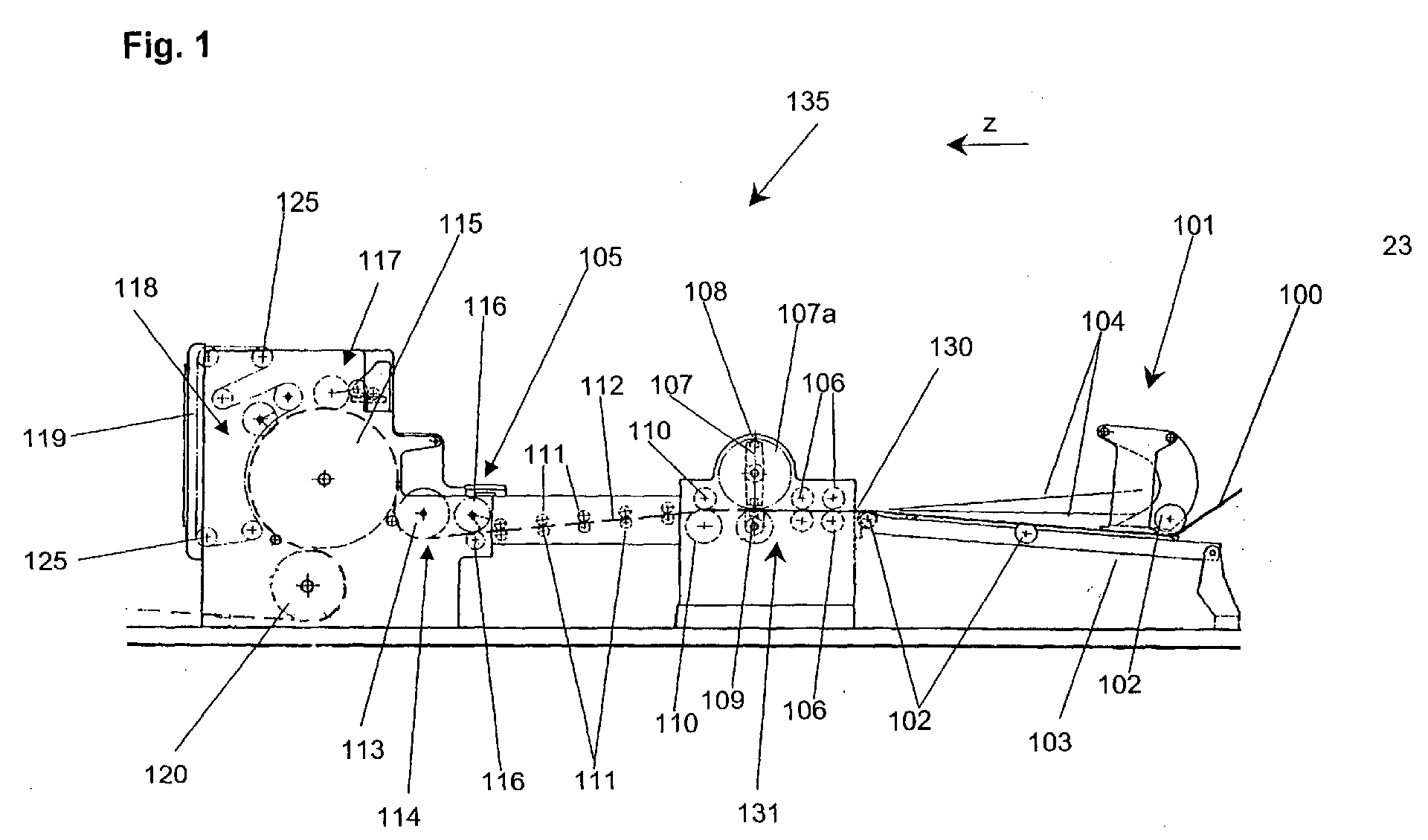
- FIG. 1 shows a sketched side view of a bag machine 135 Figure has been added to the technical background of show devices of the invention. This is primarily about the description of the core function of such a bag machine used in the Area of tubing section formation and grounding. For this purpose is at this point once again noted that the Bodenmacherzylinder and the Bodenöffner also in the German Auslegeschriften 1611699 as well 1080846 are explained.
- the bagging machine shown in FIG. 1 becomes a Paper web 100 from right to left in the transport direction of the paper web or the bag components z supplied.
- the Hose forming station 101 which includes the rollers 102, which also includes the Lead conveyor belt 103, the paper web to a tube 130th merged.
- This process is also symbolized by the lines 104, which represent the edges of the paper web when folded.
- the tear-off unit 131 To this Tear-off include initially the preferred rollers 106, which the paper web lead and the paper webs in opposition to each other Lock preferred rollers. After passing through the nips between the preferred rollers of the paper tube from the knife 108, which at the rotating blade carrier 107 is locked, which the knife along the dashed path 107a leads, perforated. Forms itself during the perforation process the counter-pressure cylinder 109 a counter-position. On the knife carrier 107 are two knives 108 attached so that upon one rotation of the knife carrier 107 two cross sections on the tube web 130 arise.
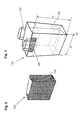
- Figure 2 shows once again a bag, as in such a Bag machine 135 can be made.
- This bag 123 has Gussets 122.
- FIG. 3 shows a somewhat more advanced bag 121 with carrying handles 124, which has been additionally fixed with a cover sheet 125 to the bag are.
- carrying handles and the method and apparatus for their preparation and the attachment to the bag are known in the art and are for example in DE 42 05 062 A1, which was already mentioned at the beginning, shown.
- carrying handle stations form part of the Bag machine, which are downstream of the Bodenmacherzylinder.
- the But carrying handle station can also already before the hose forming station Figur 6 also clarifies once again the design of the Bag. So the width and height of the bag is shown again. The Height of the bag is determined by the length of hose section, which of the Abr constitustation is defined determined.
- the height of the bag or the hose section length in the first Line through the diameter of the circumferential circle of the knife carrier 107th certainly.
- the width results from the width of the paper web and the Settings of the hose station 101. Even with width changes must extensive changes to the settings of the tools, for example on Bodenmacherzylinder, be made.
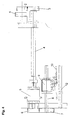
- FIG. 4 shows a section of the ground station 117 in a detailed view.
- the drive of the bottom folding station is effected by a shaft, not shown, which supplies a deflection gear 1 with a drive torque.
- the deflection gear is preceded by elliptical gears, which provide for differences in speed compared to the speed of the drive shaft.
- the shaft 4 which in turn ends in a differential gear 5.
- This differential gear 5 drives another gear 6.
- the gear 6 drives the shaft 8 via another gear 7. From the shaft 8 torque from the reversing gear 9 on the rotatable part, which is designed as a sheet 10, transmitted.
- This sheet 10 which may be sickle-shaped, is thereby set in rotation. Due to the temporarily higher rotational speeds during a revolution compared to the rotational speed of the drive shaft, the sheet 10 is able to fold down the bottom flap in the transport direction of the hose piece.
- the deflection gear 9 is fixed to a carrier 11. This carrier 11 is slidably mounted in the direction of the double arrow A in the direction of the rail 12. In this way, the closing mechanism, consisting of the deflection gear 9 and the sheet 10 can be adjusted to the width of the hose piece without having to replace the sheet.
Landscapes
- Making Paper Articles (AREA)
- Auxiliary Devices For And Details Of Packaging Control (AREA)
- Supplying Of Containers To The Packaging Station (AREA)
- Closing Of Containers (AREA)
Abstract
Die Erfindung beschreibt eine Beutelmaschine (135) zur Herstellung von Beuteln aus einer Schlauchbahn, welche über einen Bodenmacherzylinder verfügt. In dieser Beutelmaschine (135) ist zumindest ein Bodenschließmittel vorgesehen, das ein rotierbares Teil (10) umfasst, welches die in Transportrichtung (z) transportierten Beutelbodenbestandteile zeitweise mitnimmt und hierbei verschließt. Dabei ist der Angriffspunkt des rotierbaren Teils (10), an dem das rotierbare Teil in Abhängigkeit vom Bodenformat an die Teile des Beutelbodens, die zu schließen sind, angreift, einstellbar.The invention describes a bag machine (135) for the production of bags a tubular web, which has a Bodenmacherzylinder. In this Bag machine (135) is provided at least one bottom closing means, the one rotatable part (10), which transported in the transport direction (z) Occasionally entrains bag bottom components and closes them. It is the Point of attack of the rotatable part (10) on which the rotatable part in dependence from the bottom format to the parts of the bottom of the bag which are to be closed, adjustable.
Die Phasenlage des rotierbaren Teils (10) zum Bodenmacherzylinder (115) ist bei
Betrieb der Beutelmaschine (135) verstellbar.
Description
Die Erfindung betrifft einen Bodenmacherzylinder einer Beutelmaschine nach dem Oberbegriff des Anspruchs 1.The invention relates to a Bodenmacherzylinder a bag machine after the preamble of claim 1.
Beutelmaschinen sind bekannt. Sie werden beispielsweise in Schriften DE 42 05 062 A1, DE 197 02 144 A1 und F 2 548 161 gezeigt. In der Regel ist das funktionale Kernstück einer solchen Maschine ein Bodenmacherzylinder. Dieser Bodenmacherzylinder übernimmt in der Regel Schlauchstücke, welche aus einem Papierschlauch, der von einer Abwickeleinheit abgewickelt worden ist, in einer Abrisseinheit zu Papierschlauchstücken oder -abschnitten vereinzelt worden ist. Der Bodenmacherzylinder übernimmt diese Papierschlauchstücke, arretiert diese an seinem Umfang und führt sie während einer Umdrehung verschiedenen Bearbeitungsstationen, die um den Bodenmacherzylinder angeordnet sind, zu. Hierbei werden an den Schlauchstücken Einschläge ausgebildet, welche verleimt und zusammen gefaltet werden und auf diese Weise feste Beutelböden bilden. In der Regel wird das Schlauchstück mit dem späteren Boden voraus transportiert.Pouch machines are known. They are used, for example, in DE 42 05 062 A1, DE 197 02 144 A1 and F 2 548 161. In general, that is functional core of such a machine is a bottoming cylinder. This Bottom cylinder usually takes pieces of hose, which made a paper tube which has been unwound from an unwinding unit, in a tear unit to paper tube pieces or sections isolated has been. The Bodenmacherzylinder takes over these paper tube pieces, locks it to its circumference and guides it during a turn various processing stations that are around the floor maker cylinder are arranged, too. Here are the hose pieces impacts formed, which are glued and folded together and on this Form solid bag bottoms. In general, the hose piece with the transported later soil ahead.
Zur Schließung des Bodens ist eine der Bodenklappen, welche zur Bildung des Bodens übereinander gelegt werden müssen, zu ergreifen und zu falten. Eine der Bodenklappen kann dadurch geschlossen werden, dass diese Bodenklappe auf einen fest montierten Widerstand läuft und dadurch umgeklappt wird. Die zweite Bodenklappe muss jedoch in Transportrichtung umgeklappt werden. Dazu muss diese Bodenklappe kurzzeitig schneller bewegt werden als das Schlauchstück. Zu diesem Zweck befinden sich am Umfang des Bodenmacherzylinders rotierende Teile, die in der Regel sichelförmig ausgebildet sind. Diese werden vorzugsweise über Ellipsenräder angetrieben, welche mechanisch mit dem Antrieb des Bodenmacherzylinders gekoppelt sind. Mithilfe der Ellipsenräder werden die rotierenden Teile kurzzeitig in einer so hohen Geschwindigkeit bewegt, dass sie sich schneller als das Schlauchstück bewegen und so die Bodenklappe zu schließen vermögen. Dabei ist es aber auch wichtig, die Phasenlage, die die rotierenden Teile relativ zum Bodenmacherzylinder einnehmen, in Abhängigkeit von dem Bodenformat und damit in Abhängigkeit von der Größe der Bodenklappe einzustellen. Bei einem Formatwechsel ist es daher erforderlich, die rotierenden Teile von dem Antrieb zu lösen, gemäß dem neuen Format neu zu justieren und wieder zu befestigen. Zusätzlich müssen die rotierenden Teile gegen solchen größeren oder kleineren Ausmaßes ausgetauscht werden, wenn Schlauchstücke kleinerer beziehungsweise größere Breite zur Herstellung von Beuteln verwendet werden.To close the floor is one of the bottom flaps, which is used to form the Soil must be placed on top of each other, to grab and fold. A The bottom flaps can be closed by using this bottom flap on a fixed resistor runs and is folded over. The second bottom flap, however, must be folded in the transport direction. This bottom flap must be moved faster than that for a short time Piece of hose. For this purpose, the scope of the Treadmill rotating parts, usually sickle-shaped are formed. These are preferably driven by elliptical wheels, which are mechanically coupled to the drive of the Bodenmacherzylinders. Using the elliptical wheels, the rotating parts are briefly in such a way high speed moves faster than the hose piece move and thus be able to close the bottom flap. But that's it Also important, the phase position, the rotating parts relative to Take Bodenmacherzylinder, depending on the soil format and to adjust depending on the size of the bottom flap. At a Format change therefore requires the rotating parts from the drive to be readjusted and readjusted according to the new format. In addition, the rotating parts against such larger or smaller Extent are replaced when pieces of hose smaller or larger width used for the production of bags become.
Diese Anpassungen der rotierbaren Teile bei einem Formatwechsel ist jedoch sehr umständlich und zeitraubend.However, these adjustments of the rotatable parts in a format change is very cumbersome and time consuming.
Aufgabe der vorliegenden Erfindung ist es daher, eine Beutelmaschine vorzuschlagen, bei der die Anpassung der rotierenden Teile an neue Beutelformate einfacher und schneller erfolgen kann.Object of the present invention is therefore a bag machine to propose adapting the rotating parts to new ones Bag formats can be done easier and faster.
Die Aufgabe wird durch die Merkmale der kennzeichnenden Teile der
Ansprüche 1 und 4 gelöst.The task is characterized by the characteristics of the characterizing parts of the
Demzufolge ist die Phasenlage des rotierbaren Teils zum Bodenmacherzylinder bei Betrieb der Beutelmaschine verstellbar. Auf diese Weise wird vermieden, zum Zwecke des Formatwechsels die Beutelmaschine still zu setzen. Weiterhin muss das rotierbare Teil bei einem Formatwechsel nicht mehr ausgetauscht werden. Ein Formatwechsel kann damit bedeutend schneller erfolgen.As a result, the phase position of the rotatable part is the grounding cylinder adjustable during operation of the bag machine. This will avoid to put the bag machine down for the purpose of format change. Farther the rotatable part no longer needs to be replaced when the format is changed become. A format change can thus be done much faster.
Besonders vorteilhaft ist es, wenn die Bewegung des Bodenmacherzylinders und des rotierbaren Teils mechanisch gekoppelt sind und wenn in der Beutelmaschine zumindest ein Differential vorgesehen ist, mit welchem die Verstellung der Phasenlage vorgenommen wird. In einem solchen Differential kann der Teil, welcher die rotierbaren Teile antreiben, gegenüber dem Antrieb des Bodenmacherzylinders verdreht werden. Dieses kann beispielsweise mechanisch, aber auch mittels eines Stellmotors erfolgen.It is particularly advantageous if the movement of the Bodenmacherzylinders and the rotatable part are mechanically coupled and when in the Bag machine at least one differential is provided with which the Adjustment of the phase position is made. In such a differential For example, the part which drives the rotatable parts can be opposite to the drive twisted the Bodenmacherzylinders. This can for example mechanically, but also by means of a servomotor.
In einer weiteren Ausführungsform der Erfindung sind für den Bodenmacherzylinder und das rotierbares Teil unterschiedliche Antriebe vorgesehen. Dabei kann die Verstellung der Phasenlage zwischen dem Bodenmacherzylinder und dem rotierbaren Teil über ein unterschiedliche Ansteuerung der Antriebe vornehmbar sein. In dieser Ausführungsform wird die Verwendung von getrieblichen Mitteln vermieden, wodurch die Verschleißanfälligkeit der Beutelmaschine erheblich reduziert wird.In a further embodiment of the invention are for the Bodenmacher cylinder and the rotatable part different drives intended. In this case, the adjustment of the phase angle between the Bodenmacherzylinder and the rotatable part on a different Control of the drives be vornehmbar. In this embodiment, the Using geared means avoided, causing the Susceptibility to wear of the bag machine is significantly reduced.
Weitere Details und Ausführungsbeispiele der vorliegenden Erfindung werden in der gegenständlichen Beschreibung und der Zeichnung offenbart.Further details and embodiments of the present invention will become in the subject description and the drawing.
Die einzelnen Figuren zeigen:
- Fig. 1
- Skizzierte Seitenansicht einer Beutelmaschine.
- Fig. 2
- Skizzierte Ansicht eines auf einer solchen Maschine hergestellten Beutels.
- Fig. 3
- Ein solcher Beutel, der zusätzlich mit Handgriffen beaufschlagt ist.
- Fig. 4
- die Vorderansicht der Vorrichtung zur Bodenschließung
- Fig. 1
- Sketched side view of a bag machine.
- Fig. 2
- Sketched view of a bag made on such a machine.
- Fig. 3
- Such a bag, which is additionally acted upon by handles.
- Fig. 4
- the front view of the device for bottom closure
Figur 1 zeigt eine skizzierte Seitenansicht einer Beutelmaschine 135. Diese
Figur wurde eingefügt, um den technischen Hintergrund der
erfindungsgemäßen Vorrichtungen zu zeigen. Hierbei geht es in erster Linie um
die Beschreibung der Kernfunktion einer solchen Beutelmaschine, die im
Bereich der Schlauchabschnittbildung und Bodenmachung besteht. Hierzu wird
an dieser Stelle noch einmal angemerkt, dass der Bodenmacherzylinder und
der Bodenöffner auch in den deutschen Auslegeschriften 1611699 sowie
1080846 erklärt sind. Der in Figur 1 gezeigten Beutelmaschine wird eine
Papierbahn 100 von rechts nach links in der Transportrichtung der Papierbahn
beziehungsweise der Beutelbestandteile z zugeführt. In der
Schlauchbildungsstation 101, welche die Walzen 102 umfasst, die auch das
Transportband 103 führen, wird die Papierbahn zu einem Schlauch 130
zusammengelegt. Dieser Vorgang wird auch durch die Striche 104 symbolisiert,
welche die Ränder der Papierbahn bei ihrem Zusammenlegen darstellen. Der
fertige Papierschlauch 130 wird dem Abreißwerk 131 zugeführt. Zu diesem
Abreißwerk gehören zunächst die Vorzugswalzen 106, welche die Papierbahn
führen und die Papierbahnen zwischen gegeneinander in Opposition stehenden
Vorzugswalzen arretieren. Nach dem Durchlaufen der Walzenspalte zwischen
den Vorzugswalzen wird der Papierschlauch von dem Messer 108, welches an
dem rotierenden Messerträger 107 arretiert ist, welcher das Messer entlang der
gestrichelten Bahn 107a führt, perforiert. Beim Perforationsvorgang selbst bildet
der Gegendruckzylinder 109 eine Gegenlage. An dem Messerträger 107 sind
zwei Messer 108 angebracht, so dass bei einer Umdrehung des Messerträgers
107 zwei Querschnitte auf der Schlauchbahn 130 entstehen. Der
Gegendruckzylinder 109 vollführt während dieser Zeit zwei Umdrehungen. Der
vorperforierte Schlauch kommt sodann in den Walzenspalt zwischen den
beiden Abreißzylindern 110, welche schneller laufen als die Vorzugswalzen
106. Dadurch wird der Schlauch an der Perforationsstelle abgerissen, was
zwischen dem Messer 108 und dem Walzenspalt zwischen den Abreißzylindern
110 erfolgt. Es bleibt anzumerken, dass der Papierschlauch jetzt zu
Papierschlauchabschnitten 112 vereinzelt ist. Diese Papierschlauchabschnitte
112 werden zunächst von den Transportwalzen 111 weiter transportiert. Sie
erreichen die Längseinschnittstation 105, bei der zwischen den beiden Walzen
116 ein Längsschnitt in das vordere Ende des Schlauchabschnitts eingebracht
wird, was zur anschließenden Bodenbildung notwendig ist. Nach der
Längseinschnittstation 105 werden die Schlauchabschnitte der
Bodenöffnungsstation 114, welche hauptsächlich aus dem Bodenöffner 113
besteht, zugeführt. Hier werden die Böden geöffnet. Wie bereits erwähnt zeigt
die vorgenannte deutsche Auslegeschrift 1611609 einen solchen Bodenöffner.
Schließlich werden die Schlauchstücke dem Bodenmacherzylinder 115
zugeführt, der diese übernimmt und an verschiedenen Bearbeitungsstationen,
welche um den Bodenmacherzylinder angeordnet sind, vorbeiführt. Die erste
dieser Stationen ist die Bodenfaltungs- und -Beleimungsstation 117. Die
einzelnen Elemente dieser Station sind nur skizziert dargestellt und können den
zitierten Druckschriften entnommen werden. In jedem Fall sind sie dem
Fachmann bekannt. Nach Durchlaufen der Bodenfaltungs- und -
beleimungsstation werden die Böden in der Bodenschließungsstation fixiert
beziehungsweise angepresst. Dieses geschieht hauptsächlich dadurch, dass
die Schlauchabschnitte beziehungsweise Beutel zwischen dem
Bodenmacherzylinder 115 und einem Pressband 119, welches von den Walzen
125 geführt wird, verpresst werden. Bei der gezeigten Beutelmaschine laufen
die Schlauchabschnitte beziehungsweise Beutel 112 dann um einen
Umkehrzylinder 120, welcher dafür sorgt, dass sich die Beutel beziehungsweise
Schlauchabschnitte weiter von rechts nach links in der Transportrichtung der
Beutelbestandteile z bewegen. In der Regel werden die mit fertig gelegten und
fixierten Böden versehenen Schlauchabschnitte dann weiteren
Bearbeitungsstationen zugeführt. So werden die Beutel oft bedruckt und/oder
mit Tragegriffen versehen. An dieser Stelle wird jedoch auf die Darstellung
solcher Arbeitsstationen verzichtet. Es wurde ebenfalls darauf verzichtet, die
Abwicklungen für die Papierbahn 100, welche der Schlauchbildungsstation 101
vorgelagert sind, zu zeigen.FIG. 1 shows a sketched side view of a
Figur 2 zeigt jedoch noch einmal einen Beutel, wie er in einer solchen
Beutelmaschine 135 hergestellt werden kann. Dieser Beutel 123 besitzt
Seitenfalten 122.However, Figure 2 shows once again a bag, as in such a
Die Figur 3 zeigt einen etwas fortgeschritteneren Beutel 121 mit Tragegriffen
124, welche zusätzlich mit einem Deckblatt 125 an dem Beutel fixiert worden
sind. Auch Tragegriffe und die Verfahren und Vorrichtung zu deren Herstellung
und der Anbringung am Beutel sind dem Fachmann bekannt und werden
beispielsweise in der DE 42 05 062 A1, welche eingangs schon erwähnt wurde,
gezeigt. In der Regel bilden solche Tragegriffstationen Bestandteile der
Beutelmaschine, welche dem Bodenmacherzylinder nachgelagert sind. Die
Traggriffstation kann jedoch auch bereits vor der Schlauchbildungsstation
angeordnet sein Figur 6 verdeutlicht auch noch einmal die Gestaltung des
Beutels. So ist die Breite und Höhe des Beutels noch einmal dargestellt. Die
Höhe des Beutels wird durch die Schlauchabschnittlänge, welche von der
Abreißstation definiert wird, bestimmt. Bei der gezeigten Beutelmaschine wird
die Höhe des Sackes beziehungsweise die Schlauchabschnittslänge in erster
Linie durch den Durchmesser des Umfangkreises des Messerträgers 107
bestimmt. Die Breite ergibt sich aus der Breite der Papierbahn und den
Einstellungen der Schlauchlegestation 101. Auch bei Breitenwechseln müssen
umfangreiche Änderungen der Einstellungen der Werkzeuge, beispielsweise
am Bodenmacherzylinder, vorgenommen werden.FIG. 3 shows a somewhat more
Die Figur 4 zeigt einen Ausschnitt der der Bodenstation 117 in einer
Detailansicht. Der Antrieb der Bodenfaltungsstation erfolgt durch eine nicht
dargestellte Welle, welche ein Umlenkgetriebe 1 mit einem
Antriebsdrehmoment versorgt. Dem Umlenkgetriebe vorgelagert sind
Ellipsenzahnräder, welche für Geschwindigkeitsdifferenzen im Vergleich zur
Geschwindigkeit der Antriebswelle sorgen. Über zwei Zahnräder 2, 3 wird das
Drehmoment auf die Welle 4 übertragen, welche wiederum in einem
Differentialgetriebe 5 endet. Dieses Differentialgetriebe 5 treibt ein weiteres
Zahnrad 6 an. Mithilfe des Differentialgetriebes 5 kann eine
Phasenverschiebung zwischen der Welle 4 und dem Zahnrad 6 erreicht
werden. Das Zahnrad 6 treibt über ein weiteres Zahnrad 7 die Welle 8 an. Von
der Welle 8 wird Drehmoment von dem Umlenkgetriebe 9 auf das rotierbare
Teil, welches als Blech 10 ausgeführt ist, übertragen. Dieses Blech 10, welches
sichelförmig ausgebildet sein kann, wird dadurch in Rotation versetzt. Aufgrund
der zeitweise höheren Rotationsgeschwindigkeiten während eines Umlaufs im
Vergleich zur Rotationsgeschwindigkeit der Antriebswelle ist das Blech 10 in
der Lage, die Bodenklappe in Transportrichtung des Schlauchstücks
umzuklappen. Das Umlenkgetriebe 9 ist an einem Träger 11 befestigt. Dieser
Träger 11 ist in Richtung des Doppelpfeiles A in Richtung der Schiene 12
verschieblich gelagert. Auf diese Weise kann der Schließmechanismuss,
bestehend aus dem Umlenkgetriebe 9 und dem Blech 10 auf die Breite des
Schlauchstückes eingestellt werden, ohne das Blech austauschen zu müssen.
Claims (4)
die Phasenlage des rotierbaren Teils (10) zum Bodenmacherzylinder (115) bei Betrieb der Beutelmaschine (135) verstellbar ist.Bag machine (135) for making bags from a tubular web,
the phase position of the rotatable part (10) is adjustable to the bottoming cylinder (115) during operation of the bag machine (135).
dadurch gekennzeichnet, dass
das die Bewegungen des Bodenmacherzylinders (115) und des rotierbaren Teils (10) mechanisch gekoppelt sind und dass in der Beutelmaschine (135) zumindest ein Differential (5) vorgesehen ist, mit welchem Verstellung der Phasenlage vorgenommen werden kann.Bag machine (135) according to claim 1
characterized in that
in that the movements of the bottom maker cylinder (115) and of the rotatable part (10) are mechanically coupled and in that at least one differential (5) is provided in the bag machine (135) with which adjustment of the phase position can be performed.
dadurch gekennzeichnet, dass
der Bodemacherzylinder (115) und das rotierbare Teil (10) über unterschiedliche Antriebe verfügen und dass die Verstellung der Phasenlage über eine unterschiedliche Ansteuerung der Antriebe vornehmbar ist.Bag machine (135) according to claim 1
characterized in that
the Bodemacher cylinder (115) and the rotatable part (10) have different drives and that the adjustment of the phase position via a different control of the drives is vornehmbar.
dadurch gekennzeichnet, dass
das rotierbare Teil quer zur Transportrichtung (z) der Beutelbodenbestandteile verschiebbar sind.Bag machine according to the preamble of claim 1
characterized in that
the rotatable part is displaceable transversely to the transport direction (z) of the bag base components.
Applications Claiming Priority (2)
| Application Number | Priority Date | Filing Date | Title |
|---|---|---|---|
| DE10349223 | 2003-10-20 | ||
| DE10349223 | 2003-10-20 |
Publications (3)
| Publication Number | Publication Date |
|---|---|
| EP1525976A2 true EP1525976A2 (en) | 2005-04-27 |
| EP1525976A3 EP1525976A3 (en) | 2006-09-13 |
| EP1525976B1 EP1525976B1 (en) | 2009-11-25 |
Family
ID=34384406
Family Applications (1)
| Application Number | Title | Priority Date | Filing Date |
|---|---|---|---|
| EP04022402A Expired - Lifetime EP1525976B1 (en) | 2003-10-20 | 2004-09-21 | Bottom closing device in a bag making machine |
Country Status (3)
| Country | Link |
|---|---|
| EP (1) | EP1525976B1 (en) |
| AT (1) | ATE449681T1 (en) |
| DE (1) | DE502004010414D1 (en) |
Cited By (3)
| Publication number | Priority date | Publication date | Assignee | Title |
|---|---|---|---|---|
| CN104602901A (en) * | 2012-04-30 | 2015-05-06 | 罗伯托·埃米利奥·金加尔迪 | machines for making bag bottoms |
| EP2864114B1 (en) | 2012-06-20 | 2016-06-22 | Holweg Group | Machine for manufacturing flat bottom bags |
| CN108189482A (en) * | 2017-12-29 | 2018-06-22 | 山东新华医疗器械股份有限公司 | A kind of blood bag Bag Making Machine and its rotation tube feeding device |
Family Cites Families (5)
| Publication number | Priority date | Publication date | Assignee | Title |
|---|---|---|---|---|
| DE806312C (en) * | 1949-06-29 | 1951-06-14 | Windmoeller & Hoelscher | Machine for the production of cross-bottom bags |
| DE1278211B (en) * | 1963-02-02 | 1968-09-19 | Windmoeller & Hoelscher | Device in bag machines working in the longitudinal conveying process for folding over the trailing bottom side cover of both cross and block bottom bags |
| DE1611699C2 (en) * | 1967-08-25 | 1975-11-20 | Windmoeller & Hoelscher, 4540 Lengerich | Device for producing the bottoms in a block bottom bag machine |
| DE1611705A1 (en) * | 1967-11-03 | 1971-01-14 | Windmoeller & Hoelscher | Device for folding down the trailing bottom flap of cross and block bottom bags on bag machines working in the longitudinal conveying process |
| DE1910733B2 (en) * | 1969-03-03 | 1971-07-29 | Spiess, Helmut, Dr Ing , 8906 Gerst hofen | SHEET FEEDER DRIVEN BY A SHEET PROCESSING MACHINE |
-
2004
- 2004-09-21 DE DE502004010414T patent/DE502004010414D1/en not_active Expired - Lifetime
- 2004-09-21 EP EP04022402A patent/EP1525976B1/en not_active Expired - Lifetime
- 2004-09-21 AT AT04022402T patent/ATE449681T1/en active
Cited By (5)
| Publication number | Priority date | Publication date | Assignee | Title |
|---|---|---|---|---|
| CN104602901A (en) * | 2012-04-30 | 2015-05-06 | 罗伯托·埃米利奥·金加尔迪 | machines for making bag bottoms |
| EP2864114B1 (en) | 2012-06-20 | 2016-06-22 | Holweg Group | Machine for manufacturing flat bottom bags |
| US10703065B2 (en) | 2012-06-20 | 2020-07-07 | Holweg Group | Machine for manufacturing flat bottom bags |
| CN108189482A (en) * | 2017-12-29 | 2018-06-22 | 山东新华医疗器械股份有限公司 | A kind of blood bag Bag Making Machine and its rotation tube feeding device |
| CN108189482B (en) * | 2017-12-29 | 2023-05-16 | 山东新华医疗器械股份有限公司 | A blood bag bag making machine and its rotating tube loading device |
Also Published As
| Publication number | Publication date |
|---|---|
| EP1525976B1 (en) | 2009-11-25 |
| DE502004010414D1 (en) | 2010-01-07 |
| EP1525976A3 (en) | 2006-09-13 |
| ATE449681T1 (en) | 2009-12-15 |
Similar Documents
| Publication | Publication Date | Title |
|---|---|---|
| EP0481172B1 (en) | Rotary printing machine for book and calendar printing, with two longitudinal folding devices | |
| EP0977668B1 (en) | Device for adjusting folding jaws | |
| DE602004012202T2 (en) | Method and device for the overlapping of sheets | |
| DE3113616C2 (en) | Device for folding cardboard blanks into box tubes | |
| EP1074500B1 (en) | Printed products transport cylinder of a folding apparatus | |
| DE19716628C2 (en) | Method and device for cross-folding signatures | |
| DE102008017726A1 (en) | Apparatus and method for making bags | |
| EP0659670A1 (en) | Flying tuck folding device for a rotary printing press | |
| CH657834A5 (en) | VARIABLE FOLDING APPARATUS WITH A CUTTING CYLINDER COUPLING AND A PAIRING ROLLER COUPLING BELOW THIS. | |
| EP1116560A2 (en) | Cutting device with adjustable cutting lenght | |
| EP0639453B1 (en) | Cross-perforating device | |
| EP0661227A1 (en) | Flying tuck folding device | |
| DE4137818A1 (en) | Adjustment of strip tension in roller rotation printing machine - involves draw rollers fitted to fold funnel driven by speed-adjustable drive | |
| EP1525976B1 (en) | Bottom closing device in a bag making machine | |
| EP0760274A1 (en) | Means for adjusting perforating devices | |
| DE19932070A1 (en) | Guide for printed copies in rotary printer folder consists of conveyor material, discharge gap between cylinders, guide body swiveling on axle and container | |
| EP2319788B1 (en) | Folding machine with a pressing device | |
| DE1280030B (en) | Machine for making bags from pre-printed webs | |
| EP2017088B1 (en) | Stapler | |
| EP1516719B1 (en) | Bottom forming cylinder of a bag making machine | |
| DE540372C (en) | Machine for the production of window envelopes | |
| DE19805320B4 (en) | Device for laying a film web in Z-shaped folds | |
| DE10101849C1 (en) | Folder with a book perforator | |
| DE10261257A1 (en) | Paper or plastics bag manufacturing machine works on flattened hose and has rollers for perforating paper or plastics foil and for folding it to shape and for cutting off ends | |
| CH239019A (en) | Folder for variable sheet lengths. |
Legal Events
| Date | Code | Title | Description |
|---|---|---|---|
| PUAI | Public reference made under article 153(3) epc to a published international application that has entered the european phase |
Free format text: ORIGINAL CODE: 0009012 |
|
| AK | Designated contracting states |
Kind code of ref document: A2 Designated state(s): AT BE BG CH CY CZ DE DK EE ES FI FR GB GR HU IE IT LI LU MC NL PL PT RO SE SI SK TR |
|
| AX | Request for extension of the european patent |
Extension state: AL HR LT LV MK |
|
| PUAL | Search report despatched |
Free format text: ORIGINAL CODE: 0009013 |
|
| AK | Designated contracting states |
Kind code of ref document: A3 Designated state(s): AT BE BG CH CY CZ DE DK EE ES FI FR GB GR HU IE IT LI LU MC NL PL PT RO SE SI SK TR |
|
| AX | Request for extension of the european patent |
Extension state: AL HR LT LV MK |
|
| 17P | Request for examination filed |
Effective date: 20070313 |
|
| AKX | Designation fees paid |
Designated state(s): AT BE BG CH CY CZ DE DK EE ES FI FR GB GR HU IE IT LI LU MC NL PL PT RO SE SI SK TR |
|
| 17Q | First examination report despatched |
Effective date: 20070913 |
|
| GRAP | Despatch of communication of intention to grant a patent |
Free format text: ORIGINAL CODE: EPIDOSNIGR1 |
|
| GRAS | Grant fee paid |
Free format text: ORIGINAL CODE: EPIDOSNIGR3 |
|
| GRAA | (expected) grant |
Free format text: ORIGINAL CODE: 0009210 |
|
| AK | Designated contracting states |
Kind code of ref document: B1 Designated state(s): AT BE BG CH CY CZ DE DK EE ES FI FR GB GR HU IE IT LI LU MC NL PL PT RO SE SI SK TR |
|
| REG | Reference to a national code |
Ref country code: GB Ref legal event code: FG4D Free format text: NOT ENGLISH |
|
| REG | Reference to a national code |
Ref country code: CH Ref legal event code: EP |
|
| REG | Reference to a national code |
Ref country code: IE Ref legal event code: FG4D |
|
| REF | Corresponds to: |
Ref document number: 502004010414 Country of ref document: DE Date of ref document: 20100107 Kind code of ref document: P |
|
| REG | Reference to a national code |
Ref country code: NL Ref legal event code: VDEP Effective date: 20091125 |
|
| PG25 | Lapsed in a contracting state [announced via postgrant information from national office to epo] |
Ref country code: PT Free format text: LAPSE BECAUSE OF FAILURE TO SUBMIT A TRANSLATION OF THE DESCRIPTION OR TO PAY THE FEE WITHIN THE PRESCRIBED TIME-LIMIT Effective date: 20100325 Ref country code: FI Free format text: LAPSE BECAUSE OF FAILURE TO SUBMIT A TRANSLATION OF THE DESCRIPTION OR TO PAY THE FEE WITHIN THE PRESCRIBED TIME-LIMIT Effective date: 20091125 Ref country code: SE Free format text: LAPSE BECAUSE OF FAILURE TO SUBMIT A TRANSLATION OF THE DESCRIPTION OR TO PAY THE FEE WITHIN THE PRESCRIBED TIME-LIMIT Effective date: 20091125 |
|
| PG25 | Lapsed in a contracting state [announced via postgrant information from national office to epo] |
Ref country code: PL Free format text: LAPSE BECAUSE OF FAILURE TO SUBMIT A TRANSLATION OF THE DESCRIPTION OR TO PAY THE FEE WITHIN THE PRESCRIBED TIME-LIMIT Effective date: 20091125 Ref country code: CY Free format text: LAPSE BECAUSE OF FAILURE TO SUBMIT A TRANSLATION OF THE DESCRIPTION OR TO PAY THE FEE WITHIN THE PRESCRIBED TIME-LIMIT Effective date: 20091125 Ref country code: SI Free format text: LAPSE BECAUSE OF FAILURE TO SUBMIT A TRANSLATION OF THE DESCRIPTION OR TO PAY THE FEE WITHIN THE PRESCRIBED TIME-LIMIT Effective date: 20091125 |
|
| PG25 | Lapsed in a contracting state [announced via postgrant information from national office to epo] |
Ref country code: RO Free format text: LAPSE BECAUSE OF FAILURE TO SUBMIT A TRANSLATION OF THE DESCRIPTION OR TO PAY THE FEE WITHIN THE PRESCRIBED TIME-LIMIT Effective date: 20091125 Ref country code: ES Free format text: LAPSE BECAUSE OF FAILURE TO SUBMIT A TRANSLATION OF THE DESCRIPTION OR TO PAY THE FEE WITHIN THE PRESCRIBED TIME-LIMIT Effective date: 20100308 Ref country code: EE Free format text: LAPSE BECAUSE OF FAILURE TO SUBMIT A TRANSLATION OF THE DESCRIPTION OR TO PAY THE FEE WITHIN THE PRESCRIBED TIME-LIMIT Effective date: 20091125 Ref country code: DK Free format text: LAPSE BECAUSE OF FAILURE TO SUBMIT A TRANSLATION OF THE DESCRIPTION OR TO PAY THE FEE WITHIN THE PRESCRIBED TIME-LIMIT Effective date: 20091125 Ref country code: BG Free format text: LAPSE BECAUSE OF FAILURE TO SUBMIT A TRANSLATION OF THE DESCRIPTION OR TO PAY THE FEE WITHIN THE PRESCRIBED TIME-LIMIT Effective date: 20100225 Ref country code: NL Free format text: LAPSE BECAUSE OF FAILURE TO SUBMIT A TRANSLATION OF THE DESCRIPTION OR TO PAY THE FEE WITHIN THE PRESCRIBED TIME-LIMIT Effective date: 20091125 |
|
| PG25 | Lapsed in a contracting state [announced via postgrant information from national office to epo] |
Ref country code: SK Free format text: LAPSE BECAUSE OF FAILURE TO SUBMIT A TRANSLATION OF THE DESCRIPTION OR TO PAY THE FEE WITHIN THE PRESCRIBED TIME-LIMIT Effective date: 20091125 Ref country code: CZ Free format text: LAPSE BECAUSE OF FAILURE TO SUBMIT A TRANSLATION OF THE DESCRIPTION OR TO PAY THE FEE WITHIN THE PRESCRIBED TIME-LIMIT Effective date: 20091125 |
|
| PLBE | No opposition filed within time limit |
Free format text: ORIGINAL CODE: 0009261 |
|
| STAA | Information on the status of an ep patent application or granted ep patent |
Free format text: STATUS: NO OPPOSITION FILED WITHIN TIME LIMIT |
|
| PG25 | Lapsed in a contracting state [announced via postgrant information from national office to epo] |
Ref country code: GR Free format text: LAPSE BECAUSE OF FAILURE TO SUBMIT A TRANSLATION OF THE DESCRIPTION OR TO PAY THE FEE WITHIN THE PRESCRIBED TIME-LIMIT Effective date: 20100226 |
|
| 26N | No opposition filed |
Effective date: 20100826 |
|
| BERE | Be: lapsed |
Owner name: WINDMOLLER & HOLSCHER K.G. Effective date: 20100930 |
|
| PG25 | Lapsed in a contracting state [announced via postgrant information from national office to epo] |
Ref country code: MC Free format text: LAPSE BECAUSE OF NON-PAYMENT OF DUE FEES Effective date: 20100930 |
|
| REG | Reference to a national code |
Ref country code: CH Ref legal event code: PL |
|
| REG | Reference to a national code |
Ref country code: FR Ref legal event code: ST Effective date: 20110531 |
|
| PG25 | Lapsed in a contracting state [announced via postgrant information from national office to epo] |
Ref country code: BE Free format text: LAPSE BECAUSE OF NON-PAYMENT OF DUE FEES Effective date: 20100930 Ref country code: FR Free format text: LAPSE BECAUSE OF NON-PAYMENT OF DUE FEES Effective date: 20100930 Ref country code: LI Free format text: LAPSE BECAUSE OF NON-PAYMENT OF DUE FEES Effective date: 20100930 Ref country code: CH Free format text: LAPSE BECAUSE OF NON-PAYMENT OF DUE FEES Effective date: 20100930 |
|
| PGFP | Annual fee paid to national office [announced via postgrant information from national office to epo] |
Ref country code: IE Payment date: 20110912 Year of fee payment: 8 |
|
| PGFP | Annual fee paid to national office [announced via postgrant information from national office to epo] |
Ref country code: AT Payment date: 20110826 Year of fee payment: 8 |
|
| PG25 | Lapsed in a contracting state [announced via postgrant information from national office to epo] |
Ref country code: LU Free format text: LAPSE BECAUSE OF NON-PAYMENT OF DUE FEES Effective date: 20100921 Ref country code: HU Free format text: LAPSE BECAUSE OF FAILURE TO SUBMIT A TRANSLATION OF THE DESCRIPTION OR TO PAY THE FEE WITHIN THE PRESCRIBED TIME-LIMIT Effective date: 20100526 |
|
| PG25 | Lapsed in a contracting state [announced via postgrant information from national office to epo] |
Ref country code: TR Free format text: LAPSE BECAUSE OF FAILURE TO SUBMIT A TRANSLATION OF THE DESCRIPTION OR TO PAY THE FEE WITHIN THE PRESCRIBED TIME-LIMIT Effective date: 20091125 |
|
| REG | Reference to a national code |
Ref country code: AT Ref legal event code: MM01 Ref document number: 449681 Country of ref document: AT Kind code of ref document: T Effective date: 20120921 |
|
| REG | Reference to a national code |
Ref country code: IE Ref legal event code: MM4A |
|
| PG25 | Lapsed in a contracting state [announced via postgrant information from national office to epo] |
Ref country code: AT Free format text: LAPSE BECAUSE OF NON-PAYMENT OF DUE FEES Effective date: 20120921 Ref country code: IE Free format text: LAPSE BECAUSE OF NON-PAYMENT OF DUE FEES Effective date: 20120921 |
|
| REG | Reference to a national code |
Ref country code: DE Ref legal event code: R079 Ref document number: 502004010414 Country of ref document: DE Free format text: PREVIOUS MAIN CLASS: B31B0029000000 Ipc: B31B0070000000 |
|
| PGFP | Annual fee paid to national office [announced via postgrant information from national office to epo] |
Ref country code: GB Payment date: 20180928 Year of fee payment: 15 |
|
| PGFP | Annual fee paid to national office [announced via postgrant information from national office to epo] |
Ref country code: DE Payment date: 20180930 Year of fee payment: 15 |
|
| PGFP | Annual fee paid to national office [announced via postgrant information from national office to epo] |
Ref country code: IT Payment date: 20180927 Year of fee payment: 15 |
|
| REG | Reference to a national code |
Ref country code: DE Ref legal event code: R119 Ref document number: 502004010414 Country of ref document: DE |
|
| PG25 | Lapsed in a contracting state [announced via postgrant information from national office to epo] |
Ref country code: DE Free format text: LAPSE BECAUSE OF NON-PAYMENT OF DUE FEES Effective date: 20200401 |
|
| PG25 | Lapsed in a contracting state [announced via postgrant information from national office to epo] |
Ref country code: IT Free format text: LAPSE BECAUSE OF NON-PAYMENT OF DUE FEES Effective date: 20190921 |
|
| GBPC | Gb: european patent ceased through non-payment of renewal fee |
Effective date: 20190921 |
|
| PG25 | Lapsed in a contracting state [announced via postgrant information from national office to epo] |
Ref country code: GB Free format text: LAPSE BECAUSE OF NON-PAYMENT OF DUE FEES Effective date: 20190921 |