EP1516719B1 - Bottom forming cylinder of a bag making machine - Google Patents
Bottom forming cylinder of a bag making machine Download PDFInfo
- Publication number
- EP1516719B1 EP1516719B1 EP04021275A EP04021275A EP1516719B1 EP 1516719 B1 EP1516719 B1 EP 1516719B1 EP 04021275 A EP04021275 A EP 04021275A EP 04021275 A EP04021275 A EP 04021275A EP 1516719 B1 EP1516719 B1 EP 1516719B1
- Authority
- EP
- European Patent Office
- Prior art keywords
- cylinder
- vacuum
- forming cylinder
- paper tube
- axial direction
- Prior art date
- Legal status (The legal status is an assumption and is not a legal conclusion. Google has not performed a legal analysis and makes no representation as to the accuracy of the status listed.)
- Expired - Lifetime
Links
- 238000000034 method Methods 0.000 claims description 4
- 238000006073 displacement reaction Methods 0.000 claims description 2
- 239000002689 soil Substances 0.000 description 5
- 230000032258 transport Effects 0.000 description 5
- 238000004026 adhesive bonding Methods 0.000 description 3
- 230000015572 biosynthetic process Effects 0.000 description 2
- 238000006243 chemical reaction Methods 0.000 description 2
- 238000003491 array Methods 0.000 description 1
- 230000000903 blocking effect Effects 0.000 description 1
- 238000011161 development Methods 0.000 description 1
- 230000018109 developmental process Effects 0.000 description 1
- 238000009434 installation Methods 0.000 description 1
- 239000007787 solid Substances 0.000 description 1
- 238000003971 tillage Methods 0.000 description 1
- 238000011144 upstream manufacturing Methods 0.000 description 1
Images


Classifications
-
- B—PERFORMING OPERATIONS; TRANSPORTING
- B31—MAKING ARTICLES OF PAPER, CARDBOARD OR MATERIAL WORKED IN A MANNER ANALOGOUS TO PAPER; WORKING PAPER, CARDBOARD OR MATERIAL WORKED IN A MANNER ANALOGOUS TO PAPER
- B31B—MAKING CONTAINERS OF PAPER, CARDBOARD OR MATERIAL WORKED IN A MANNER ANALOGOUS TO PAPER
- B31B70/00—Making flexible containers, e.g. envelopes or bags
- B31B70/02—Feeding or positioning sheets, blanks or webs
- B31B70/022—Holders for feeding or positioning sheets or webs
- B31B70/024—Rotating holders, e.g. star wheels, drums
-
- B—PERFORMING OPERATIONS; TRANSPORTING
- B31—MAKING ARTICLES OF PAPER, CARDBOARD OR MATERIAL WORKED IN A MANNER ANALOGOUS TO PAPER; WORKING PAPER, CARDBOARD OR MATERIAL WORKED IN A MANNER ANALOGOUS TO PAPER
- B31B—MAKING CONTAINERS OF PAPER, CARDBOARD OR MATERIAL WORKED IN A MANNER ANALOGOUS TO PAPER
- B31B2150/00—Flexible containers made from sheets or blanks, e.g. from flattened tubes
- B31B2150/001—Flexible containers made from sheets or blanks, e.g. from flattened tubes with square or cross bottom
- B31B2150/0012—Flexible containers made from sheets or blanks, e.g. from flattened tubes with square or cross bottom having their openings facing in the direction of movement
-
- B—PERFORMING OPERATIONS; TRANSPORTING
- B31—MAKING ARTICLES OF PAPER, CARDBOARD OR MATERIAL WORKED IN A MANNER ANALOGOUS TO PAPER; WORKING PAPER, CARDBOARD OR MATERIAL WORKED IN A MANNER ANALOGOUS TO PAPER
- B31B—MAKING CONTAINERS OF PAPER, CARDBOARD OR MATERIAL WORKED IN A MANNER ANALOGOUS TO PAPER
- B31B2160/00—Shape of flexible containers
- B31B2160/10—Shape of flexible containers rectangular and flat, i.e. without structural provision for thickness of contents
-
- B—PERFORMING OPERATIONS; TRANSPORTING
- B31—MAKING ARTICLES OF PAPER, CARDBOARD OR MATERIAL WORKED IN A MANNER ANALOGOUS TO PAPER; WORKING PAPER, CARDBOARD OR MATERIAL WORKED IN A MANNER ANALOGOUS TO PAPER
- B31B—MAKING CONTAINERS OF PAPER, CARDBOARD OR MATERIAL WORKED IN A MANNER ANALOGOUS TO PAPER
- B31B2160/00—Shape of flexible containers
- B31B2160/20—Shape of flexible containers with structural provision for thickness of contents
Definitions
- the invention relates to a bottoming cylinder of a bagging machine according to the preamble of claim 1.
- Pouch machines are known. They are for example in fonts DE 42 05 062 A1 . DE 197 02 144 A1 and F 2 548 161 shown.
- the functional core of such a machine is a floor maker cylinder.
- This Bodenmacherzylinder usually takes over pieces of tubing, which has been separated from a paper tube, which has been unwound from a unwinding unit in a tear unit to paper tube pieces or sections.
- the Bodenmacherzylinder takes over these paper tube pieces, arresting them at its periphery and leads them during one revolution to various processing stations, which are arranged around the Bodenmacherzylinder to. In this case, sleeves are formed on the tube pieces, which are glued and thus form solid bag bottoms.
- Both grippers and vacuum suction devices are used to lock the hose sections to the floor maker cylinder. It has proven useful to use both devices together on more modern bagging machines. On bag machines often all possible format changes are made. The possible format changes include a change in the width of the bag to be produced, which of course also causes a change in the width of the supplied paper tube or the individual paper tube sections. Consequently, the holding devices which the Lock the paper tube sections on the circumference of the bag making cylinder, and switch over. The changeover relates to the position of these holding devices in the axial direction of the bag making cylinder, which is generally identical to the width of the later bags. According to the prior art, above all, a complicated adjustment of the vacuum suction devices is necessary.
- the vacuum aspirators typically have numerous apertures which cover the area occupied by the bag sections on the circumference of the bag maker cylinder. When changing from wide to narrow bags, there is a risk that these suction openings will attract false air and thus weaken the vacuum. Therefore, these suction openings are usually designed as threaded holes, which can be closed with screws.
- the grippers which are able to grip the sides of the bag and are therefore called “side grippers", are also adjusted in the axial direction of the ground maker. The conversion work is complex.
- Object of the present invention is therefore to simplify this conversion work.
- This object is solved by the characterizing features of claim 1.
- it is of course possible to readjust two grippers on both sides of the tube section in the axial direction of the Bodenmachers.
- the same or the same applies to the Vakuumansaugvorraumen. Therefore, the simplest embodiment of the invention is limited to providing an adjusting device, with which at least one gripper and at least one vacuum suction device can be adjusted together to the width of the paper tube pieces.
- An advantageous embodiment of the invention has a vacuum line which is displaceable together with a gripper.
- This vacuum line is associated with at least one suction opening, which is brought by the adjustment movement of the gripper in a position below the desired position of the bag. In this way, the at least one suction opening and the gripper can bring together in the new desired position.
- the term "vacuum lines" is used in the present application for Vacuum lines, which provide the air necessary for the suction of the bag needed.
- this closure means in this way it can be ensured that a gripper, which is moved from an outward position on the in the axial direction of the Bodenmacherzylinders in an inner position, this closure means, said closure means successively close vacuum lines so that the outer in the axial direction of the Bodenmacherzylinders Suction openings are closed one after the other.
- a vacuum line supplies a plurality of suction openings, wherein these plurality of suction openings in the axial direction of the cylinder have different positions. Therefore, this vacuum line will extend at least partially in the axial direction of the cylinder.
- This line can be closed with a plunger, which slides in the line and is displaceable in adjusting the position of a gripper with this.
- this embodiment will provide a conduit which extends parallel to the direction of adjustment of the gripper, so that the plunger is carried in parallel with the gripper.
- the vacuum supply of this line will therefore usually come from the lying in the axial direction of the Bodenmacherzylinders inside areas.
- a floor maker cylinder generally has several areas within which hose sections are locked and transported by the floor maker cylinder. Often, in this way, a floor maker cylinder transports four sections of hose past the tillage stations simultaneously.
- the locking means which has such a Bodenmacherzylinder be similar and equipped in accordance with the invention.
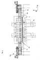
- Fig. 1 shows a plan view of one of the areas of a Bodenmacherzylinders be set or locked in the tube sections.
- two types of devices are needed.
- On the two sides of the bag side grippers 1 a and 1 b are provided. These side grippers 1 a and 1 b grip the lateral ends of the tube portion and set them by a gripping movement, while exerting a force in the radial direction of the cylinder on the axis of rotation of the Bodenmacherzylinders.
- numerous vacuum openings or suction openings 2 and 3 are provided, which additionally attract the hose section and thus improve its fixation on the circumference of the Bodenmacherzylinders.
- the vacuum openings 3a and 3b which are designed to be displaceable in the axial direction of the floor maker cylinder and the vacuum openings 2b fixed in the axial direction are to be distinguished.
- the axially movable suction openings 3a and 3b are displaceable with the slides 1 a and 1b in the axial direction of the Bodenmacherzylinders. This ensures that the suction openings 3a and 3b are located below the desired position of the bag during operation and do not draw any false air. In the stationary suction openings 2 a and 2 b, this can only be guaranteed in a different way.
- These holes are supplied by the running in the axial direction of the Bodenmacherzylinders vacuum line 7 with vacuum.
- This vacuum line 7 receives the negative pressure from the vacuum line 9, which in turn extends in the radial direction of the Bodenmacherzylinders and receives from the radial direction inside the Bodenmacherzylinders the negative pressure or the vacuum. It should be noted that the bore 9 opens at a point in the conduit 7, which is centrally located in the axial direction of the Bodenmacherzylinders.
- the vacuum line 7 supplies, in addition to the bores 3a and 3b connected directly to it, the bores 3a and 3b displaced in the circumferential direction via vacuum lines 11 extending in the circumferential direction.
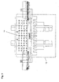
- Figure 2 shows a similar portion of a prior art bottoming cylinder intended to receive a bag.
- the reference numerals are used in the same way as in Figure 1.
- the closure of the same in a format change on narrow tube sections, in which the axially outer openings 2a and 2b must be closed, is independent of a displacement of the gripper.
- the closure of the suction openings is done manually by means of screws which are screwed into the threaded holes designed as suction openings and seal them in this way.
- FIG. 3 again shows two vacuum lines 11 extending in the circumferential direction. Furthermore, by a dashed rectangle, the desired position of a hose section 12 is shown on the bottom maker cylinder. On the representation of the other, extending in the circumferential direction of the vacuum supply lines 11 is omitted for illustrative reasons. Since this line is not visible on a plan view, the vacuum supply lines 11 are shown in dashed lines.
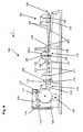
- FIG. 4 shows a sketched side view of a bag machine 135. This figure has been inserted to show the preferred location of installation of devices according to the invention. This is primarily about the description of the core function of such a bag machine, which is in the field of tube section formation and soil preparation. For this purpose, it is again noted at this point that the Bodenmacherzylinder and the Bodenöffner are also explained in the German Auslegeschriften 1611699 and 1080846.
- the bag machine shown in FIG. 4 is supplied with a paper web 100 from right to left in the transport direction of the paper web or of the bag components z.
- the hose forming station 101 which comprises the rollers 102 and also guide the conveyor belt 103, the paper web is folded into a tube 130.
- the finished paper tube 130 is fed to the tear-off unit 131.
- the feed rollers 106 which guide the paper web and lock the paper webs between opposing opposing rollers in opposition. After passing through the nip between the feed rollers, the paper tube is separated from the knife 108, which rotates at the rotating Knife carrier 107 is locked, which leads the knife along the dashed path 107 a, perforated. During the perforation process itself, the counter-pressure cylinder 109 forms an abutment.
- Two knives 108 are attached to the knife carrier 107, so that two cross-sections are formed on the tube web 130 during one revolution of the knife carrier 107.
- the impression cylinder 109 performs during this time two revolutions.
- the pre-perforated tube then enters the nip between the two tear-off cylinders 110, which run faster than the feed rollers 106.
- the tube is torn at the perforation, which takes place between the knife 108 and the nip between the Abr regardingzylindern 110.
- the paper tube is now singulated into paper tube sections 112. These paper tube sections 112 are first transported further by the transport rollers 111.
- the longitudinal cutting station 105 In which a longitudinal section is introduced into the front end of the hose section between the two rollers 116, which is necessary for the subsequent bottoming.
- the tube sections are supplied to the bottom opening station 114, which mainly consists of the bottom opener 113. This is where the floors are opened.
- the aforementioned German Auslegeschrift 1611699 shows such a bottom opener.
- the pieces of hose are fed to the bottom maker cylinder 115, which takes over these and at different processing stations, which are arranged around the Bodenmacherzylinder passes.
- the first of these stations is the bottom folding and gluing station 117. The individual elements of this station are shown only sketched and can be found in the cited references.
- the floors are fixed or pressed in the floor closing station. This is done mainly by the tube sections or bag between the bottom maker cylinder 115 and a press belt 119, which is guided by the rollers 125, are pressed.
- the tube sections or bag 112 then run around a reversing cylinder 120, which ensures that the bags or Move hose sections further from right to left in the direction of transport of bag components z.
- a reversing cylinder 120 In general, provided with finished and fixed floors hose sections are then supplied to other processing stations.
- the bags are often printed and / or provided with carrying handles. At this point, however, the representation of such workstations is omitted. It has also been omitted to show the developments for the paper web 100, which are upstream of the hose forming station 101.
- FIG. 5 once again showed a bag as it can be made in such a bag machine 135.
- This bag 123 has gussets 122.
- FIG. 6 shows a somewhat more advanced bag 121 with carrying handles 124, which have additionally been fixed to the bag with a cover sheet 125.
- Carrying handles and the methods and apparatus for their preparation and attachment to the bag are known in the art and are used for example in the DE 42 05 062 A1 , which was already mentioned at the beginning, shown. As a rule, such carrying handle stations form components of the bag machine which are downstream of the bottom maker cylinder.
- Figure 6 also illustrates once again the design of the bag. So the width and height of the bag is shown again. The height of the bag is determined by the length of tube section defined by the tear-off station.
- the height of the bag or the tube section length is determined primarily by the diameter of the circumferential circle of the knife carrier 107.
- the width results from the width of the paper web and the settings of the hose station 101. Even with width changes extensive changes in the settings of the tools, for example, on the floor maker cylinder must be made.
Landscapes
- Supplying Of Containers To The Packaging Station (AREA)
- Making Paper Articles (AREA)
- Revetment (AREA)
- Air Bags (AREA)
Abstract
Description
Die Erfindung betrifft einen Bodenmacherzylinder einer Beutelmaschine nach dem Oberbegriff des Anspruchs 1.The invention relates to a bottoming cylinder of a bagging machine according to the preamble of
Beutelmaschinen sind bekannt. Sie werden beispielsweise in Schriften
Zum Arretieren der Schlauchabschnitte an dem Bodenmacherzylinder werden sowohl Greifer als auch Vakuumansaugvorrichtungen eingesetzt. Es hat sich als nützlich erwiesen, beide Vorrichtungen gemeinsam an moderneren Beutelmaschinen einzusetzen. An Beutelmaschinen werden häufig alle möglichen Formatwechsel vorgenommen. Zu den möglichen Formatwechseln gehört ein Wechsel in der Breite des herzustellenden Beutels, was natürlich auch eine Änderung in der Breite des zugeführten Papierschlauches beziehungsweise der vereinzelten Papierschlauchabschnitte bedingt. Demzufolge müssen die Haltevorrichtungen, welche die Papierschlauchabschnitte an dem Umfang des Beutelmacherzylinders arretieren, umgestellt werden. Die Umstellung betrifft die Position dieser Haltevorrichtungen in der axialen Richtung des Beutelmacherzylinders, welche in der Regel mit der Breite der späteren Beutel identisch ist. Nach dem Stand der Technik wird vor allem eine aufwändige Einstellung der Vakuumansaugvorrichtungen nötig. Die Vakuumansaugvorrichtungen besitzen in der Regel zahlreiche Öffnungen, welche die von den Beutelabschnitten eingenommene Fläche auf dem Umfang des Beutelmacherzylinders bedecken. Wenn von breiten auf schmale Beutel gewechselt wird, besteht die Gefahr, dass diese Saugöffnungen Falschluft anziehen und auf diese Weise das Vakuum geschwächt wird. Daher sind diese Saugöffnungen in der Regel als Gewindebohrungen ausgeführt, welche mit Schrauben verschlossen werden können. Die Greifer, die in der Lage sind, die Seiten des Beutels zu ergreifen und deswegen "Seitengreifer" genannt werden, werden ebenfalls in der axialen Richtung des Bodenmachers verstellt. Die Umrüstarbeiten sind aufwändig.Both grippers and vacuum suction devices are used to lock the hose sections to the floor maker cylinder. It has proven useful to use both devices together on more modern bagging machines. On bag machines often all possible format changes are made. The possible format changes include a change in the width of the bag to be produced, which of course also causes a change in the width of the supplied paper tube or the individual paper tube sections. Consequently, the holding devices which the Lock the paper tube sections on the circumference of the bag making cylinder, and switch over. The changeover relates to the position of these holding devices in the axial direction of the bag making cylinder, which is generally identical to the width of the later bags. According to the prior art, above all, a complicated adjustment of the vacuum suction devices is necessary. The vacuum aspirators typically have numerous apertures which cover the area occupied by the bag sections on the circumference of the bag maker cylinder. When changing from wide to narrow bags, there is a risk that these suction openings will attract false air and thus weaken the vacuum. Therefore, these suction openings are usually designed as threaded holes, which can be closed with screws. The grippers, which are able to grip the sides of the bag and are therefore called "side grippers", are also adjusted in the axial direction of the ground maker. The conversion work is complex.
Aufgabe der vorliegenden Erfindung ist es daher, diese Umrüstarbeiten zu vereinfachen. Diese Aufgabe wird durch die kennzeichnenden Merkmale des Anspruches 1 gelöst. Bei einer Formatumstellung ist es natürlich möglich, gleich zwei Greifer auf beiden Seiten des Schlauchabschnittes in axialer Richtung des Bodenmachers neu zu justieren. Es ist jedoch ebenso gut möglich, auf die Justage eines Greifers auf einer Seite zu verzichten und lediglich einen Greifer neu einzustellen. Gleiches oder ähnliches gilt natürlich auch für die Vakuumansaugvorrichtungen. Daher beschränkt sich die einfachste Ausführungsform der Erfindung darauf, eine Einstellvorrichtung vorzusehen, mit welcher zumindest ein Greifer und zumindest eine Vakuumsaugvorrichtung gemeinsam auf die Breite der Papierschlauchstücke eingestellt werden kann. Eine vorteilhafte Ausführungsform der Erfindung besitzt eine Vakuumleitung, die gemeinsam mit einem Greifer verschiebbar ist. Dieser Vakuumleitung ist zumindest eine Saugöffnung zugeordnet, die durch die Justagebewegung des Greifers in eine Position unterhalb der Solllage des Beutels gebracht wird. Auf diese Weise lassen sich die zumindest eine Saugöffnung und der Greifer gemeinsam in die neue gewünschte Position bringen. Der Terminus "Vakuumleitungen" wird in der vorliegenden Anmeldung für Unterdruckleitungen, welche die zur Ansaugung der Beutel notwendige Luft bereitstellen, gebraucht.Object of the present invention is therefore to simplify this conversion work. This object is solved by the characterizing features of
Eine andere vorteilhafte Möglichkeit, die Erfindung auszugestalten, welche sich gegebenenfalls auch mit der erstgenannten Möglichkeit gemeinsam verwenden lässt, besteht darin, die Lehre des Anspruchs 3 anzuwenden. Diese bezieht sich auf oft in der Form von Arrays angeordnete Saugöffnungen, welche entlang der Solllagen von Beuteln auf dem Umfang des Bodenmacherzylinders angeordnet sind und welche mit Vakuum beaufschlagt werden. Nun ist es möglich, Absperrmittel vorzusehen, welche gemeinsam mit dem Greifer bewegt werden können und welche die zumindest eine Vakuumleitung, die die Öffnungen mit Vakuum beziehungsweise mit Unterdruck behafteter Luft versorgt, bei ihrer Bewegung verschließen kann. Auf diese Weise kann gewährleistet werden, dass ein Greifer, der von einer Außenstellung auf der in der axialen Richtung des Bodenmacherzylinders in eine innere Stellung bewegt wird, dieser Verschlussmittel mitführt, wobei diese Verschlussmittel nacheinander Vakuumleitungen so verschließen, dass die in axialer Richtung des Bodenmacherzylinders äußeren Saugöffnungen nacheinander verschlossen werden.Another advantageous possibility to design the invention, which may optionally be used together with the first-mentioned possibility, is to apply the teaching of claim 3. This refers to often arranged in the form of arrays suction openings, which are arranged along the desired positions of bags on the circumference of the Bodenmacherzylinders and which are applied with vacuum. It is now possible to provide blocking means which can be moved together with the gripper and which can close the at least one vacuum line, which supplies the openings with vacuum or vacuum-laden air, during their movement. In this way it can be ensured that a gripper, which is moved from an outward position on the in the axial direction of the Bodenmacherzylinders in an inner position, this closure means, said closure means successively close vacuum lines so that the outer in the axial direction of the Bodenmacherzylinders Suction openings are closed one after the other.
Eine vorteilhafte Möglichkeit, diese Lehre auszuführen, besteht darin, dass eine Vakuumleitung eine Mehrzahl von Saugöffnungen versorgt, wobei diese Mehrzahl von Saugöffnungen in der axialen Richtung des Zylinders unterschiedlichen Positionen aufweisen. Daher wird diese Vakuumleitung zumindest teilweise in der axialen Richtung des Zylinders verlaufen. Diese Leitung kann mit einem Stößel verschließbar sein, der in der Leitung gleitet und bei der Einstellung der Position eines Greifes mit diesem verschiebbar ist. In der Regel wird diese Ausführungsform eine Leitung vorsehen, welche sich parallel zu der Einstellrichtung des Greifers erstreckt, so dass der Stößel parallel mit dem Greifer mitgeführt wird. Die Vakuumversorgung dieser Leitung wird daher in der Regel von den in der axialen Richtung des Bodenmacherzylinders im Inneren gelegenen Bereichen kommen.An advantageous possibility to carry out this teaching is that a vacuum line supplies a plurality of suction openings, wherein these plurality of suction openings in the axial direction of the cylinder have different positions. Therefore, this vacuum line will extend at least partially in the axial direction of the cylinder. This line can be closed with a plunger, which slides in the line and is displaceable in adjusting the position of a gripper with this. In general, this embodiment will provide a conduit which extends parallel to the direction of adjustment of the gripper, so that the plunger is carried in parallel with the gripper. The vacuum supply of this line will therefore usually come from the lying in the axial direction of the Bodenmacherzylinders inside areas.
Jedoch ist es auch möglich, eine Vielzahl von radial verlaufenen Leitungen vorzusehen, welche von einem Verschlussmittel sukzessive verschlossen werden, welches in axialer Richtung mit dem Greifer bewegt wird. Insgesamt ist noch einmal zu betonen, dass ein Bodenmacherzylinder in der Regel über mehrere Bereiche verfügt, innerhalb derer Schlauchabschnitte arretiert und von dem Bodenmacherzylinder transportiert werden. Oft transportiert auf diese Weise ein Bodenmacherzylinder vier Schlauchabschnitte gleichzeitig an den Bodenbearbeitungsstationen vorbei. In der Regel werden die Arretierungsmittel, über die ein solcher Bodenmacherzylinder verfügt, gleichartig und in erfindungsgemäßer Weise ausgestattet sein.However, it is also possible to provide a plurality of radially extending lines, which are successively closed by a closure means, which is moved in the axial direction with the gripper. Overall, it should be emphasized once again that a floor maker cylinder generally has several areas within which hose sections are locked and transported by the floor maker cylinder. Often, in this way, a floor maker cylinder transports four sections of hose past the tillage stations simultaneously. In general, the locking means, which has such a Bodenmacherzylinder be similar and equipped in accordance with the invention.
Weitere Details und Ausführungsbeispiele der vorliegenden Erfindung werden in der gegenständlichen Beschreibung und in den Unteransprüchen offenbart.Further details and embodiments of the present invention are disclosed in the instant specification and in the subclaims.
Die einzelnen Figuren zeigen:
- Fig. 1
- Draufsicht auf Arretierungsvorrichtungen eines erfindungsgemäßen Bodenmacherzylinders.
- Fig. 2
- Dieselbe Draufsicht bei einem Bodenmacherzylinder nach dem Stand der Technik.
- Fig. 3
- Draufsicht auf Arretierungsvorrichtungen mit zwei in Umfangsrichtung verlaufende Vakuumleitungen.
- Fig. 4
- Skizzierte Seitenansicht einer Beutelmaschine.
- Fig. 5
- Skizzierte Ansicht eines auf einer solchen Maschine hergestellten Beutels.
- Fig. 6
- Ein solcher Beutel, der zusätzlich mit Handgriffen beaufschlagt ist.
- Fig. 1
- Top view of locking devices of a Bodenmacherzylinders invention.
- Fig. 2
- The same top view in a prior art floor maker cylinder.
- Fig. 3
- Top view of locking devices with two circumferentially extending vacuum lines.
- Fig. 4
- Sketched side view of a bag machine.
- Fig. 5
- Sketched view of a bag made on such a machine.
- Fig. 6
- Such a bag, which is additionally acted upon by handles.
Fig. 1 zeigt eine Draufsicht auf einen der Bereiche eines Bodenmacherzylinders, in dem Schlauchabschnitte festgelegt beziehungsweise arretiert werden. Zur Festlegung diese Schlauchabschnitte werden vorwiegend zwei Arten von Vorrichtungen benötigt. Auf den beiden Seiten des Beutels sind Seitengreifer 1 a und 1 b vorgesehen. Diese Seitengreifer 1 a und 1 b greifen die seitlichen Enden des Schlauchabschnittes und legen sie durch eine Greifbewegung fest, wobei sie eine Kraft in der radialen Richtung des Zylinders auf die Drehachse des Bodenmacherzylinders zu ausüben. Wie bereits erwähnt sind neben diesen Seitengreifern auch zahlreiche Vakuumöffnungen beziehungsweise Saugöffnungen 2 und 3 vorgesehen, welche den Schlauchabschnitt zusätzlich anziehen und so seine Festlegung auf dem Umfang des Bodenmacherzylinders verbessern. In dem gezeigten Ausführungsbeispiel der Erfindung sind die in axialer Richtung des Bodenmacherzylinders verschieblich ausgestalteten Vakuumöffnungen 3a und 3b sowie die in axialer Richtung festliegenden Vakuumöffnungen 2b zu unterscheiden. Die in axialer Richtung beweglichen Saugöffnungen 3a und 3b sind mit den Schiebern 1 a und 1b in axialer Richtung des Bodenmacherzylinders verschieblich. Dadurch wird gewährleistet, dass die Saugöffnungen 3a und 3b im Betrieb unterhalb der Solllage des Beutels befindlich sind und keine Falschluft einziehen. Bei den ortsfesten Saugöffnungen 2a und 2b ist so etwas nur in anderer Weise zu gewährleisten. Diese Bohrungen werden durch die in axialer Richtung des Bodenmacherzylinders verlaufende Vakuumleitung 7 mit Vakuum versorgt. Diese Vakuumleitung 7 erhält den Unterdruck von der Vakuumleitung 9, welche ihrerseits in radialer Richtung des Bodenmacherzylinders verläuft und aus dem in radialer Richtung Inneren des Bodenmacherzylinders den Unterdruck beziehungsweise das Vakuum erhält. Zu beachten ist, dass die Bohrung 9 an einer Stelle in die Leitung 7 einmündet, die in der axialen Richtung des Bodenmacherzylinders zentral gelegen ist. Die Vakuumleitung 7 versorgt neben den direkt an sie angeschlossenen Bohrungen 3a und 3b die im Umfangsrichtung gegen sie verschobenen Bohrungen 3a und 3b über in Umfangsrichtung verlaufende Vakuumleitungen 11. Diese sind nur exemplarisch dargestellt, und die Umfangsrichtung wird durch die Koordinate ϕ in der Figur 1 dargestellt. Zu erwähnen sind noch die Halteverstrebungen des Bodenmacherzylinders 5a und 5b und das Übernahmeblech 4, welches kammförmig ausgeführt ist und auf welchem die Schlauchabschnitte dem Bodenmacherzylinder übergeben werden.Fig. 1 shows a plan view of one of the areas of a Bodenmacherzylinders be set or locked in the tube sections. To define these tube sections mainly two types of devices are needed. On the two sides of the
Die Figur 2 zeigt einen ähnlichen, zur Aufnahme eines Beutels gedachten Abschnitt eines Bodenmacherzylinders nach dem Stand der Technik. Die Bezugszeichen werden in gleicher Weise verwendet wie in Figur 1. Es wird jedoch darauf hingewiesen, dass ausschließlich ortsfeste Ansaugöffnungen 2a und 2b vorhanden sind. Die Verschließung derselben bei einem Formatwechsel auf schmale Schlauchabschnitte, bei der die in axialer Richtung äußeren Öffnungen 2a und 2b verschlossen werden müssen, erfolgt unabhängig von einer Verschiebung der Greifer. Die Verschließung der Saugöffnungen erfolgt manuell mit Hilfe von Schrauben, die in die als Gewindebohrungen ausgestalteten Saugöffnungen eingeschraubt werden und diese auf diese Weise verschließen.Figure 2 shows a similar portion of a prior art bottoming cylinder intended to receive a bag. The reference numerals are used in the same way as in Figure 1. However, it should be noted that only
In Figur 3 sind nochmals zwei in Umfangsrichtung verlaufende Vakuumleitungen 11 dargestellt. Des weiteren ist durch ein gestricheltes Rechteck die Solllage eines Schlauchabschnittes 12 auf dem Bodenmacherzylinder dargestellt. Auf die Darstellung der weiteren, in Umfangsrichtung verlaufenden Vakuumversorgungsleitungen 11 wird aus darstellerischen Gründen verzichtet. Da diese Linie auf einer Draufsicht nicht sichtbar ist, werden die Vakuumversorgungsleitungen 11 gestrichelt dargestellt.FIG. 3 again shows two
Figur 4 zeigt eine skizzierte Seitenansicht einer Beutelmaschine 135. Diese Figur wurde eingefügt, um den bevorzugten Einbauort erfindungsgemäßer Vorrichtungen zu zeigen. Hierbei geht es in ersten Linie um die Beschreibung der Kernfunktion einer solchen Beutelmaschine, die im Bereich der Schlauchabschnittbildung und Bodenmachung besteht. Hierzu wird an dieser Stelle noch einmal angemerkt, dass der Bodenmacherzylinder und der Bodenöffner auch in den deutschen Auslegeschriften 1611699 sowie 1080846 erklärt sind. Der in Figur 4 gezeigten Beutelmaschine wird eine Papierbahn 100 von rechts nach links in der Transportrichtung der Papierbahn beziehungsweise der Beutelbestandteile z zugeführt. In der Schlauchbildungsstation 101, welche die Walzen 102 umfasst wie auch das Transportband 103 führen, wird die Papierbahn zu einem Schlauch 130 zusammengelegt. Dieser Vorgang wird auch durch die Striche 104 symbolisiert, welche die Ränder der Papierbahn bei ihrem Zusammenlegen darstellen. Der fertige Papierschlauch 130 wird dem Abreißwerk 131 zugeführt. Zu diesem Abreißwerk gehören zunächst die Vorzugswalzen 106, welche die Papierbahn führen und die Papierbahnen zwischen gegeneinander in Opposition stehende Vorzugswalzen arretieren. Nach dem Durchlaufen der Walzenspalte zwischen den Vorzugswalzen wird der Papierschlauch von dem Messer 108, welches an dem rotierenden Messerträger 107 arretiert ist, welcher das Messer entlang der gestrichelten Bahn 107a führt, perforiert. Beim Perforationsvorgang selbst bildet der Gegendruckzylinder 109 eine Gegenlage. An dem Messerträger 107 sind zwei Messer 108 angebracht, so dass bei einer Umdrehung des Messerträgers 107 zwei Querschnitte auf der Schlauchbahn 130 entstehen. Der Gegendruckzylinder 109 vollführt während dieser Zeit zwei Umdrehungen. Der vorperforierte Schlauch kommt sodann in den Walzenspalt zwischen den beiden Abreißzylindern 110, welche schneller laufen als die Vorzugswalzen 106. Dadurch wird der Schlauch an der Perforationsstelle abgerissen, was zwischen dem Messer 108 und dem Walzenspalt zwischen den Abreißzylindern 110 erfolgt. Es bleibt anzumerken, dass der Papierschlauch jetzt zu Papierschlauchabschnitten 112 vereinzelt ist. Diese Papierschlauchabschnitte 112 werden zunächst von den Transportwalzen 111 weiter transportiert. Sie erreichen die Längseinschnittstation 105, bei der zwischen den beiden Walzen 116 ein Längsschnitt in das vordere Ende des Schlauchabschnitts eingebracht wird, was zur anschließenden Bodenbildung notwendig ist. Nach der Längseinschnittstation 105 werden die Schlauchabschnitte der Bodenöffnungsstation 114, welche hauptsächlich aus dem Bodenöffner 113 besteht, zugeführt. Hier werden die Böden geöffnet. Wie bereits erwähnt zeigt die vorgenannte deutsche Auslegeschrift 1611699 einen solchen Bodenöffner. Schließlich werden die Schlauchstücke dem Bodenmacherzylinder 115 zugeführt, der diese übernimmt und an verschiedenen Bearbeitungsstationen, welche um den Bodenmacherzylinder angeordnet sind, vorbeiführt. Die erste dieser Station ist die Bodenfaltungs- und -Beleimungsstation 117. Die einzelnen Elemente dieser Station sind nur skizziert dargestellt und können den zitierten Druckschriften entnommen werden. In jedem Fall sind sie dem Fachmann bekannt. Nach Durchlaufen der Bodenfaltungs- und-beleimungsstation werden die Böden in der Bodenschließungsstation fixiert beziehungsweise angepresst. Dieses geschieht hauptsächlich dadurch, dass die Schlauchabschnitte beziehungsweise Beutel zwischen dem Bodenmacherzylinder 115 und einem Pressband 119, welches von den Walzen 125 geführt wird, verpresset werden. Bei der gezeigten Beutelmaschine laufen die Schlauchabschnitte beziehungsweise Beutel 112 dann um einen Umkehrzylinder 120, welcher dafür sorgt, dass sich die Beutel beziehungsweise Schlauchabschnitte weiter von rechts nach links in der Transportrichtung der Beutelbestandteile z bewegen. In der Regel werden die mit fertig gelegten und fixierten Böden versehenen Schlauchabschnitte dann weiteren Bearbeitungsstationen zugeführt. So werden die Beutel oft bedruckt und/oder mit Tragegriffen versehen. An dieser Stelle wird jedoch auf die Darstellung solcher Arbeitsstationen verzichtet. Es wurde ebenfalls darauf verzichtet, die Abwicklungen für die Papierbahn 100, welche der Schlauchbildungsstation 101 vorgelagert sind, zu zeigen.Figure 4 shows a sketched side view of a
Figur 5 zeigte jedoch noch einmal einen Beutel, wie er in einer solchen Beutelmaschine 135 hergestellt werden kann. Dieser Beutel 123 besitzt Seitenfalten 122.However, FIG. 5 once again showed a bag as it can be made in such a
Die Figur 6 zeigt einen etwas fortgeschritteneren Beutel 121 mit Tragegriffen 124, welche zusätzlich mit einem Deckblatt 125 an dem Beutel fixiert worden sind. Auch Tragegriffe und die Verfahren und Vorrichtung zu deren Herstellung und der Anbringung am Beutel sind dem Fachmann bekannt und werden beispielsweise in der
Claims (5)
- Bottom-forming cylinder (5a, 5b) of a bag-making machine• which stops portions (12, 112) of paper tube on its circumference and leads them past processing stations arranged around it,• and which, in order to stop the portions (12, 112) of paper tube, has vacuum suction devices (2a, 2b, 3a, 3b) and side grippers (1a, 1b), which, by using adjusting devices assigned to them, can be adjusted to the width (B) of the portions (112) of paper tube, the latter being transported by the bottom-forming cylinder (5a, 5b) in such a way that the width (B) of the portions (12, 112) of the paper tube extends predominantly in the axial direction (z) of the bottom-forming cylinder (5a, 5b),characterized by
at least one adjusting device, with which at least one side gripper (1a, 1b) and at least one vacuum suction device (2a, 2b, 3a, 3b) can be adjusted jointly to the width of the portions (12, 112) of paper tube. - Bottom-forming cylinder (5a, 5b) according to Claim 1,
characterized in that• by using the at least one adjusting device, a displacement of a gripper in the axial direction of the bottom-forming cylinder (5a, 5b) can be carried out,• and at least one vacuum line (7, 9, 6a, 6b) is provided, which can be displaced together with the side gripper (1a, 1b) and• which has at least one suction opening (2, 3), with which the portions (12, 112) of paper tube can be attracted by suction. - Bottom-forming cylinder (5a, 5b) according to one of the preceding claims,
characterized in that• on the circumferential surface of the bottom-forming cylinder (5a, 5b), at the points provided to pick up the portions (12, 112) of paper tube, a plurality of suction openings (2, 3, 3a, 3b) are provided,• of which at least two suction openings (2, 2a, 2b) have different positions in the axial direction of the cylinder,• and in that these at least two suction openings (2, 2a, 2b) are supplied by at least one vacuum line (7),• and in that this at least one vacuum line (7) can be closed by shut-off means,• which, during the adjustment of the position of a side gripper (1a, 1b), can be displaced with the latter, which means that the vacuum feed to the lines located outside the desired bag format in the axial direction (z) of the cylinder (5a, 5b) can be interrupted. - Bottom-forming cylinder (5a, 5b) according to the preceding claim,
characterized in that• one vacuum line (7, 9, 11) supplies at least two suction openings (2, 2a, 2b) which have different positions in the axial direction of the cylinder (5a, 5b),• in that this vacuum line (7, 9) extends at least partly in the axial direction (z) of the cylinder• and in that this vacuum line (7, 9) can be closed by a plunger, which slides in the vacuum line (7, 9) and, during the adjustment of the position of a side gripper (1a, 1b), can be displaced with the latter. - Method for adjusting the side grippers (1a, 1b) and the vacuum suction devices (2, 2a, 2b, 3a, 3b, 7, 9, 11) of a bottom-forming cylinder (5a, 5b) to the width of the sections (12, 112) of paper tube which are processed to form bags (123) by the bag-making machine (135) to which the bottom-forming cylinder (5a, 5b) belongs,
characterized in that
the axial position of at least one side gripper (1a, 1b) and the extent of the action of at least one vacuum suction device (2, 2a, 2b, 3a, 3b, 7, 9, 11) in the axial direction can be adjusted with one adjustment operation.
Applications Claiming Priority (2)
| Application Number | Priority Date | Filing Date | Title |
|---|---|---|---|
| DE10344155 | 2003-09-22 | ||
| DE10344155A DE10344155A1 (en) | 2003-09-22 | 2003-09-22 | Bottom cylinder of a bag machine |
Publications (3)
| Publication Number | Publication Date |
|---|---|
| EP1516719A2 EP1516719A2 (en) | 2005-03-23 |
| EP1516719A3 EP1516719A3 (en) | 2006-09-13 |
| EP1516719B1 true EP1516719B1 (en) | 2008-01-23 |
Family
ID=34177912
Family Applications (1)
| Application Number | Title | Priority Date | Filing Date |
|---|---|---|---|
| EP04021275A Expired - Lifetime EP1516719B1 (en) | 2003-09-22 | 2004-09-08 | Bottom forming cylinder of a bag making machine |
Country Status (3)
| Country | Link |
|---|---|
| EP (1) | EP1516719B1 (en) |
| AT (1) | ATE384613T1 (en) |
| DE (2) | DE10344155A1 (en) |
Family Cites Families (6)
| Publication number | Priority date | Publication date | Assignee | Title |
|---|---|---|---|---|
| US2126920A (en) * | 1935-03-14 | 1938-08-16 | Potdevin Machine Co | Bag making machine |
| US2450309A (en) * | 1947-01-09 | 1948-09-28 | Allen O Sohn | Side gripper for square bottomed paper bag forming machines |
| DE806312C (en) * | 1949-06-29 | 1951-06-14 | Windmoeller & Hoelscher | Machine for the production of cross-bottom bags |
| DE1611699C2 (en) * | 1967-08-25 | 1975-11-20 | Windmoeller & Hoelscher, 4540 Lengerich | Device for producing the bottoms in a block bottom bag machine |
| DE1813263A1 (en) * | 1968-12-06 | 1970-11-12 | Windmoeller & Hoelscher | Sacking machine for producing cross-bottom sacks that are open on one side |
| FR2210932A5 (en) * | 1972-12-14 | 1974-07-12 | Holweg Const Mec |
-
2003
- 2003-09-22 DE DE10344155A patent/DE10344155A1/en not_active Withdrawn
-
2004
- 2004-09-08 AT AT04021275T patent/ATE384613T1/en active
- 2004-09-08 EP EP04021275A patent/EP1516719B1/en not_active Expired - Lifetime
- 2004-09-08 DE DE502004006022T patent/DE502004006022D1/en not_active Expired - Lifetime
Also Published As
| Publication number | Publication date |
|---|---|
| DE10344155A1 (en) | 2005-04-28 |
| ATE384613T1 (en) | 2008-02-15 |
| EP1516719A2 (en) | 2005-03-23 |
| EP1516719A3 (en) | 2006-09-13 |
| DE502004006022D1 (en) | 2008-03-13 |
Similar Documents
| Publication | Publication Date | Title |
|---|---|---|
| EP1445079B1 (en) | Device for processing printed packaging or similar substrates | |
| EP0553679B1 (en) | Device for removing a sample in a folding device | |
| DE3830084A1 (en) | METHOD AND DEVICE ON A MACHINE FOR THE PRODUCTION OF LETTER COVERS AND THE LIKE FOR FASTENING CLASPS | |
| DE3008633C2 (en) | ||
| EP2323935B1 (en) | Method and device for transporting flat workpieces | |
| DE1532830B1 (en) | Method and machine for the continuous production of carrier bags | |
| WO2020126163A1 (en) | Labelling apparatus for containers | |
| DE602004012202T2 (en) | Method and device for the overlapping of sheets | |
| EP2276613B1 (en) | Needle roller | |
| DE2644995A1 (en) | DEVICE FOR SELF-MANUFACTURING SEWED PRODUCTS | |
| EP1153834B1 (en) | Method for continuously manufacturing infusion bags | |
| EP0586926B1 (en) | Device for cutting and stapling multi-layered printed products in folding machines | |
| EP1516719B1 (en) | Bottom forming cylinder of a bag making machine | |
| EP3875381A1 (en) | Labeling device for containers | |
| DE536459C (en) | Cross cutting and collecting device for rotary printing machines | |
| DE102013014732B4 (en) | Process and device for the production of cross-bottom sacks | |
| DE19932070A1 (en) | Guide for printed copies in rotary printer folder consists of conveyor material, discharge gap between cylinders, guide body swiveling on axle and container | |
| EP2337678B1 (en) | Device and method for opening ends of hose pieces to form open bottom squares | |
| WO2009121542A1 (en) | Device and method for producing bags from pieces of tubing | |
| EP1525976B1 (en) | Bottom closing device in a bag making machine | |
| DE1761880B1 (en) | Method and device for applying paper or plastic handles to a material web | |
| EP1516718B1 (en) | Bottom opening station in a paper bag apparatus | |
| DE1561434B2 (en) | METHOD OF CONTINUOUSLY MANUFACTURING CARRYING BAGS OR BAGS WITH TWO HANDLES AND MACHINE FOR EXECUTING THE PROCESS | |
| EP3398891B1 (en) | Device for producing collections of sheet-shaped printed products, and corresponding folding apparatus for folding collections of sheet-shaped printed products | |
| DE836431C (en) | Machine for manufacturing and printing flat bags |
Legal Events
| Date | Code | Title | Description |
|---|---|---|---|
| PUAI | Public reference made under article 153(3) epc to a published international application that has entered the european phase |
Free format text: ORIGINAL CODE: 0009012 |
|
| AK | Designated contracting states |
Kind code of ref document: A2 Designated state(s): AT BE BG CH CY CZ DE DK EE ES FI FR GB GR HU IE IT LI LU MC NL PL PT RO SE SI SK TR |
|
| AX | Request for extension of the european patent |
Extension state: AL HR LT LV MK |
|
| PUAL | Search report despatched |
Free format text: ORIGINAL CODE: 0009013 |
|
| AK | Designated contracting states |
Kind code of ref document: A3 Designated state(s): AT BE BG CH CY CZ DE DK EE ES FI FR GB GR HU IE IT LI LU MC NL PL PT RO SE SI SK TR |
|
| AX | Request for extension of the european patent |
Extension state: AL HR LT LV MK |
|
| 17P | Request for examination filed |
Effective date: 20070313 |
|
| AKX | Designation fees paid |
Designated state(s): AT BE BG CH CY CZ DE DK EE ES FI FR GB GR HU IE IT LI LU MC NL PL PT RO SE SI SK TR |
|
| GRAP | Despatch of communication of intention to grant a patent |
Free format text: ORIGINAL CODE: EPIDOSNIGR1 |
|
| GRAS | Grant fee paid |
Free format text: ORIGINAL CODE: EPIDOSNIGR3 |
|
| GRAA | (expected) grant |
Free format text: ORIGINAL CODE: 0009210 |
|
| AK | Designated contracting states |
Kind code of ref document: B1 Designated state(s): AT BE BG CH CY CZ DE DK EE ES FI FR GB GR HU IE IT LI LU MC NL PL PT RO SE SI SK TR |
|
| REG | Reference to a national code |
Ref country code: GB Ref legal event code: FG4D Free format text: NOT ENGLISH |
|
| REG | Reference to a national code |
Ref country code: CH Ref legal event code: EP |
|
| REG | Reference to a national code |
Ref country code: IE Ref legal event code: FG4D Free format text: LANGUAGE OF EP DOCUMENT: GERMAN |
|
| REF | Corresponds to: |
Ref document number: 502004006022 Country of ref document: DE Date of ref document: 20080313 Kind code of ref document: P |
|
| GBT | Gb: translation of ep patent filed (gb section 77(6)(a)/1977) |
Effective date: 20080410 |
|
| NLV1 | Nl: lapsed or annulled due to failure to fulfill the requirements of art. 29p and 29m of the patents act | ||
| PG25 | Lapsed in a contracting state [announced via postgrant information from national office to epo] |
Ref country code: FI Free format text: LAPSE BECAUSE OF FAILURE TO SUBMIT A TRANSLATION OF THE DESCRIPTION OR TO PAY THE FEE WITHIN THE PRESCRIBED TIME-LIMIT Effective date: 20080123 Ref country code: ES Free format text: LAPSE BECAUSE OF FAILURE TO SUBMIT A TRANSLATION OF THE DESCRIPTION OR TO PAY THE FEE WITHIN THE PRESCRIBED TIME-LIMIT Effective date: 20080504 |
|
| PG25 | Lapsed in a contracting state [announced via postgrant information from national office to epo] |
Ref country code: BG Free format text: LAPSE BECAUSE OF FAILURE TO SUBMIT A TRANSLATION OF THE DESCRIPTION OR TO PAY THE FEE WITHIN THE PRESCRIBED TIME-LIMIT Effective date: 20080423 |
|
| PG25 | Lapsed in a contracting state [announced via postgrant information from national office to epo] |
Ref country code: SI Free format text: LAPSE BECAUSE OF FAILURE TO SUBMIT A TRANSLATION OF THE DESCRIPTION OR TO PAY THE FEE WITHIN THE PRESCRIBED TIME-LIMIT Effective date: 20080123 Ref country code: PL Free format text: LAPSE BECAUSE OF FAILURE TO SUBMIT A TRANSLATION OF THE DESCRIPTION OR TO PAY THE FEE WITHIN THE PRESCRIBED TIME-LIMIT Effective date: 20080123 Ref country code: PT Free format text: LAPSE BECAUSE OF FAILURE TO SUBMIT A TRANSLATION OF THE DESCRIPTION OR TO PAY THE FEE WITHIN THE PRESCRIBED TIME-LIMIT Effective date: 20080623 |
|
| PG25 | Lapsed in a contracting state [announced via postgrant information from national office to epo] |
Ref country code: SE Free format text: LAPSE BECAUSE OF FAILURE TO SUBMIT A TRANSLATION OF THE DESCRIPTION OR TO PAY THE FEE WITHIN THE PRESCRIBED TIME-LIMIT Effective date: 20080423 Ref country code: DK Free format text: LAPSE BECAUSE OF FAILURE TO SUBMIT A TRANSLATION OF THE DESCRIPTION OR TO PAY THE FEE WITHIN THE PRESCRIBED TIME-LIMIT Effective date: 20080123 Ref country code: CZ Free format text: LAPSE BECAUSE OF FAILURE TO SUBMIT A TRANSLATION OF THE DESCRIPTION OR TO PAY THE FEE WITHIN THE PRESCRIBED TIME-LIMIT Effective date: 20080123 Ref country code: SK Free format text: LAPSE BECAUSE OF FAILURE TO SUBMIT A TRANSLATION OF THE DESCRIPTION OR TO PAY THE FEE WITHIN THE PRESCRIBED TIME-LIMIT Effective date: 20080123 Ref country code: NL Free format text: LAPSE BECAUSE OF FAILURE TO SUBMIT A TRANSLATION OF THE DESCRIPTION OR TO PAY THE FEE WITHIN THE PRESCRIBED TIME-LIMIT Effective date: 20080123 |
|
| EN | Fr: translation not filed | ||
| PG25 | Lapsed in a contracting state [announced via postgrant information from national office to epo] |
Ref country code: RO Free format text: LAPSE BECAUSE OF FAILURE TO SUBMIT A TRANSLATION OF THE DESCRIPTION OR TO PAY THE FEE WITHIN THE PRESCRIBED TIME-LIMIT Effective date: 20080123 |
|
| PLBE | No opposition filed within time limit |
Free format text: ORIGINAL CODE: 0009261 |
|
| STAA | Information on the status of an ep patent application or granted ep patent |
Free format text: STATUS: NO OPPOSITION FILED WITHIN TIME LIMIT |
|
| 26N | No opposition filed |
Effective date: 20081024 |
|
| BERE | Be: lapsed |
Owner name: WINDMOLLER & HOLSCHER K.G. Effective date: 20080930 |
|
| PG25 | Lapsed in a contracting state [announced via postgrant information from national office to epo] |
Ref country code: EE Free format text: LAPSE BECAUSE OF FAILURE TO SUBMIT A TRANSLATION OF THE DESCRIPTION OR TO PAY THE FEE WITHIN THE PRESCRIBED TIME-LIMIT Effective date: 20080123 Ref country code: MC Free format text: LAPSE BECAUSE OF NON-PAYMENT OF DUE FEES Effective date: 20080930 Ref country code: FR Free format text: LAPSE BECAUSE OF FAILURE TO SUBMIT A TRANSLATION OF THE DESCRIPTION OR TO PAY THE FEE WITHIN THE PRESCRIBED TIME-LIMIT Effective date: 20081114 |
|
| REG | Reference to a national code |
Ref country code: CH Ref legal event code: PL |
|
| PG25 | Lapsed in a contracting state [announced via postgrant information from national office to epo] |
Ref country code: BE Free format text: LAPSE BECAUSE OF NON-PAYMENT OF DUE FEES Effective date: 20080930 Ref country code: CY Free format text: LAPSE BECAUSE OF FAILURE TO SUBMIT A TRANSLATION OF THE DESCRIPTION OR TO PAY THE FEE WITHIN THE PRESCRIBED TIME-LIMIT Effective date: 20080123 |
|
| PG25 | Lapsed in a contracting state [announced via postgrant information from national office to epo] |
Ref country code: CH Free format text: LAPSE BECAUSE OF NON-PAYMENT OF DUE FEES Effective date: 20080930 Ref country code: LI Free format text: LAPSE BECAUSE OF NON-PAYMENT OF DUE FEES Effective date: 20080930 |
|
| PG25 | Lapsed in a contracting state [announced via postgrant information from national office to epo] |
Ref country code: HU Free format text: LAPSE BECAUSE OF FAILURE TO SUBMIT A TRANSLATION OF THE DESCRIPTION OR TO PAY THE FEE WITHIN THE PRESCRIBED TIME-LIMIT Effective date: 20080724 Ref country code: LU Free format text: LAPSE BECAUSE OF NON-PAYMENT OF DUE FEES Effective date: 20080908 |
|
| PG25 | Lapsed in a contracting state [announced via postgrant information from national office to epo] |
Ref country code: TR Free format text: LAPSE BECAUSE OF FAILURE TO SUBMIT A TRANSLATION OF THE DESCRIPTION OR TO PAY THE FEE WITHIN THE PRESCRIBED TIME-LIMIT Effective date: 20080123 |
|
| PG25 | Lapsed in a contracting state [announced via postgrant information from national office to epo] |
Ref country code: GR Free format text: LAPSE BECAUSE OF FAILURE TO SUBMIT A TRANSLATION OF THE DESCRIPTION OR TO PAY THE FEE WITHIN THE PRESCRIBED TIME-LIMIT Effective date: 20080424 |
|
| PGFP | Annual fee paid to national office [announced via postgrant information from national office to epo] |
Ref country code: IE Payment date: 20110912 Year of fee payment: 8 |
|
| PGFP | Annual fee paid to national office [announced via postgrant information from national office to epo] |
Ref country code: AT Payment date: 20110826 Year of fee payment: 8 |
|
| REG | Reference to a national code |
Ref country code: AT Ref legal event code: MM01 Ref document number: 384613 Country of ref document: AT Kind code of ref document: T Effective date: 20120908 |
|
| REG | Reference to a national code |
Ref country code: IE Ref legal event code: MM4A |
|
| PG25 | Lapsed in a contracting state [announced via postgrant information from national office to epo] |
Ref country code: AT Free format text: LAPSE BECAUSE OF NON-PAYMENT OF DUE FEES Effective date: 20120908 Ref country code: IE Free format text: LAPSE BECAUSE OF NON-PAYMENT OF DUE FEES Effective date: 20120908 |
|
| REG | Reference to a national code |
Ref country code: DE Ref legal event code: R079 Ref document number: 502004006022 Country of ref document: DE Free format text: PREVIOUS MAIN CLASS: B31B0029000000 Ipc: B31B0070000000 |
|
| PGFP | Annual fee paid to national office [announced via postgrant information from national office to epo] |
Ref country code: GB Payment date: 20180928 Year of fee payment: 15 |
|
| PGFP | Annual fee paid to national office [announced via postgrant information from national office to epo] |
Ref country code: DE Payment date: 20180930 Year of fee payment: 15 |
|
| PGFP | Annual fee paid to national office [announced via postgrant information from national office to epo] |
Ref country code: IT Payment date: 20180927 Year of fee payment: 15 |
|
| REG | Reference to a national code |
Ref country code: DE Ref legal event code: R119 Ref document number: 502004006022 Country of ref document: DE |
|
| PG25 | Lapsed in a contracting state [announced via postgrant information from national office to epo] |
Ref country code: DE Free format text: LAPSE BECAUSE OF NON-PAYMENT OF DUE FEES Effective date: 20200401 |
|
| PG25 | Lapsed in a contracting state [announced via postgrant information from national office to epo] |
Ref country code: IT Free format text: LAPSE BECAUSE OF NON-PAYMENT OF DUE FEES Effective date: 20190908 |
|
| GBPC | Gb: european patent ceased through non-payment of renewal fee |
Effective date: 20190908 |
|
| PG25 | Lapsed in a contracting state [announced via postgrant information from national office to epo] |
Ref country code: GB Free format text: LAPSE BECAUSE OF NON-PAYMENT OF DUE FEES Effective date: 20190908 |