EP1525947A1 - Method for finish-polishing - Google Patents
Method for finish-polishing Download PDFInfo
- Publication number
- EP1525947A1 EP1525947A1 EP03292647A EP03292647A EP1525947A1 EP 1525947 A1 EP1525947 A1 EP 1525947A1 EP 03292647 A EP03292647 A EP 03292647A EP 03292647 A EP03292647 A EP 03292647A EP 1525947 A1 EP1525947 A1 EP 1525947A1
- Authority
- EP
- European Patent Office
- Prior art keywords
- polishing
- finishing
- polished
- polishing element
- deformable
- Prior art date
- Legal status (The legal status is an assumption and is not a legal conclusion. Google has not performed a legal analysis and makes no representation as to the accuracy of the status listed.)
- Granted
Links
- 238000005498 polishing Methods 0.000 title claims abstract description 79
- 238000000034 method Methods 0.000 title claims abstract description 28
- 239000000463 material Substances 0.000 claims abstract description 25
- 230000005855 radiation Effects 0.000 claims abstract description 4
- 239000000853 adhesive Substances 0.000 claims abstract description 3
- 230000001070 adhesive effect Effects 0.000 claims abstract description 3
- VYPSYNLAJGMNEJ-UHFFFAOYSA-N Silicium dioxide Chemical compound O=[Si]=O VYPSYNLAJGMNEJ-UHFFFAOYSA-N 0.000 claims description 9
- PXHVJJICTQNCMI-UHFFFAOYSA-N Nickel Chemical compound [Ni] PXHVJJICTQNCMI-UHFFFAOYSA-N 0.000 claims description 6
- 239000011521 glass Substances 0.000 claims description 6
- 238000007493 shaping process Methods 0.000 claims description 5
- 239000000919 ceramic Substances 0.000 claims description 4
- 238000006073 displacement reaction Methods 0.000 claims description 4
- 229910052710 silicon Inorganic materials 0.000 claims description 4
- 239000010703 silicon Substances 0.000 claims description 4
- 239000000377 silicon dioxide Substances 0.000 claims description 4
- 229910052759 nickel Inorganic materials 0.000 claims description 3
- 239000011505 plaster Substances 0.000 claims description 3
- 238000006116 polymerization reaction Methods 0.000 claims description 2
- 239000011248 coating agent Substances 0.000 claims 1
- 238000000576 coating method Methods 0.000 claims 1
- 229910000420 cerium oxide Inorganic materials 0.000 abstract description 3
- BMMGVYCKOGBVEV-UHFFFAOYSA-N oxo(oxoceriooxy)cerium Chemical compound [Ce]=O.O=[Ce]=O BMMGVYCKOGBVEV-UHFFFAOYSA-N 0.000 abstract description 3
- 238000003825 pressing Methods 0.000 abstract 1
- 238000010438 heat treatment Methods 0.000 description 5
- XUIMIQQOPSSXEZ-UHFFFAOYSA-N Silicon Chemical compound [Si] XUIMIQQOPSSXEZ-UHFFFAOYSA-N 0.000 description 4
- 229910052751 metal Inorganic materials 0.000 description 4
- 239000002184 metal Substances 0.000 description 4
- 230000000295 complement effect Effects 0.000 description 3
- 229910001369 Brass Inorganic materials 0.000 description 2
- 241001639412 Verres Species 0.000 description 2
- 229910052782 aluminium Inorganic materials 0.000 description 2
- XAGFODPZIPBFFR-UHFFFAOYSA-N aluminium Chemical compound [Al] XAGFODPZIPBFFR-UHFFFAOYSA-N 0.000 description 2
- 238000004458 analytical method Methods 0.000 description 2
- 239000010951 brass Substances 0.000 description 2
- 239000006260 foam Substances 0.000 description 2
- 238000009499 grossing Methods 0.000 description 2
- 238000003754 machining Methods 0.000 description 2
- 230000003287 optical effect Effects 0.000 description 2
- 238000007517 polishing process Methods 0.000 description 2
- 229920005830 Polyurethane Foam Polymers 0.000 description 1
- 239000003082 abrasive agent Substances 0.000 description 1
- 239000004411 aluminium Substances 0.000 description 1
- 239000011230 binding agent Substances 0.000 description 1
- 239000008119 colloidal silica Substances 0.000 description 1
- 230000007423 decrease Effects 0.000 description 1
- 230000007547 defect Effects 0.000 description 1
- 229910003460 diamond Inorganic materials 0.000 description 1
- 239000010432 diamond Substances 0.000 description 1
- 239000003292 glue Substances 0.000 description 1
- 238000000227 grinding Methods 0.000 description 1
- 239000007788 liquid Substances 0.000 description 1
- 238000003801 milling Methods 0.000 description 1
- 239000002245 particle Substances 0.000 description 1
- 239000011496 polyurethane foam Substances 0.000 description 1
- 239000011148 porous material Substances 0.000 description 1
- OANVFVBYPNXRLD-UHFFFAOYSA-M propyromazine bromide Chemical compound [Br-].C12=CC=CC=C2SC2=CC=CC=C2N1C(=O)C(C)[N+]1(C)CCCC1 OANVFVBYPNXRLD-UHFFFAOYSA-M 0.000 description 1
- 239000000758 substrate Substances 0.000 description 1
- 229920002994 synthetic fiber Polymers 0.000 description 1
- XLYOFNOQVPJJNP-UHFFFAOYSA-N water Substances O XLYOFNOQVPJJNP-UHFFFAOYSA-N 0.000 description 1
Images

Classifications
-
- B—PERFORMING OPERATIONS; TRANSPORTING
- B24—GRINDING; POLISHING
- B24B—MACHINES, DEVICES, OR PROCESSES FOR GRINDING OR POLISHING; DRESSING OR CONDITIONING OF ABRADING SURFACES; FEEDING OF GRINDING, POLISHING, OR LAPPING AGENTS
- B24B13/00—Machines or devices designed for grinding or polishing optical surfaces on lenses or surfaces of similar shape on other work; Accessories therefor
- B24B13/015—Machines or devices designed for grinding or polishing optical surfaces on lenses or surfaces of similar shape on other work; Accessories therefor of television picture tube viewing panels, headlight reflectors or the like
-
- B—PERFORMING OPERATIONS; TRANSPORTING
- B24—GRINDING; POLISHING
- B24B—MACHINES, DEVICES, OR PROCESSES FOR GRINDING OR POLISHING; DRESSING OR CONDITIONING OF ABRADING SURFACES; FEEDING OF GRINDING, POLISHING, OR LAPPING AGENTS
- B24B13/00—Machines or devices designed for grinding or polishing optical surfaces on lenses or surfaces of similar shape on other work; Accessories therefor
- B24B13/02—Machines or devices designed for grinding or polishing optical surfaces on lenses or surfaces of similar shape on other work; Accessories therefor by means of tools with abrading surfaces corresponding in shape with the lenses to be made
-
- B—PERFORMING OPERATIONS; TRANSPORTING
- B24—GRINDING; POLISHING
- B24B—MACHINES, DEVICES, OR PROCESSES FOR GRINDING OR POLISHING; DRESSING OR CONDITIONING OF ABRADING SURFACES; FEEDING OF GRINDING, POLISHING, OR LAPPING AGENTS
- B24B37/00—Lapping machines or devices; Accessories
Definitions
- the present invention relates to a polishing process finishing a surface with a polishing element and an abrasive.
- a polishing element for example a felt
- a abrasive for example colloidal silica
- the technique generally used consists in sticking the felt on a metal tool by possibly interposing a flexible material such as foam. This technique presents the disadvantage of deforming the surface to be polished, so that the results obtained are not optimal.
- the subject of the present invention is a process which makes it possible to remedy at least part of the problem mentioned above.
- Said material is advantageously deformable by creep and / or curable. It may for example be pitch which is heated to a temperature which allows it to creep and which, after b and before c, is then cooled to obtain a hardening, or else an adhesive which is in the form of a gel which, after b, and before c is cured for example by polymerization or application of a particular ultraviolet radiation.
- the material can also be plaster ..
- the polishing element can be a felt or any material polishing suitable for finishing polishing leading to low roughness (of the order of 1 ⁇ to some A for example).
- the material of polishing is advantageously carried by a polishing support.
- Finishing polishing can in particular be carried out using of a machine ensuring a relative displacement of translation between the element of polishing and the surface to be polished in two perpendicular directions and possibly rotating about an axis parallel to one of said directions perpendicular. Finishing polishing is particularly applicable to cases of surfaces having a generator, the surface being arranged so such that the direction of the generator is parallel to that of the two directions above which is parallel to the axis of rotation.
- the method applies in particular to surfaces that before finishing polishing, have been previously subjected to pre-polishing (or polishing said coarse) and polishing itself.
- the surface has a roughness for example between 3 ⁇ and 15 ⁇ , so after finishing polishing, the roughness can be between 1A and 5A, and more particularly between 1 ⁇ and 3 ⁇ for glass, silica, silicon and ceramic surfaces (see between 1 ⁇ and 2 ⁇ for glass or silica surfaces) and between 3 ⁇ and 5 ⁇ for a nickel surface coated with a metal surface.
- the invention relates to polishing finishing of surfaces with low roughness (including mirrors) whose shape is for example rectangular. It is based on the use of polishing machines having a kinematic with 2 perpendicular linear axes.
- the shapes generated on surfaces can be planes, spheres, cylinders according to their large size (cylinder southern) or their small size (sagittal cylinder), profile mirrors southern elliptical or parabolic, parabolic or elliptical mirrors representing a piece of a mirror of revolution.
- One of the applications of these surfaces is the realization of mirrors used to shape and focus beams of light X emitted by synchrotron or electron laser light sources free.
- This operation if performed in a conventional manner, generally deforms the surface to be polished.
- the felt is directly adhered to the pitch and its creep is used to shape the surface of the felt so that it is complementary to the surface to be polished.
- the shaping is done by heating the pitch, tool or substrate of the surface to be polished, the mold being the surface to be polished itself. This heating is carried out at a temperature of the order of 60 ° C at which the pitch has a viscosity sufficient to deform by fluant without pouring.
- the movements and pressures applied are similar to those used during the polishing itself (step 4 above), that is to say between 5 and 100 g / cm 2 .
- the state of the art normally known for this phase is stick the felt on a metal tool, possibly inserting a flexible material such as foam.
- the advantage of the process according to the invention is to have a hard tool (pitch at a temperature of 20 ° C) having an outline that matches the shape of the surface to be polished.
- the roughness obtained is generally between 1 and 2 ⁇ on glass and silica. It is generally between 1 ⁇ and 3 ⁇ on silicon and ceramics, and between 3 ⁇ and 5 ⁇ on metal surfaces coated with nickel.
- the polishing element 2 (thickness by example between 0.1 mm and 2 mm) is stuck on the pitch 3 which is integral with a support 4 for example cylindrical which serves as a polishing tool.
- the element of polishing 2 may be a porous material such as a felt, especially a microcellular polyurethane foam from RHODES (Bierkeek - Belgium) or a porous synthetic material ("Finishing Pad") of the Company RODEL, or polishing supports (or “drops”) of the Company Buehler.
- the tool 4 After heating the pitch until it gives it a viscosity to flow without flowing (for example by heating it to a temperature of the order of 60 ° C), the tool 4 is pressed on a surface to be polished 6 of the optical part 1 with sufficient pressure so that the deformation by creep of the pitch allows the felt 2 in contact with the surface 6 to marry locally the shape of the surface 6.
- the felt 2 which can be in one or more pieces preferably has a surface equal to, more or less 20% to that of surface 6.
- the pressure P applied during finishing polishing is of the order of 5 to 100 grams / cm 2 .
- Figure 1b illustrates the process in the case of a surface plane or mirror having a generatrix G in the plane of section.
- FIG. 2 represents a machine that can be used to implement finishing polishing process, as well as for the steps previous smoothing, pre-polishing and polishing itself.
- Each of the sliders carries an arm 17 and 18 extending for example in one direction Y perpendicular to the X direction, with height adjustment 17 ', 18' according to Z (perpendicular to X and Y).
- Each arm has a housing 19 and 20 allowing to receive an axis of rotation 21 and 22 of a workpiece carrier 23 carrying the part 1 whose surface 6 must be subjected to finishing polishing.
- Tool 4 is disposed on a support 15 integral with a table 27 having means for translation of the tool 4 and therefore the felt 2 in the direction Y perpendicular to the direction X.
- These translation means are for example slides 26.
- the polishing speeds in each of the X and Y directions can be chosen for example between 0.05 m / s and 0.5 m / s.
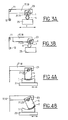
- Figures 3a and 3b on the one hand and 4a and 4b on the other hand illustrate two modes of implementation of finishing polishing (after hardening of the support of deformable material for example pitch or glue).
- the displacement along X (for example between 5 and 200 mm) allows a polishing parallel to the direction of the generatrices of the surface, whereas the translation movement along Y (for example between 1 and 100 mm) and the rotation along the axis (21, 22) allows the surface 6 to be polished to follow while rotating the polishing element 2 as it moves along Y.
- the combination of these three movements ensures the polishing of the surface on its contour and on all its length.
- the part 1 of cylindrical section or plane is carried by the workpiece holder 23 and the tool 4 is secured to the support 25.
- the cylindrical or plane part 1 is integral with the support 25 and it is the tool 4 which is carried by the holder 23.
- the method also applies to surfaces presenting no generator.
- the formatting of element 2 improves the performance relative to the surface with the nearest generator.
Abstract
Description
La présente invention a pour objet un procédé de polissage de finition d'une surface à l'aide d'un élément de polissage et d'un abrasif.The present invention relates to a polishing process finishing a surface with a polishing element and an abrasive.
Il est déjà connu de réaliser un polissage de finition d'une surface à l'aide d'un élément de polissage, par exemple un feutre, et d'un abrasif, par exemple de la silice colloïdale. La technique généralement utilisée consiste à coller le feutre sur un outil métallique en intercalant éventuellement un matériau souple par exemple de type mousse. Cette technique présente l'inconvénient de déformer la surface à polir, ce qui fait que les résultats obtenus ne sont pas optimaux.It is already known to perform a finishing polishing of a surface using a polishing element, for example a felt, and a abrasive, for example colloidal silica. The technique generally used consists in sticking the felt on a metal tool by possibly interposing a flexible material such as foam. This technique presents the disadvantage of deforming the surface to be polished, so that the results obtained are not optimal.
La présente invention a pour objet un procédé qui permette de remédier au moins en partie au problème précité.The subject of the present invention is a process which makes it possible to remedy at least part of the problem mentioned above.
L'invention concerne ainsi un procédé de polissage de finition
d'une surface à l'aide d'un élément de polissage et d'un abrasif, caractérisé
en ce qu'il met en oeuvre :
Ledit matériau est avantageusement déformable par fluage et/ou durcissable. Il peut s'agir par exemple de poix qui est chauffée à une température qui permet son fluage et qui, après b et avant c, est ensuite refroidie pour obtenir un durcissement, ou bien encore d'une colle qui se présente sous forme d'un gel et qui, après b, et avant c est durcie par exemple par polymérisation ou application d'un rayonnement notamment ultra-violet. Le matériau peut être également du plâtre..Said material is advantageously deformable by creep and / or curable. It may for example be pitch which is heated to a temperature which allows it to creep and which, after b and before c, is then cooled to obtain a hardening, or else an adhesive which is in the form of a gel which, after b, and before c is cured for example by polymerization or application of a particular ultraviolet radiation. The material can also be plaster ..
L'élément de polissage peut être un feutre ou tout matériau de polissage convenant à un polissage de finition conduisant à de faibles rugosités (de l'ordre de 1Å à quelques A par exemple). Le matériau de polissage est avantageusement porté par un support de polissage. The polishing element can be a felt or any material polishing suitable for finishing polishing leading to low roughness (of the order of 1Å to some A for example). The material of polishing is advantageously carried by a polishing support.
Le polissage de finition peut être en particulier réalisé à l'aide d'une machine assurant un déplacement relatif de translation entre l'élément de polissage et la surface à polir selon deux directions perpendiculaires et éventuellement de rotation autour d'un axe parallèle à une desdites directions perpendiculaires. Le polissage de finition s'applique particulièrement bien au cas de surfaces ayant une génératrice, la surface étant disposée de manière telle que la direction de la génératrice soit parallèle à celle des deux directions précitées qui est parallèle à l'axe de rotation.Finishing polishing can in particular be carried out using of a machine ensuring a relative displacement of translation between the element of polishing and the surface to be polished in two perpendicular directions and possibly rotating about an axis parallel to one of said directions perpendicular. Finishing polishing is particularly applicable to cases of surfaces having a generator, the surface being arranged so such that the direction of the generator is parallel to that of the two directions above which is parallel to the axis of rotation.
Le procédé s'applique notamment à des surfaces qui avant polissage de finition, ont été préalablement soumises à un pré-polissage (ou polissage dit grossier) et à un polissage proprement dit.The method applies in particular to surfaces that before finishing polishing, have been previously subjected to pre-polishing (or polishing said coarse) and polishing itself.
Après le polissage proprement dit qui peut être réalisé notamment par toute technique connue, la surface présente une rugosité comprise par exemple entre 3Å et 15Å, alors après polissage de finition, la rugosité peut être comprise entre 1A et 5A, et plus particulièrement entre 1Å et 3Å pour des surfaces en verre, en silice, en silicium et en céramique (voire entre 1Å et 2Å pour des surfaces en verre ou en silice) et entre 3Å et 5Å pour une surface en nickel revêtant une surface métallique.After the actual polishing that can be done by any known technique, the surface has a roughness for example between 3Å and 15Å, so after finishing polishing, the roughness can be between 1A and 5A, and more particularly between 1Å and 3Å for glass, silica, silicon and ceramic surfaces (see between 1Å and 2Å for glass or silica surfaces) and between 3Å and 5Å for a nickel surface coated with a metal surface.
D'autres caractéristiques et avantages de l'invention apparaítront mieux à la lecture de la description ci-après, donnée à titre d'exemple non limitatif, en liaison avec les dessins dans lesquels :
- les figures 1a et 1b illustrent en coupe la mise en oeuvre du procédé de polissage de finition selon l'invention,
- la figure 2 représente une machine assurant le polissage de finition d'une surface dans le cadre de la présente invention et les figures 3a et 3b d'une part et 4a et 4b d'autre part illustrent deux modes de mise en oeuvre de la machine.
- FIGS. 1a and 1b illustrate in section the implementation of the finishing polishing method according to the invention,
- FIG. 2 represents a finishing polishing machine of a surface in the context of the present invention and FIGS. 3a and 3b on the one hand and 4a and 4b on the other hand illustrate two modes of implementation of the machine. .
L'invention se rapporte au polissage de finition de surfaces à basse rugosité (notamment des miroirs) dont la forme est par exemple rectangulaire. Il repose sur l'utilisation de machines de polissage ayant une cinématique à 2 axes linéaires perpendiculaires.The invention relates to polishing finishing of surfaces with low roughness (including mirrors) whose shape is for example rectangular. It is based on the use of polishing machines having a kinematic with 2 perpendicular linear axes.
Les formes générées sur des surfaces peuvent être des plans, des sphères, des cylindres suivant leur grande dimension (cylindre méridional) ou leur petite dimension (cylindre sagittal), des miroirs à profil méridional elliptique ou parabolique, des miroirs paraboliques ou elliptiques représentant un morceau d'un miroir de révolution. The shapes generated on surfaces can be planes, spheres, cylinders according to their large size (cylinder southern) or their small size (sagittal cylinder), profile mirrors southern elliptical or parabolic, parabolic or elliptical mirrors representing a piece of a mirror of revolution.
Une des applications de ces surfaces est la réalisation de miroirs utilisés pour mettre en forme et focaliser les faisceaux de lumière X émis par les sources de lumière de type synchrotron ou laser à électrons libres.One of the applications of these surfaces is the realization of mirrors used to shape and focus beams of light X emitted by synchrotron or electron laser light sources free.
Les différentes étapes sont par exemple :
Cette opération, si elle est réalisée de manière classique, déforme généralement la surface à polir.This operation, if performed in a conventional manner, generally deforms the surface to be polished.
Selon l'invention, on colle directement le feutre sur la poix et
on met à profit son fluage pour mettre en forme la surface du feutre de façon
à ce qu'elle soit complémentaire de la surface à polir. La mise en forme est
effectuée en chauffant la poix, l'outil ou le substrat de la surface à polir, le
moule étant la surface à polir elle-même. Ce chauffage est réalisé à une
température de l'ordre de 60°C à laquelle la poix a une viscosité suffisante
pour se déformer en fluant sans couler. Les mouvements et les pressions
appliqués sont similaires à celles mises en oeuvre lors du polissage
proprement dit (étape 4 ci-dessus), c'est-à-dire entre 5 et 100 g/cm2.According to the invention, the felt is directly adhered to the pitch and its creep is used to shape the surface of the felt so that it is complementary to the surface to be polished. The shaping is done by heating the pitch, tool or substrate of the surface to be polished, the mold being the surface to be polished itself. This heating is carried out at a temperature of the order of 60 ° C at which the pitch has a viscosity sufficient to deform by fluant without pouring. The movements and pressures applied are similar to those used during the polishing itself (
L'état de l'art normalement connu pour cette phase est de coller le feutre sur un outil métallique en intercalant éventuellement un matériau souple de type par exemple mousse. L'avantage du procédé selon l'invention est de disposer d'un outil dur (poix à la température de 20°C) ayant un contour qui épouse la forme de la surface à polir. A ce stade, la rugosité obtenue est généralement comprise entre 1 et 2Å sur les matières de type verre et silice. Elle est généralement comprise entre 1Å et 3Å sur le silicium et les céramiques, et entre 3Å et 5Å sur les surfaces métalliques revêtues de nickel.The state of the art normally known for this phase is stick the felt on a metal tool, possibly inserting a flexible material such as foam. The advantage of the process according to the invention is to have a hard tool (pitch at a temperature of 20 ° C) having an outline that matches the shape of the surface to be polished. At this stage, the roughness obtained is generally between 1 and 2Å on glass and silica. It is generally between 1Å and 3Å on silicon and ceramics, and between 3Å and 5Å on metal surfaces coated with nickel.
Selon la figure 1 a, qui concerne le cas d'une pièce optique 1
à polir qui est un cylindre ou un tore, l'élément de polissage 2 (d'épaisseur par
exemple entre 0,1 mm et 2 mm) est collé sur de la poix 3 qui est solidaire d'un
support 4 par exemple cylindrique qui sert d'outil de polissage. L'élément de
polissage 2 peut être un matériau poreux tel qu'un feutre, notamment une
mousse de polyuréthane microcellulaire de la Société RHODES (Bierkeek -
Belgique) ou un matériau synthétique poreux (« Finishing Pad ») de la Société
RODEL, ou des supports (ou « drops ») de polissage de la Société
BUEHLER. Après chauffage de la poix jusqu'à lui conférer une viscosité lui
permettant de fluer sans couler (par exemple en la chauffant à une
température de l'ordre de 60°C), on appuie l'outil 4 sur une surface à polir 6
de la pièce optique 1 avec une pression suffisante pour que la déformation
par fluage de la poix permette au feutre 2 en contact avec la surface 6
d'épouser localement la forme de la surface 6. Le feutre 2 qui peut être en un
ou plusieurs morceaux a de préférence une surface 5 égale, à plus ou moins
20% à celle de la surface 6.According to Figure 1a, which concerns the case of an
La pression P appliquée lors du polissage de finition est de l'ordre de 5 à 100 grammes/cm2.The pressure P applied during finishing polishing is of the order of 5 to 100 grams / cm 2 .
La figure 1b illustre le procédé dans le cas d'une surface plane ou d'un miroir ayant une génératrice G dans le plan de coupe.Figure 1b illustrates the process in the case of a surface plane or mirror having a generatrix G in the plane of section.
La figure 2 représente une machine utilisable pour la mise en oeuvre du procédé de polissage de finition, ainsi que pour les étapes précédentes de doucissage, de pré-polissage et de polissage proprement dit.FIG. 2 represents a machine that can be used to implement finishing polishing process, as well as for the steps previous smoothing, pre-polishing and polishing itself.
Elle présente deux barres de coulissement parallèles 11 et 12
le long de laquelle peuvent se translater dans une première direction X deux
coulisseaux 14 et 15 reliés par une barre d'attelage 16. Chacun des
coulisseaux porte un bras 17 et 18 s'étendant par exemple dans une direction
Y perpendiculaire à la direction X, avec un réglage en hauteur 17', 18' selon Z
(perpendiculaire à X et Y). It has two parallel sliding
Chacun des bras présente un logement 19 et 20 permettant
de recevoir un axe de rotation 21 et 22 d'un porte-pièce 23 portant la pièce 1
dont la surface 6 doit être soumise au polissage de finition. L'outil 4 est
disposé sur un support 15 solidaire d'une table 27 présentant des moyens de
translation de l'outil 4 et donc du feutre 2 dans la direction Y perpendiculaire à
la direction X. Ces moyens de translation sont par exemple des glissières 26.Each arm has a
Les vitesses de polissage dans chacune des directions X et Y peuvent être choisies par exemple entre 0,05 m/s et 0,5 m/s.The polishing speeds in each of the X and Y directions can be chosen for example between 0.05 m / s and 0.5 m / s.
Les figures 3a et 3b d'une part et 4a et 4b d'autre part
illustrent deux modes de mise en oeuvre du polissage de finition (après
durcissement du support en matériau déformable par exemple de la poix ou
de la colle). Le déplacement selon X (par exemple entre 5 et 200 mm) permet
un polissage parallèle à la direction des génératrices de la surface, alors que
le mouvement de translation selon Y (par exemple entre 1 et 100 mm) et la
rotation selon l'axe (21, 22) permet à la surface 6 à polir de suivre en tournant
l'élément de polissage 2 au fur et à mesure du déplacement selon Y. Ainsi, la
combinaison de ces trois mouvements (translation X, translation Y et rotation)
permet d'assurer le polissage de la surface sur son contour et sur toute sa
longueur.Figures 3a and 3b on the one hand and 4a and 4b on the other hand
illustrate two modes of implementation of finishing polishing (after
hardening of the support of deformable material for example pitch or
glue). The displacement along X (for example between 5 and 200 mm) allows
a polishing parallel to the direction of the generatrices of the surface, whereas
the translation movement along Y (for example between 1 and 100 mm) and the
rotation along the axis (21, 22) allows the
Selon les figures 3a et 3b, la pièce 1 de section cylindrique ou
plane est portée par le porte-pièce 23 et l'outil 4 est solidaire du support 25.
Selon les figures 4a et 4b, la pièce 1 cylindrique ou plane est solidaire du
support 25 et c'est l'outil 4 qui est porté par le porte-pièce 23.According to FIGS. 3a and 3b, the
Le procédé s'applique également à des surfaces ne
présentant pas de génératrice. La mise en forme de l'élément 2 améliore les
performances par rapport à la surface ayant la génératrice la plus proche.The method also applies to surfaces
presenting no generator. The formatting of
Claims (13)
Priority Applications (6)
| Application Number | Priority Date | Filing Date | Title |
|---|---|---|---|
| DK03292647T DK1525947T3 (en) | 2003-10-23 | 2003-10-23 | Process of final polishing |
| EP03292647A EP1525947B1 (en) | 2003-10-23 | 2003-10-23 | Method for finish-polishing |
| ES03292647T ES2262958T3 (en) | 2003-10-23 | 2003-10-23 | FINISH POLISHING PROCEDURE. |
| AT03292647T ATE322957T1 (en) | 2003-10-23 | 2003-10-23 | PROCESS FOR FINAL POLISHING |
| DE60304579T DE60304579T2 (en) | 2003-10-23 | 2003-10-23 | Process for final polishing |
| US10/705,017 US20050101226A1 (en) | 2003-10-23 | 2003-11-11 | Finishing polishing method |
Applications Claiming Priority (2)
| Application Number | Priority Date | Filing Date | Title |
|---|---|---|---|
| EP03292647A EP1525947B1 (en) | 2003-10-23 | 2003-10-23 | Method for finish-polishing |
| US10/705,017 US20050101226A1 (en) | 2003-10-23 | 2003-11-11 | Finishing polishing method |
Publications (2)
| Publication Number | Publication Date |
|---|---|
| EP1525947A1 true EP1525947A1 (en) | 2005-04-27 |
| EP1525947B1 EP1525947B1 (en) | 2006-04-12 |
Family
ID=34712591
Family Applications (1)
| Application Number | Title | Priority Date | Filing Date |
|---|---|---|---|
| EP03292647A Expired - Lifetime EP1525947B1 (en) | 2003-10-23 | 2003-10-23 | Method for finish-polishing |
Country Status (6)
| Country | Link |
|---|---|
| US (1) | US20050101226A1 (en) |
| EP (1) | EP1525947B1 (en) |
| AT (1) | ATE322957T1 (en) |
| DE (1) | DE60304579T2 (en) |
| DK (1) | DK1525947T3 (en) |
| ES (1) | ES2262958T3 (en) |
Cited By (1)
| Publication number | Priority date | Publication date | Assignee | Title |
|---|---|---|---|---|
| CN109079646A (en) * | 2018-08-10 | 2018-12-25 | 杨斯晨 | A kind of Ceramic manufacturing glaze paint burnishing device |
Families Citing this family (3)
| Publication number | Priority date | Publication date | Assignee | Title |
|---|---|---|---|---|
| US7988534B1 (en) * | 2004-05-19 | 2011-08-02 | Sutton Stephen P | Optical polishing pitch formulations |
| DE102008043600A1 (en) * | 2008-11-10 | 2010-05-12 | Carl Zeiss Smt Ag | Smoothing tool for smoothing optical surfaces within spatial frequency range between one micrometer and two thousand micrometer, has polishing agent carrier made of synthetic, matting-type material |
| TWI584914B (en) | 2013-07-22 | 2017-06-01 | 佳能股份有限公司 | Component manufacturing method and polishing apparatus |
Citations (3)
| Publication number | Priority date | Publication date | Assignee | Title |
|---|---|---|---|---|
| DE3801969A1 (en) * | 1988-01-23 | 1989-07-27 | Zeiss Carl Fa | Method and apparatus for lapping or polishing optical surfaces |
| US20020102925A1 (en) * | 2001-01-30 | 2002-08-01 | Wess Colin H. | Surface polishing method and apparatus |
| FR2843711A1 (en) * | 2002-08-22 | 2004-02-27 | Europ De Systemes Optiques Soc | Workpiece polishing and finishing procedure uses polishing material with abrasive stuck permanently to deformable backing material |
Family Cites Families (12)
| Publication number | Priority date | Publication date | Assignee | Title |
|---|---|---|---|---|
| US1651181A (en) * | 1924-12-06 | 1927-11-29 | Continental Optical Corp | Tool for treating ophthalmic lenses and process of making same |
| US2822647A (en) * | 1955-12-16 | 1958-02-11 | Younger Mfg Company | Method and apparatus for forming bifocal lenses |
| US3583111A (en) * | 1966-08-22 | 1971-06-08 | David Volk | Lens grinding apparatus |
| US3594963A (en) * | 1969-07-17 | 1971-07-27 | Univis Inc | Grinding pad |
| US4979337A (en) * | 1986-10-03 | 1990-12-25 | Duppstadt Arthur G | Polishing tool for contact lenses and associated method |
| US4989316A (en) * | 1987-03-09 | 1991-02-05 | Gerber Scientific Products, Inc. | Method and apparatus for making prescription eyeglass lenses |
| US4974368A (en) * | 1987-03-19 | 1990-12-04 | Canon Kabushiki Kaisha | Polishing apparatus |
| DE3911986A1 (en) * | 1989-04-12 | 1990-10-18 | Benzinger Carl Gmbh & Co | METHOD AND DEVICE FOR MOLDING WORKPIECES |
| US5205083A (en) * | 1991-10-24 | 1993-04-27 | Pettibone Dennis R | Method and apparatus for polishing optical lenses |
| DE4442181C1 (en) * | 1994-11-26 | 1995-10-26 | Loh Optikmaschinen Ag | Tool for fine working of optical lenses |
| KR20020036789A (en) * | 1999-06-25 | 2002-05-16 | 알프레드 엘. 미첼슨 | Polishing of fluoride crystal optical lenses and preforms using cerium oxide for microlithography |
| EP1252622A1 (en) * | 2000-01-05 | 2002-10-30 | Schott Glass Technologies Inc. | Glass substrates for magnetic media and magnetic media based on such glass substrates |
-
2003
- 2003-10-23 AT AT03292647T patent/ATE322957T1/en not_active IP Right Cessation
- 2003-10-23 ES ES03292647T patent/ES2262958T3/en not_active Expired - Lifetime
- 2003-10-23 EP EP03292647A patent/EP1525947B1/en not_active Expired - Lifetime
- 2003-10-23 DK DK03292647T patent/DK1525947T3/en active
- 2003-10-23 DE DE60304579T patent/DE60304579T2/en not_active Expired - Lifetime
- 2003-11-11 US US10/705,017 patent/US20050101226A1/en not_active Abandoned
Patent Citations (3)
| Publication number | Priority date | Publication date | Assignee | Title |
|---|---|---|---|---|
| DE3801969A1 (en) * | 1988-01-23 | 1989-07-27 | Zeiss Carl Fa | Method and apparatus for lapping or polishing optical surfaces |
| US20020102925A1 (en) * | 2001-01-30 | 2002-08-01 | Wess Colin H. | Surface polishing method and apparatus |
| FR2843711A1 (en) * | 2002-08-22 | 2004-02-27 | Europ De Systemes Optiques Soc | Workpiece polishing and finishing procedure uses polishing material with abrasive stuck permanently to deformable backing material |
Cited By (1)
| Publication number | Priority date | Publication date | Assignee | Title |
|---|---|---|---|---|
| CN109079646A (en) * | 2018-08-10 | 2018-12-25 | 杨斯晨 | A kind of Ceramic manufacturing glaze paint burnishing device |
Also Published As
| Publication number | Publication date |
|---|---|
| ATE322957T1 (en) | 2006-04-15 |
| DK1525947T3 (en) | 2006-07-31 |
| DE60304579T2 (en) | 2007-05-10 |
| DE60304579D1 (en) | 2006-05-24 |
| ES2262958T3 (en) | 2006-12-01 |
| EP1525947B1 (en) | 2006-04-12 |
| US20050101226A1 (en) | 2005-05-12 |
Similar Documents
| Publication | Publication Date | Title |
|---|---|---|
| KR102588457B1 (en) | Rectangular substrate for imprint lithography and making method | |
| CA2079276C (en) | Polishing process for optical connector assembly with optical fiber and polishing apparatus | |
| US5683290A (en) | Apparatus for forming a convex tip on a workpiece | |
| CN108188840B (en) | A kind of processing method of curved surface prism | |
| EP1525947B1 (en) | Method for finish-polishing | |
| EP1249307B1 (en) | Toric tool for polishing an optic surface of an atoric lens and polishing method using said tool | |
| JP2003025118A (en) | Diamond tool for cutting | |
| JP3493208B2 (en) | Method of manufacturing plate having flat main surface and method of manufacturing plate having two parallel main surfaces | |
| FR2843711A1 (en) | Workpiece polishing and finishing procedure uses polishing material with abrasive stuck permanently to deformable backing material | |
| JP3240716B2 (en) | Polishing jig for multi-core optical connector | |
| JP3208056B2 (en) | Polishing method for composite materials | |
| JP2001246561A (en) | Micro v-groove machining device and method | |
| JP4269189B2 (en) | Optical element, optical film planarization method, and optical element manufacturing method | |
| JPH11248906A (en) | Lens and optical device using the same | |
| JPH10315112A (en) | Grinding wheel, manufacture of optical fiber guide block manufacturing mold, optical fiber guide block manufacturing mold and manufacture of optical fiber guide block | |
| JP2006218603A (en) | Rod-shaped worked body, its working device and its working method | |
| JP4060902B2 (en) | Composite optical element and method for manufacturing the same | |
| JP3172203B2 (en) | Polishing method for optical device | |
| CN106956213B (en) | Combined finisher and its manufacturing method | |
| JP3467483B2 (en) | Fixed abrasive structure for precision polishing | |
| JP2003266289A (en) | Optical fiber end face polishing method and ferrule used therein | |
| JPH09180389A (en) | Magnetic head slider production device and magnetic head slider production | |
| WO2003000461A1 (en) | Method of polishing optical fiber connector connection end surface, optical structure and coaxial heterogeneous material layer structure and polishing device | |
| JP2000354944A (en) | Convex spherical surface polishing method of ferrule for optical connector | |
| JP3187480B2 (en) | Polishing apparatus and method for polishing a combined body of optical fiber and optical connector |
Legal Events
| Date | Code | Title | Description |
|---|---|---|---|
| PUAI | Public reference made under article 153(3) epc to a published international application that has entered the european phase |
Free format text: ORIGINAL CODE: 0009012 |
|
| AK | Designated contracting states |
Kind code of ref document: A1 Designated state(s): AT BE BG CH CY CZ DE DK EE ES FI FR GB GR HU IE IT LI LU MC NL PT RO SE SI SK TR |
|
| AX | Request for extension of the european patent |
Extension state: AL LT LV MK |
|
| 17P | Request for examination filed |
Effective date: 20050512 |
|
| GRAP | Despatch of communication of intention to grant a patent |
Free format text: ORIGINAL CODE: EPIDOSNIGR1 |
|
| GRAS | Grant fee paid |
Free format text: ORIGINAL CODE: EPIDOSNIGR3 |
|
| AKX | Designation fees paid |
Designated state(s): AT BE BG CH CY CZ DE DK EE ES FI FR GB GR HU IE IT LI LU MC NL PT RO SE SI SK TR |
|
| GRAA | (expected) grant |
Free format text: ORIGINAL CODE: 0009210 |
|
| AK | Designated contracting states |
Kind code of ref document: B1 Designated state(s): AT BE BG CH CY CZ DE DK EE ES FI GB GR HU IE IT LI LU MC NL PT RO SE SI SK TR |
|
| PG25 | Lapsed in a contracting state [announced via postgrant information from national office to epo] |
Ref country code: IT Free format text: LAPSE BECAUSE OF FAILURE TO SUBMIT A TRANSLATION OF THE DESCRIPTION OR TO PAY THE FEE WITHIN THE PRESCRIBED TIME-LIMIT;WARNING: LAPSES OF ITALIAN PATENTS WITH EFFECTIVE DATE BEFORE 2007 MAY HAVE OCCURRED AT ANY TIME BEFORE 2007. THE CORRECT EFFECTIVE DATE MAY BE DIFFERENT FROM THE ONE RECORDED. Effective date: 20060412 Ref country code: RO Free format text: LAPSE BECAUSE OF FAILURE TO SUBMIT A TRANSLATION OF THE DESCRIPTION OR TO PAY THE FEE WITHIN THE PRESCRIBED TIME-LIMIT Effective date: 20060412 Ref country code: AT Free format text: LAPSE BECAUSE OF FAILURE TO SUBMIT A TRANSLATION OF THE DESCRIPTION OR TO PAY THE FEE WITHIN THE PRESCRIBED TIME-LIMIT Effective date: 20060412 Ref country code: SK Free format text: LAPSE BECAUSE OF FAILURE TO SUBMIT A TRANSLATION OF THE DESCRIPTION OR TO PAY THE FEE WITHIN THE PRESCRIBED TIME-LIMIT Effective date: 20060412 Ref country code: SI Free format text: LAPSE BECAUSE OF FAILURE TO SUBMIT A TRANSLATION OF THE DESCRIPTION OR TO PAY THE FEE WITHIN THE PRESCRIBED TIME-LIMIT Effective date: 20060412 Ref country code: CZ Free format text: LAPSE BECAUSE OF FAILURE TO SUBMIT A TRANSLATION OF THE DESCRIPTION OR TO PAY THE FEE WITHIN THE PRESCRIBED TIME-LIMIT Effective date: 20060412 Ref country code: IE Free format text: LAPSE BECAUSE OF FAILURE TO SUBMIT A TRANSLATION OF THE DESCRIPTION OR TO PAY THE FEE WITHIN THE PRESCRIBED TIME-LIMIT Effective date: 20060412 Ref country code: NL Free format text: LAPSE BECAUSE OF FAILURE TO SUBMIT A TRANSLATION OF THE DESCRIPTION OR TO PAY THE FEE WITHIN THE PRESCRIBED TIME-LIMIT Effective date: 20060412 Ref country code: FI Free format text: LAPSE BECAUSE OF FAILURE TO SUBMIT A TRANSLATION OF THE DESCRIPTION OR TO PAY THE FEE WITHIN THE PRESCRIBED TIME-LIMIT Effective date: 20060412 |
|
| REG | Reference to a national code |
Ref country code: GB Ref legal event code: FG4D Free format text: NOT ENGLISH |
|
| REG | Reference to a national code |
Ref country code: CH Ref legal event code: EP |
|
| REF | Corresponds to: |
Ref document number: 60304579 Country of ref document: DE Date of ref document: 20060524 Kind code of ref document: P |
|
| REG | Reference to a national code |
Ref country code: IE Ref legal event code: FG4D Free format text: LANGUAGE OF EP DOCUMENT: FRENCH |
|
| REG | Reference to a national code |
Ref country code: CH Ref legal event code: NV Representative=s name: ISLER & PEDRAZZINI AG |
|
| GBT | Gb: translation of ep patent filed (gb section 77(6)(a)/1977) |
Effective date: 20060626 |
|
| REG | Reference to a national code |
Ref country code: DK Ref legal event code: T3 |
|
| REG | Reference to a national code |
Ref country code: SE Ref legal event code: TRGR |
|
| REG | Reference to a national code |
Ref country code: SE Ref legal event code: RPOT |
|
| PG25 | Lapsed in a contracting state [announced via postgrant information from national office to epo] |
Ref country code: PT Free format text: LAPSE BECAUSE OF FAILURE TO SUBMIT A TRANSLATION OF THE DESCRIPTION OR TO PAY THE FEE WITHIN THE PRESCRIBED TIME-LIMIT Effective date: 20060912 |
|
| NLV1 | Nl: lapsed or annulled due to failure to fulfill the requirements of art. 29p and 29m of the patents act | ||
| PG25 | Lapsed in a contracting state [announced via postgrant information from national office to epo] |
Ref country code: MC Free format text: LAPSE BECAUSE OF NON-PAYMENT OF DUE FEES Effective date: 20061031 |
|
| REG | Reference to a national code |
Ref country code: IE Ref legal event code: FD4D |
|
| REG | Reference to a national code |
Ref country code: ES Ref legal event code: FG2A Ref document number: 2262958 Country of ref document: ES Kind code of ref document: T3 |
|
| PLBE | No opposition filed within time limit |
Free format text: ORIGINAL CODE: 0009261 |
|
| STAA | Information on the status of an ep patent application or granted ep patent |
Free format text: STATUS: NO OPPOSITION FILED WITHIN TIME LIMIT |
|
| 26N | No opposition filed |
Effective date: 20070115 |
|
| REG | Reference to a national code |
Ref country code: CH Ref legal event code: PCAR Free format text: ISLER & PEDRAZZINI AG;POSTFACH 1772;8027 ZUERICH (CH) |
|
| BERE | Be: lapsed |
Owner name: SOC. EUROPEENNE DE SYSTEMES OPTIQUES S.E.S.O. Effective date: 20061031 |
|
| PG25 | Lapsed in a contracting state [announced via postgrant information from national office to epo] |
Ref country code: GR Free format text: LAPSE BECAUSE OF FAILURE TO SUBMIT A TRANSLATION OF THE DESCRIPTION OR TO PAY THE FEE WITHIN THE PRESCRIBED TIME-LIMIT Effective date: 20060713 |
|
| PG25 | Lapsed in a contracting state [announced via postgrant information from national office to epo] |
Ref country code: EE Free format text: LAPSE BECAUSE OF FAILURE TO SUBMIT A TRANSLATION OF THE DESCRIPTION OR TO PAY THE FEE WITHIN THE PRESCRIBED TIME-LIMIT Effective date: 20060412 Ref country code: BG Free format text: LAPSE BECAUSE OF FAILURE TO SUBMIT A TRANSLATION OF THE DESCRIPTION OR TO PAY THE FEE WITHIN THE PRESCRIBED TIME-LIMIT Effective date: 20060712 |
|
| PG25 | Lapsed in a contracting state [announced via postgrant information from national office to epo] |
Ref country code: LU Free format text: LAPSE BECAUSE OF NON-PAYMENT OF DUE FEES Effective date: 20061023 Ref country code: TR Free format text: LAPSE BECAUSE OF FAILURE TO SUBMIT A TRANSLATION OF THE DESCRIPTION OR TO PAY THE FEE WITHIN THE PRESCRIBED TIME-LIMIT Effective date: 20060412 Ref country code: HU Free format text: LAPSE BECAUSE OF FAILURE TO SUBMIT A TRANSLATION OF THE DESCRIPTION OR TO PAY THE FEE WITHIN THE PRESCRIBED TIME-LIMIT Effective date: 20061013 |
|
| PG25 | Lapsed in a contracting state [announced via postgrant information from national office to epo] |
Ref country code: CY Free format text: LAPSE BECAUSE OF FAILURE TO SUBMIT A TRANSLATION OF THE DESCRIPTION OR TO PAY THE FEE WITHIN THE PRESCRIBED TIME-LIMIT Effective date: 20060412 |
|
| PG25 | Lapsed in a contracting state [announced via postgrant information from national office to epo] |
Ref country code: BE Free format text: LAPSE BECAUSE OF FAILURE TO SUBMIT A TRANSLATION OF THE DESCRIPTION OR TO PAY THE FEE WITHIN THE PRESCRIBED TIME-LIMIT Effective date: 20061031 |
|
| PGFP | Annual fee paid to national office [announced via postgrant information from national office to epo] |
Ref country code: GB Payment date: 20100929 Year of fee payment: 8 |
|
| PGFP | Annual fee paid to national office [announced via postgrant information from national office to epo] |
Ref country code: DK Payment date: 20101015 Year of fee payment: 8 |
|
| PGFP | Annual fee paid to national office [announced via postgrant information from national office to epo] |
Ref country code: CH Payment date: 20101025 Year of fee payment: 8 Ref country code: DE Payment date: 20100930 Year of fee payment: 8 |
|
| PGFP | Annual fee paid to national office [announced via postgrant information from national office to epo] |
Ref country code: SE Payment date: 20101014 Year of fee payment: 8 Ref country code: IT Payment date: 20100928 Year of fee payment: 8 |
|
| PGFP | Annual fee paid to national office [announced via postgrant information from national office to epo] |
Ref country code: ES Payment date: 20110516 Year of fee payment: 8 |
|
| REG | Reference to a national code |
Ref country code: CH Ref legal event code: PL |
|
| GBPC | Gb: european patent ceased through non-payment of renewal fee |
Effective date: 20111023 |
|
| REG | Reference to a national code |
Ref country code: DK Ref legal event code: EBP |
|
| REG | Reference to a national code |
Ref country code: SE Ref legal event code: EUG |
|
| PG25 | Lapsed in a contracting state [announced via postgrant information from national office to epo] |
Ref country code: CH Free format text: LAPSE BECAUSE OF NON-PAYMENT OF DUE FEES Effective date: 20111031 Ref country code: LI Free format text: LAPSE BECAUSE OF NON-PAYMENT OF DUE FEES Effective date: 20111031 Ref country code: DE Free format text: LAPSE BECAUSE OF NON-PAYMENT OF DUE FEES Effective date: 20120501 |
|
| REG | Reference to a national code |
Ref country code: DE Ref legal event code: R119 Ref document number: 60304579 Country of ref document: DE Effective date: 20120501 |
|
| PG25 | Lapsed in a contracting state [announced via postgrant information from national office to epo] |
Ref country code: GB Free format text: LAPSE BECAUSE OF NON-PAYMENT OF DUE FEES Effective date: 20111023 Ref country code: IT Free format text: LAPSE BECAUSE OF NON-PAYMENT OF DUE FEES Effective date: 20111023 |
|
| PG25 | Lapsed in a contracting state [announced via postgrant information from national office to epo] |
Ref country code: SE Free format text: LAPSE BECAUSE OF NON-PAYMENT OF DUE FEES Effective date: 20111024 Ref country code: DK Free format text: LAPSE BECAUSE OF NON-PAYMENT OF DUE FEES Effective date: 20111031 |
|
| REG | Reference to a national code |
Ref country code: ES Ref legal event code: FD2A Effective date: 20130606 |
|
| PG25 | Lapsed in a contracting state [announced via postgrant information from national office to epo] |
Ref country code: ES Free format text: LAPSE BECAUSE OF NON-PAYMENT OF DUE FEES Effective date: 20111024 |