EP1525946B1 - Horizontal-Bearbeitungszentrum - Google Patents
Horizontal-Bearbeitungszentrum Download PDFInfo
- Publication number
- EP1525946B1 EP1525946B1 EP04024397A EP04024397A EP1525946B1 EP 1525946 B1 EP1525946 B1 EP 1525946B1 EP 04024397 A EP04024397 A EP 04024397A EP 04024397 A EP04024397 A EP 04024397A EP 1525946 B1 EP1525946 B1 EP 1525946B1
- Authority
- EP
- European Patent Office
- Prior art keywords
- cover
- machining center
- spindle
- tool magazine
- horizontal machining
- Prior art date
- Legal status (The legal status is an assumption and is not a legal conclusion. Google has not performed a legal analysis and makes no representation as to the accuracy of the status listed.)
- Expired - Lifetime
Links
- 238000012423 maintenance Methods 0.000 description 4
- 239000002173 cutting fluid Substances 0.000 description 1
Images


Classifications
-
- B—PERFORMING OPERATIONS; TRANSPORTING
- B23—MACHINE TOOLS; METAL-WORKING NOT OTHERWISE PROVIDED FOR
- B23Q—DETAILS, COMPONENTS, OR ACCESSORIES FOR MACHINE TOOLS, e.g. ARRANGEMENTS FOR COPYING OR CONTROLLING; MACHINE TOOLS IN GENERAL CHARACTERISED BY THE CONSTRUCTION OF PARTICULAR DETAILS OR COMPONENTS; COMBINATIONS OR ASSOCIATIONS OF METAL-WORKING MACHINES, NOT DIRECTED TO A PARTICULAR RESULT
- B23Q11/00—Accessories fitted to machine tools for keeping tools or parts of the machine in good working condition or for cooling work; Safety devices specially combined with or arranged in, or specially adapted for use in connection with, machine tools
- B23Q11/08—Protective coverings for parts of machine tools; Splash guards
- B23Q11/0825—Relatively slidable coverings, e.g. telescopic
-
- Y—GENERAL TAGGING OF NEW TECHNOLOGICAL DEVELOPMENTS; GENERAL TAGGING OF CROSS-SECTIONAL TECHNOLOGIES SPANNING OVER SEVERAL SECTIONS OF THE IPC; TECHNICAL SUBJECTS COVERED BY FORMER USPC CROSS-REFERENCE ART COLLECTIONS [XRACs] AND DIGESTS
- Y10—TECHNICAL SUBJECTS COVERED BY FORMER USPC
- Y10T—TECHNICAL SUBJECTS COVERED BY FORMER US CLASSIFICATION
- Y10T409/00—Gear cutting, milling, or planing
- Y10T409/30—Milling
- Y10T409/30392—Milling with means to protect operative or machine [e.g., guard, safety device, etc.]
-
- Y—GENERAL TAGGING OF NEW TECHNOLOGICAL DEVELOPMENTS; GENERAL TAGGING OF CROSS-SECTIONAL TECHNOLOGIES SPANNING OVER SEVERAL SECTIONS OF THE IPC; TECHNICAL SUBJECTS COVERED BY FORMER USPC CROSS-REFERENCE ART COLLECTIONS [XRACs] AND DIGESTS
- Y10—TECHNICAL SUBJECTS COVERED BY FORMER USPC
- Y10T—TECHNICAL SUBJECTS COVERED BY FORMER US CLASSIFICATION
- Y10T483/00—Tool changing
- Y10T483/11—Tool changing with safety means
- Y10T483/115—Guard
-
- Y—GENERAL TAGGING OF NEW TECHNOLOGICAL DEVELOPMENTS; GENERAL TAGGING OF CROSS-SECTIONAL TECHNOLOGIES SPANNING OVER SEVERAL SECTIONS OF THE IPC; TECHNICAL SUBJECTS COVERED BY FORMER USPC CROSS-REFERENCE ART COLLECTIONS [XRACs] AND DIGESTS
- Y10—TECHNICAL SUBJECTS COVERED BY FORMER USPC
- Y10T—TECHNICAL SUBJECTS COVERED BY FORMER US CLASSIFICATION
- Y10T483/00—Tool changing
- Y10T483/18—Tool transfer to or from matrix
- Y10T483/1873—Indexing matrix
- Y10T483/1891—Chain or belt
Definitions
- the present invention relates to a horizontal machining center according to the preamble of claim 1, as for example known from JP-A-11099427.
- the present invention relates to improvements of a cover structure for a slidable section and the placement of a tool magazine of a horizontal machining center.
- Multitasking machine such as a horizontal machining center
- a cover for preventing intrusion of chips and cutting fluid into a gap between sliding surfaces during cutting of a workpiece.
- the machining center has an automatic tool change unit near the spindle and, thus, has to have a space for accommodating a tool magazine or the like, which leads to a large footprint of the whole machining center.
- a slidable cover for machine tools, such as a lathe, is disclosed in Japanese Patent Laid-Open No. 7-251348
- the present invention provides a horizontal machining center that is reduced in width and enhanced in maintainability through improvements in structure of a cover for an X-axis slidable surface and in placement of a tool magazine and the cover.
- a horizontal machining center essentially comprises: a bed; a table mounted on the bed on which a workpiece is mounted; a column that moves along a guide rail provided on the bed along a horizontal axis; a spindle stock that moves along a guide rail provided on the column along a vertical axis; a spindle attached to the spindle stock in a horizontal position; an automatic tool change unit disposed close to the spindle; and a tool magazine for housing an interchangeable tool, in which a cover disposed between the table and the column comprises a plate-like fixed cover fixed in a vertical plane and a pair of slidable covers supported slidably with respect to the fixed cover, and the cover is disposed with one edge thereof passing through an opening formed in the middle of the tool magazine.
- the slidable covers are mounted or removed at edges of the fixed cover.
- the cover provided in a vertical plane can be disposed with one edge thereof passing through the opening formed in the middle of the tool magazine. Therefore, the whole machine can have a reduced size, and the floor space therefore can be reduced.
- FIG. 1 is a schematic perspective view of a horizontal machining center according to an embodiment of the present invention.
- a horizontal machining center generally denoted by reference numeral 1 has a table 20 on a bed 10, and a workpiece is mounted on the table 20.
- the bed 10 has an X-axis slidable surface (not shown), and a column 30 is mounted on the bed 10 slidably along an X axis.
- the column 30 is driven by a servo motor 32.
- a spindle stock 40 is supported slidably along a Y axis.
- the spindle stock 40 is driven along the Y axis by a servo motor 42.
- a spindle 44 supported by the spindle stock 40 grasps a cutting tool and relatively moves with respect to the table 20 along a Z axis.
- a tool magazine 110 is placed near the bed 10 and the table 20.
- An automatic tool change unit 100 is mounted between the tool magazine 110 and the spindle 44.
- the automatic tool change unit 100 is to remove a tool after use from the spindle 44 and inserts a new tool to the spindle 44.
- a cover 200 for the X-axis slidable surface is mountedbetween the column 30 and the table 20.
- the cover 200 has a plate-like fixed cover 205, which is fixed to the bed 10 at the lower edge thereof.
- the fixed cover 205 is disposed in such a manner that an edge thereof on the side of the tool magazine 110 passes through an opening 150 formed in the middle of the tool magazine 110.
- the cover 200 has a pair of right and left slidable covers 210 that are slidably attached to the fixed cover 205.
- the inner edges of the paired right and left slidable covers 210 are attached to the spindle stock 40, and the slidable covers 210 slide following the movements of the spindle stock 40 along the X axis.
- the spindle stock 40 moves vertically in an opening 220 between the paired right and left slidable covers 210.
- the opening 220 is covered with a Y-axis cover.
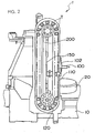
- FIG. 2 is a left side view of the horizontal machining center 1 according to the present invention, which is viewed from the side of the tool magazine.
- the tool magazine 110 incorporates a chain 120 for supporting a tool T.
- a required tool T is positioned at a changing position, and a tool T after use on the spindle 44 is automatically replaced with the required tool T.
- the tool magazine 110 has the opening 150 in the middle thereof.
- the X-axis slidable surface cover 200 is disposed in such a manner that an edge thereof on the side of the tool magazine 110 passes through the opening 150 in the tool magazine.
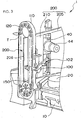
- FIG. 3 is a perspective view of the horizontal machining center 1 according to the present invention, viewed from the side of the tool magazine 110.
- FIG. 3 shows a positional relationship among a tool change arm 102 and the tool magazine 110 of the automatic tool change unit 100 and the spindle 44.
- FIG. 4 is a perspective view of the horizontal machining center 1 according to the present invention, viewed from the back thereof.
- FIG. 4 shows the edge of the X-axis slidable surface cover 200 passing through the opening 150 in the tool magazine 110.
- the paired right and left slidable covers 210 slide along a slide rail received also by the fixed cover 205 and can be removed or mounted at the side edges of the fixed cover.
- FIG. 5 is a cross sectional view of an edge part of the X-axis slidable surface cover 200.
- the X-axis slidable surface cover 200 has a plurality of slidable covers 210 disposed in the fixed cover 205.
- the slidable covers 210 slide at a high speed following the high-speed movements of the column 30 along the X axis.
- the slidable covers repeat such a high-speed movement and stopping and, therefore, require maintenance.
- a side wall 206 provided at the end of the X-axis slidable surface cover 200 is removed, and the slidable covers 210 in the fixed cover 205 are drawn sideward in the direction of the arrow A.
- the edge of the X-axis slidable surface cover 200 on the side of the tool magazine 110 has the same structure.
- the slidable covers 210 can also be readily mounted or removed on the side of the tool magazine 110.
- the horizontal machining center 1 according to the present invention can be have a reduced width D. Therefore, the whole machine can be downsized, and the floor space therefore can be saved. In addition, the accessibility of the X-axis slidable surface cover 200 is improved, so that maintenance can be readily performed.
- the present invention can be utilized for downsizing of multitasking machines, such as a horizontal machining center.
Landscapes
- Engineering & Computer Science (AREA)
- Mechanical Engineering (AREA)
- Automatic Tool Replacement In Machine Tools (AREA)
- Auxiliary Devices For Machine Tools (AREA)
Claims (2)
- Horizontal-Bearbeitungszentrum (1), mit:einem Bett (10);einem Tisch (20), der auf dem Bett (10) montiert ist und auf dem ein Werkstück montiert ist;einer Säule (30), die sich entlang einer Führungsschiene bewegt, die auf dem Bett (10) entlang einer waagerechten Achse ausgebildet ist;einem Spindelstock (40), der sich entlang einer Führungsschiene an der Säule (30) entlang einer vertikalen Achse bewegt;einer Spindel (44) an dem Spindelstock (40) in einer waagerechten Position;einer automatischen Werkzeugwechseleinheit (100) nahe der Spindel (44); undeinem Werkzeugmagazin (110) zur Aufnahme eines auswechselbaren Werkzeugs, gekennzeichnet, durch eine Abdeckung (200) zwischen dem Tisch (10) und der Säule (30), die eine plattenförmige, feste Abdeckung (205), die in einer vertikalen Ebene befestigt ist, und zwei verschiebbare Abdeckungen (210), die gleitend in bezug auf die feste Abdeckung (205) abgestützt sind, umfaßt, und dass die Abdeckung mit einer ihrer Ecken so angeordnet ist, dass sie durch eine Öffnung (150) in der Mitte des Werkzeugmagazins (110) passieren kann.
- Horizontal-Bearbeitungszentrum gemäß Anspruch 1, bei dem die verschiebbaren Abdeckungen (210) montiert oder entfernt sind an Ecken der festen Abdeckung (205).
Applications Claiming Priority (2)
| Application Number | Priority Date | Filing Date | Title |
|---|---|---|---|
| JP2003360982 | 2003-10-21 | ||
| JP2003360982A JP3964851B2 (ja) | 2003-10-21 | 2003-10-21 | 横形マシニングセンタ |
Publications (2)
| Publication Number | Publication Date |
|---|---|
| EP1525946A1 EP1525946A1 (de) | 2005-04-27 |
| EP1525946B1 true EP1525946B1 (de) | 2006-08-02 |
Family
ID=34386482
Family Applications (1)
| Application Number | Title | Priority Date | Filing Date |
|---|---|---|---|
| EP04024397A Expired - Lifetime EP1525946B1 (de) | 2003-10-21 | 2004-10-13 | Horizontal-Bearbeitungszentrum |
Country Status (5)
| Country | Link |
|---|---|
| US (1) | US7063653B2 (de) |
| EP (1) | EP1525946B1 (de) |
| JP (1) | JP3964851B2 (de) |
| CN (1) | CN100553870C (de) |
| DE (1) | DE602004001733T2 (de) |
Families Citing this family (17)
| Publication number | Priority date | Publication date | Assignee | Title |
|---|---|---|---|---|
| JP4745612B2 (ja) * | 2003-01-22 | 2011-08-10 | コマツNtc株式会社 | 工作機械 |
| JP2008149416A (ja) * | 2006-12-19 | 2008-07-03 | Nisshinbo Ind Inc | マシニングセンタ |
| JP2008307724A (ja) | 2007-06-13 | 2008-12-25 | Nisshinbo Ind Inc | ラミネート装置 |
| CN101332561B (zh) * | 2007-06-25 | 2012-11-21 | 鸿富锦精密工业(深圳)有限公司 | 机床 |
| CN101332570A (zh) * | 2007-06-28 | 2008-12-31 | 鸿富锦精密工业(深圳)有限公司 | 机床 |
| CN101332575B (zh) * | 2007-06-28 | 2013-01-09 | 鸿富锦精密工业(深圳)有限公司 | 机床 |
| CN101332574B (zh) * | 2007-06-28 | 2012-11-21 | 鸿富锦精密工业(深圳)有限公司 | 机床 |
| CN101357405B (zh) * | 2007-07-30 | 2010-10-06 | 发得科技工业股份有限公司 | 立式车床的提升式门板结构 |
| JP5014970B2 (ja) * | 2007-12-12 | 2012-08-29 | ヤマザキマザック株式会社 | 複合加工旋盤のワーク搬入・搬出装置 |
| CN102615549B (zh) * | 2012-04-11 | 2013-11-06 | 南京众得利自动化机械有限公司 | 机床切屑防护装置 |
| DE102013108314A1 (de) * | 2013-08-01 | 2015-02-05 | Grob-Werke Gmbh & Co. Kg | Bearbeitungsmaschine |
| EP2929979A1 (de) * | 2014-04-08 | 2015-10-14 | Etxe-Tar, S.A. | Werkzeugmaschine zur mechanischen Bearbeitung von Gestängen |
| CN105458825B (zh) * | 2016-01-26 | 2018-01-02 | 一拖(洛阳)开创装备科技有限公司 | 一种卧式三坐标加工机床的干湿分离防护结构 |
| CN106312650A (zh) * | 2016-08-26 | 2017-01-11 | 北京超同步伺服股份有限公司 | 数控机床刀具快速更换方法及刀库 |
| JP6457450B2 (ja) * | 2016-09-05 | 2019-01-23 | ファナック株式会社 | スライドテーブル装置 |
| CN106926019A (zh) * | 2017-04-25 | 2017-07-07 | 珠海市旺磐精密机械有限公司 | 一种卧式数控加工中心 |
| CN108274248A (zh) * | 2018-01-26 | 2018-07-13 | 宁波江北百吉机械有限公司 | 多面一体加工中心 |
Family Cites Families (13)
| Publication number | Priority date | Publication date | Assignee | Title |
|---|---|---|---|---|
| JPS58165950A (ja) * | 1982-03-24 | 1983-10-01 | Hitachi Seiki Co Ltd | マシニングセンタのカバ−自動開閉装置 |
| JPS6234741A (ja) * | 1985-08-06 | 1987-02-14 | Mazda Motor Corp | マシニングセンタのツ−ル交換装置 |
| JP2782323B2 (ja) * | 1994-03-14 | 1998-07-30 | オークマ株式会社 | 旋盤のz軸摺動面カバー |
| US5624363A (en) * | 1995-02-09 | 1997-04-29 | Brother Kogyo Kabushiki Kaisha | Machine tool having a protective cover |
| JP3310134B2 (ja) * | 1995-05-24 | 2002-07-29 | オークマ株式会社 | 工作機械 |
| US6071220A (en) * | 1996-04-26 | 2000-06-06 | Nippei Toyama Corporation | Tool change device and tool change method |
| JPH10138085A (ja) * | 1996-11-11 | 1998-05-26 | Hookosu Kk | コラム移動形マシンニングセンタ |
| JPH1148083A (ja) * | 1997-08-09 | 1999-02-23 | Hookosu Kk | コラム移動形マシンニングセンタ |
| JPH1199427A (ja) * | 1997-09-29 | 1999-04-13 | Toyoda Mach Works Ltd | 自動工具交換装置を備えた工作機械 |
| JPH11333655A (ja) * | 1998-05-27 | 1999-12-07 | Mori Seiki Co Ltd | 工作機械の自動工具交換装置 |
| JP4880111B2 (ja) * | 2000-10-27 | 2012-02-22 | 株式会社森精機製作所 | 工作機械のパレット交換装置 |
| ITTO20010865A1 (it) * | 2001-09-11 | 2003-03-11 | Comau Spa | Dispositivo per il carico e lo scarico di utensili nel e dal magazzino utensili di una macchina utensile. |
| JP4409867B2 (ja) * | 2003-07-15 | 2010-02-03 | 株式会社森精機製作所 | 工作機械の配索構造 |
-
2003
- 2003-10-21 JP JP2003360982A patent/JP3964851B2/ja not_active Expired - Fee Related
-
2004
- 2004-10-13 DE DE602004001733T patent/DE602004001733T2/de not_active Expired - Lifetime
- 2004-10-13 EP EP04024397A patent/EP1525946B1/de not_active Expired - Lifetime
- 2004-10-14 US US10/965,545 patent/US7063653B2/en not_active Expired - Lifetime
- 2004-10-21 CN CNB2004100882183A patent/CN100553870C/zh not_active Expired - Lifetime
Also Published As
| Publication number | Publication date |
|---|---|
| US20050085358A1 (en) | 2005-04-21 |
| DE602004001733T2 (de) | 2007-08-16 |
| JP3964851B2 (ja) | 2007-08-22 |
| EP1525946A1 (de) | 2005-04-27 |
| CN100553870C (zh) | 2009-10-28 |
| JP2005125421A (ja) | 2005-05-19 |
| US7063653B2 (en) | 2006-06-20 |
| DE602004001733D1 (de) | 2006-09-14 |
| CN1608797A (zh) | 2005-04-27 |
Similar Documents
| Publication | Publication Date | Title |
|---|---|---|
| EP1525946B1 (de) | Horizontal-Bearbeitungszentrum | |
| US6632054B2 (en) | Portal milling machine | |
| US8714535B2 (en) | Universal machine tool including a chip collecting space | |
| EP2745958B1 (de) | Werkzeugmaschine mit drehwerkzeug und fräswerkzeug | |
| US6609448B2 (en) | Headstock guide unit for a machine tool | |
| JP2005103694A (ja) | 工作機械 | |
| EP1762332B1 (de) | Werkzeugmaschine | |
| EP1153682B1 (de) | Werkzeugmaschine | |
| JP4392203B2 (ja) | 工作機械 | |
| EP0985489A2 (de) | Maschine mit zwei Spindelköpfen und Abdeckvorrichtung dafür | |
| US6200247B1 (en) | Machine tool with tool changer | |
| EP1188513B1 (de) | Werkzeugmaschine | |
| JP5375500B2 (ja) | 工作機械 | |
| JPH01146631A (ja) | 立形工作機械におけるテーブルの装架構造 | |
| JP4268841B2 (ja) | 工作機械 | |
| JP4474869B2 (ja) | 旋盤 | |
| KR100441223B1 (ko) | 수직 머시닝 센터 | |
| US11964330B2 (en) | Lathe | |
| CN218427274U (zh) | 一种多通道数控机床 | |
| KR20070004458A (ko) | 선반 | |
| JP4371775B2 (ja) | 工作機械 | |
| JPS6242739B2 (de) | ||
| KR20220124863A (ko) | 공작기계의 atc 도어장치 | |
| JP2001334432A (ja) | 工作機械 | |
| JP2005118890A (ja) | 工作機械 |
Legal Events
| Date | Code | Title | Description |
|---|---|---|---|
| PUAI | Public reference made under article 153(3) epc to a published international application that has entered the european phase |
Free format text: ORIGINAL CODE: 0009012 |
|
| AK | Designated contracting states |
Kind code of ref document: A1 Designated state(s): AT BE BG CH CY CZ DE DK EE ES FI FR GB GR HU IE IT LI LU MC NL PL PT RO SE SI SK TR |
|
| AX | Request for extension of the european patent |
Extension state: AL HR LT LV MK |
|
| 17P | Request for examination filed |
Effective date: 20050520 |
|
| AKX | Designation fees paid |
Designated state(s): DE FR GB IT |
|
| GRAP | Despatch of communication of intention to grant a patent |
Free format text: ORIGINAL CODE: EPIDOSNIGR1 |
|
| GRAS | Grant fee paid |
Free format text: ORIGINAL CODE: EPIDOSNIGR3 |
|
| GRAA | (expected) grant |
Free format text: ORIGINAL CODE: 0009210 |
|
| AK | Designated contracting states |
Kind code of ref document: B1 Designated state(s): DE FR GB IT |
|
| PG25 | Lapsed in a contracting state [announced via postgrant information from national office to epo] |
Ref country code: IT Free format text: LAPSE BECAUSE OF FAILURE TO SUBMIT A TRANSLATION OF THE DESCRIPTION OR TO PAY THE FEE WITHIN THE PRESCRIBED TIME-LIMIT;WARNING: LAPSES OF ITALIAN PATENTS WITH EFFECTIVE DATE BEFORE 2007 MAY HAVE OCCURRED AT ANY TIME BEFORE 2007. THE CORRECT EFFECTIVE DATE MAY BE DIFFERENT FROM THE ONE RECORDED. Effective date: 20060802 |
|
| REG | Reference to a national code |
Ref country code: GB Ref legal event code: FG4D |
|
| REF | Corresponds to: |
Ref document number: 602004001733 Country of ref document: DE Date of ref document: 20060914 Kind code of ref document: P |
|
| ET | Fr: translation filed | ||
| PLBE | No opposition filed within time limit |
Free format text: ORIGINAL CODE: 0009261 |
|
| STAA | Information on the status of an ep patent application or granted ep patent |
Free format text: STATUS: NO OPPOSITION FILED WITHIN TIME LIMIT |
|
| 26N | No opposition filed |
Effective date: 20070503 |
|
| REG | Reference to a national code |
Ref country code: FR Ref legal event code: PLFP Year of fee payment: 13 |
|
| REG | Reference to a national code |
Ref country code: FR Ref legal event code: PLFP Year of fee payment: 14 |
|
| REG | Reference to a national code |
Ref country code: FR Ref legal event code: PLFP Year of fee payment: 15 |
|
| PGFP | Annual fee paid to national office [announced via postgrant information from national office to epo] |
Ref country code: FR Payment date: 20181022 Year of fee payment: 16 |
|
| PG25 | Lapsed in a contracting state [announced via postgrant information from national office to epo] |
Ref country code: FR Free format text: LAPSE BECAUSE OF NON-PAYMENT OF DUE FEES Effective date: 20191031 Ref country code: IT Free format text: LAPSE BECAUSE OF NON-PAYMENT OF DUE FEES Effective date: 20191013 |
|
| PGFP | Annual fee paid to national office [announced via postgrant information from national office to epo] |
Ref country code: GB Payment date: 20230831 Year of fee payment: 20 |
|
| PGFP | Annual fee paid to national office [announced via postgrant information from national office to epo] |
Ref country code: DE Payment date: 20230830 Year of fee payment: 20 |
|
| REG | Reference to a national code |
Ref country code: DE Ref legal event code: R071 Ref document number: 602004001733 Country of ref document: DE |
|
| REG | Reference to a national code |
Ref country code: GB Ref legal event code: PE20 Expiry date: 20241012 |
|
| PG25 | Lapsed in a contracting state [announced via postgrant information from national office to epo] |
Ref country code: GB Free format text: LAPSE BECAUSE OF EXPIRATION OF PROTECTION Effective date: 20241012 |
|
| PG25 | Lapsed in a contracting state [announced via postgrant information from national office to epo] |
Ref country code: GB Free format text: LAPSE BECAUSE OF EXPIRATION OF PROTECTION Effective date: 20241012 |