EP1525936B1 - Quenouille - Google Patents
Quenouille Download PDFInfo
- Publication number
- EP1525936B1 EP1525936B1 EP04024287A EP04024287A EP1525936B1 EP 1525936 B1 EP1525936 B1 EP 1525936B1 EP 04024287 A EP04024287 A EP 04024287A EP 04024287 A EP04024287 A EP 04024287A EP 1525936 B1 EP1525936 B1 EP 1525936B1
- Authority
- EP
- European Patent Office
- Prior art keywords
- control pin
- pin according
- body member
- wear
- elongate body
- Prior art date
- Legal status (The legal status is an assumption and is not a legal conclusion. Google has not performed a legal analysis and makes no representation as to the accuracy of the status listed.)
- Not-in-force
Links
- 239000011159 matrix material Substances 0.000 claims abstract description 19
- 239000000919 ceramic Substances 0.000 claims abstract description 16
- 229910010293 ceramic material Inorganic materials 0.000 claims abstract description 15
- 239000002131 composite material Substances 0.000 claims abstract description 14
- 229910001338 liquidmetal Inorganic materials 0.000 claims abstract description 14
- 238000005266 casting Methods 0.000 claims abstract description 7
- 239000000463 material Substances 0.000 claims description 35
- VYPSYNLAJGMNEJ-UHFFFAOYSA-N Silicium dioxide Chemical compound O=[Si]=O VYPSYNLAJGMNEJ-UHFFFAOYSA-N 0.000 claims description 27
- 239000004411 aluminium Substances 0.000 claims description 19
- 229910052782 aluminium Inorganic materials 0.000 claims description 19
- XAGFODPZIPBFFR-UHFFFAOYSA-N aluminium Chemical compound [Al] XAGFODPZIPBFFR-UHFFFAOYSA-N 0.000 claims description 19
- 239000004744 fabric Substances 0.000 claims description 19
- 230000003014 reinforcing effect Effects 0.000 claims description 15
- 239000005350 fused silica glass Substances 0.000 claims description 14
- 229910052582 BN Inorganic materials 0.000 claims description 13
- PZNSFCLAULLKQX-UHFFFAOYSA-N Boron nitride Chemical compound N#B PZNSFCLAULLKQX-UHFFFAOYSA-N 0.000 claims description 13
- CPLXHLVBOLITMK-UHFFFAOYSA-N Magnesium oxide Chemical compound [Mg]=O CPLXHLVBOLITMK-UHFFFAOYSA-N 0.000 claims description 12
- MCMNRKCIXSYSNV-UHFFFAOYSA-N Zirconium dioxide Chemical compound O=[Zr]=O MCMNRKCIXSYSNV-UHFFFAOYSA-N 0.000 claims description 12
- 239000011248 coating agent Substances 0.000 claims description 10
- 238000000576 coating method Methods 0.000 claims description 10
- 230000000295 complement effect Effects 0.000 claims description 10
- OKTJSMMVPCPJKN-UHFFFAOYSA-N Carbon Chemical compound [C] OKTJSMMVPCPJKN-UHFFFAOYSA-N 0.000 claims description 9
- 239000000378 calcium silicate Substances 0.000 claims description 9
- 229910052918 calcium silicate Inorganic materials 0.000 claims description 9
- OYACROKNLOSFPA-UHFFFAOYSA-N calcium;dioxido(oxo)silane Chemical compound [Ca+2].[O-][Si]([O-])=O OYACROKNLOSFPA-UHFFFAOYSA-N 0.000 claims description 9
- 239000010439 graphite Substances 0.000 claims description 9
- 229910002804 graphite Inorganic materials 0.000 claims description 9
- QYEXBYZXHDUPRC-UHFFFAOYSA-N B#[Ti]#B Chemical compound B#[Ti]#B QYEXBYZXHDUPRC-UHFFFAOYSA-N 0.000 claims description 8
- 229910033181 TiB2 Inorganic materials 0.000 claims description 8
- 239000000203 mixture Substances 0.000 claims description 8
- XUIMIQQOPSSXEZ-UHFFFAOYSA-N Silicon Chemical compound [Si] XUIMIQQOPSSXEZ-UHFFFAOYSA-N 0.000 claims description 7
- PNEYBMLMFCGWSK-UHFFFAOYSA-N aluminium oxide Inorganic materials [O-2].[O-2].[O-2].[Al+3].[Al+3] PNEYBMLMFCGWSK-UHFFFAOYSA-N 0.000 claims description 7
- 229910052710 silicon Inorganic materials 0.000 claims description 7
- 239000010703 silicon Substances 0.000 claims description 7
- HBMJWWWQQXIZIP-UHFFFAOYSA-N silicon carbide Chemical compound [Si+]#[C-] HBMJWWWQQXIZIP-UHFFFAOYSA-N 0.000 claims description 7
- 229910010271 silicon carbide Inorganic materials 0.000 claims description 7
- 239000010456 wollastonite Substances 0.000 claims description 7
- 229910052882 wollastonite Inorganic materials 0.000 claims description 7
- PIGFYZPCRLYGLF-UHFFFAOYSA-N Aluminum nitride Chemical compound [Al]#N PIGFYZPCRLYGLF-UHFFFAOYSA-N 0.000 claims description 6
- 229910052581 Si3N4 Inorganic materials 0.000 claims description 6
- KZHJGOXRZJKJNY-UHFFFAOYSA-N dioxosilane;oxo(oxoalumanyloxy)alumane Chemical compound O=[Si]=O.O=[Si]=O.O=[Al]O[Al]=O.O=[Al]O[Al]=O.O=[Al]O[Al]=O KZHJGOXRZJKJNY-UHFFFAOYSA-N 0.000 claims description 6
- 239000011521 glass Substances 0.000 claims description 6
- 239000000395 magnesium oxide Substances 0.000 claims description 6
- 229910052863 mullite Inorganic materials 0.000 claims description 6
- HQVNEWCFYHHQES-UHFFFAOYSA-N silicon nitride Chemical compound N12[Si]34N5[Si]62N3[Si]51N64 HQVNEWCFYHHQES-UHFFFAOYSA-N 0.000 claims description 6
- 229910052845 zircon Inorganic materials 0.000 claims description 6
- GFQYVLUOOAAOGM-UHFFFAOYSA-N zirconium(iv) silicate Chemical compound [Zr+4].[O-][Si]([O-])([O-])[O-] GFQYVLUOOAAOGM-UHFFFAOYSA-N 0.000 claims description 6
- 239000000853 adhesive Substances 0.000 claims description 5
- 230000001070 adhesive effect Effects 0.000 claims description 5
- 230000015572 biosynthetic process Effects 0.000 claims description 5
- 239000004568 cement Substances 0.000 claims description 5
- 239000008119 colloidal silica Substances 0.000 claims description 5
- 238000005755 formation reaction Methods 0.000 claims description 5
- 229910017083 AlN Inorganic materials 0.000 claims description 4
- 239000000377 silicon dioxide Substances 0.000 claims description 4
- RTAQQCXQSZGOHL-UHFFFAOYSA-N Titanium Chemical compound [Ti] RTAQQCXQSZGOHL-UHFFFAOYSA-N 0.000 claims description 3
- OYPRJOBELJOOCE-UHFFFAOYSA-N Calcium Chemical compound [Ca] OYPRJOBELJOOCE-UHFFFAOYSA-N 0.000 claims description 2
- 229910052791 calcium Inorganic materials 0.000 claims description 2
- 239000011575 calcium Substances 0.000 claims description 2
- 239000012779 reinforcing material Substances 0.000 abstract 1
- 229910052751 metal Inorganic materials 0.000 description 18
- 239000002184 metal Substances 0.000 description 18
- NBIIXXVUZAFLBC-UHFFFAOYSA-N Phosphoric acid Chemical compound OP(O)(O)=O NBIIXXVUZAFLBC-UHFFFAOYSA-N 0.000 description 8
- 239000011819 refractory material Substances 0.000 description 5
- 239000007787 solid Substances 0.000 description 5
- 238000009736 wetting Methods 0.000 description 5
- 229910000147 aluminium phosphate Inorganic materials 0.000 description 4
- 230000003628 erosive effect Effects 0.000 description 4
- 238000000034 method Methods 0.000 description 4
- 230000035939 shock Effects 0.000 description 4
- 239000000835 fiber Substances 0.000 description 3
- 238000010438 heat treatment Methods 0.000 description 3
- 238000009434 installation Methods 0.000 description 3
- 238000012423 maintenance Methods 0.000 description 3
- 238000004519 manufacturing process Methods 0.000 description 3
- HCHKCACWOHOZIP-UHFFFAOYSA-N Zinc Chemical compound [Zn] HCHKCACWOHOZIP-UHFFFAOYSA-N 0.000 description 2
- 239000007900 aqueous suspension Substances 0.000 description 2
- 230000000903 blocking effect Effects 0.000 description 2
- 238000013461 design Methods 0.000 description 2
- 239000007788 liquid Substances 0.000 description 2
- 239000002002 slurry Substances 0.000 description 2
- 229910052725 zinc Inorganic materials 0.000 description 2
- 239000011701 zinc Substances 0.000 description 2
- 230000002378 acidificating effect Effects 0.000 description 1
- 239000007864 aqueous solution Substances 0.000 description 1
- 238000006243 chemical reaction Methods 0.000 description 1
- 238000004140 cleaning Methods 0.000 description 1
- 230000000052 comparative effect Effects 0.000 description 1
- 238000005336 cracking Methods 0.000 description 1
- 238000005520 cutting process Methods 0.000 description 1
- 238000007872 degassing Methods 0.000 description 1
- 238000000151 deposition Methods 0.000 description 1
- 238000001035 drying Methods 0.000 description 1
- 239000003292 glue Substances 0.000 description 1
- 238000011065 in-situ storage Methods 0.000 description 1
- 239000004615 ingredient Substances 0.000 description 1
- 238000009413 insulation Methods 0.000 description 1
- 238000005058 metal casting Methods 0.000 description 1
- 238000002156 mixing Methods 0.000 description 1
- 238000012986 modification Methods 0.000 description 1
- 230000004048 modification Effects 0.000 description 1
- 230000003647 oxidation Effects 0.000 description 1
- 238000007254 oxidation reaction Methods 0.000 description 1
- 238000012545 processing Methods 0.000 description 1
- 230000001902 propagating effect Effects 0.000 description 1
- 239000011253 protective coating Substances 0.000 description 1
- 238000000926 separation method Methods 0.000 description 1
- 210000003625 skull Anatomy 0.000 description 1
- 239000000243 solution Substances 0.000 description 1
- 229910001220 stainless steel Inorganic materials 0.000 description 1
- 238000003860 storage Methods 0.000 description 1
- 239000000725 suspension Substances 0.000 description 1
- 239000010455 vermiculite Substances 0.000 description 1
- 229910052902 vermiculite Inorganic materials 0.000 description 1
- 235000019354 vermiculite Nutrition 0.000 description 1
- 239000000080 wetting agent Substances 0.000 description 1
- 239000002759 woven fabric Substances 0.000 description 1
Images


Classifications
-
- B—PERFORMING OPERATIONS; TRANSPORTING
- B22—CASTING; POWDER METALLURGY
- B22D—CASTING OF METALS; CASTING OF OTHER SUBSTANCES BY THE SAME PROCESSES OR DEVICES
- B22D41/00—Casting melt-holding vessels, e.g. ladles, tundishes, cups or the like
- B22D41/14—Closures
- B22D41/16—Closures stopper-rod type, i.e. a stopper-rod being positioned downwardly through the vessel and the metal therein, for selective registry with the pouring opening
- B22D41/18—Stopper-rods therefor
Definitions
- the present invention relates to a control pin for controlling the flow of liquid metal in a casting process.
- a control pin for controlling the flow of nonferrous liquid metals such as aluminium and zinc.
- a typical metal casting process is described in US Patent No. 3,111,732 .
- liquid metal is poured through a spout (or “underpour outlet”) into a mould, where the metal freezes to form a billet or slab.
- the flow of metal through the spout is controlled by a control pin (or “flow regulator") that is located within the spout.
- the control pin may be raised to increase the rate of flow of metal through the spout, or lowered to decrease or interrupt the flow of metal.
- Control pins are generally made of a refractory material, which is able to withstand the high temperature of the molten metal. The material must also be hard so as to resist wear on the end of the rod, where it presses against the seat in the spout.
- One of the most commonly used materials is dense fused silica (DFS). This material is quite tough and has good thermal shock characteristics, but silica is wetted and attacked by liquid aluminium and control pins made of this material therefore have to be provided with a non-stick protective coating, for example of boron nitride. This coating has to be reapplied frequently (for example every one or two pouring operations) and such pins therefore have a high maintenance requirement.
- DFS dense fused silica
- DFS is quite tough, it is susceptible to cracking and these cracks tend to propagate through the material during use. This can eventually cause part of the control pin to break away and block the pouring spout. As a precaution against this, a stainless steel wire is sometimes embedded in the DFS material to ensure that even if the control pin breaks, the broken part can still be withdrawn from the spout.
- control pins made of DFS tend to have a high heat capacity and have to be pre-heated prior to commencement of the metal pouring operation, to bring them up to or close to the temperature of the molten metal. This adds considerably to the complexity of the pouring operation and gives rise to the risk of a serious accident when transferring the hot control pin from the pre-heating oven to the spout. If the control pin is not pre-heated, the molten metal can solidify upon contact with the control pin, thus blocking the spout.
- control pin Other materials are sometimes used for the control pin including, for example, cement-based refractories. Such materials are not wetted by the aluminium and therefore suffer less damage and require less maintenance. However, they are fragile and are easily chipped or broken. Further, such pins have a high heat capacity and therefore need pre-heating.
- control pins It is also known to make control pins from graphite.
- graphite suffers from oxidation and erosion at the air-metal interface, which limits the useful life of the control pins made from this material.
- graphite pins like control pins made of DFS or cement-based refractories, graphite pins have a high heat capacity and so require pre-heating.
- Another refractory material described in US 5,880,046 comprises an aqueous solution of phosphoric acid with a mixture of wollastonite and colloidal silica.
- the material is said to have good thermal insulation characteristics and very good behaviour with respect to molten aluminium. However, it is quite soft and therefore not very hard-wearing.
- a control pin for controlling the flow of liquid metal in a casting process, the control pin including an elongate body member and a wear-resistant tip at one end of the elongate body member, the body member being made at least partially of a laminated composite ceramic material that includes multiple layers of a reinforcing fabric embedded within a cast ceramic matrix.
- the invention relates to a control pin for controlling the flow of nonferrous liquid metals such as aluminium and zinc.
- a control pin made of a laminated composite ceramic material is extremely tough owing to the presence of the reinforcing fabric, which prevents cracks propagating through the material. Breakage of the control pin and blocking of the pouring spout is therefore prevented.
- the control pin includes a wear-resistant tip at the lower end of the elongate body member, to reduce erosion by the liquid metal and wear from contact with the spout.
- the composite ceramic material also has good thermal shock characteristics and is not wetted or attacked by liquid aluminium.
- a control pin made of this material therefore has a long life and a low maintenance requirement.
- a control pin made of the composite ceramic material can also have a low heat capacity and so does not have to be pre-heated prior to commencement of the metal pouring operation. This greatly simplifies the pouring operation and provides substantial cost savings and safety benefits.
- the reinforcing fabric comprises a woven fabric, preferably made of glass.
- the composite ceramic material may include between two and 25 layers, and preferably between 4 and 10 layers, of reinforcing fabric.
- the matrix material may be selected from a group comprising fused silica, alumina, mullite, silicon carbide, silicon nitride, silicon aluminium oxy-nitride, zircon, magnesia, zirconia, graphite, calcium silicate, boron nitride (solid BN), aluminium nitride (AlN) and titanium diboride (TiB 2 ), and mixtures of these materials.
- the matrix material is preferably calcium based and may include calcium silicate and silica. More preferably, the matrix material includes Wollastonite and colloidal silica.
- control pin includes a non-stick surface coating, which may include boron nitride, to reduce wetting by the liquid metal and reduce or prevent the depositing of a skin or skull of metal on the surface of the control pin.
- a non-stick surface coating may include boron nitride, to reduce wetting by the liquid metal and reduce or prevent the depositing of a skin or skull of metal on the surface of the control pin.
- the control may be substantially cylindrical and is preferably constructed and arranged to be suspended substantially vertically in use.
- the control pin may have a suspension point at its upper end and a seating at its lower end.
- the elongate body member is preferably at least partially hollow. This reduces the heat capacity of the pin, so that it heats rapidly on contact with the liquid metal, without causing the metal to freeze. It is particularly advantageous for the lower portion of the control pin, which is immersed in the liquid metal, to be hollow.
- the elongate body member may include a circumferential wall having a wall thickness in the range 1-10mm, preferably approximately 5mm, to provide a low heat capacity.
- the wear-resistant tip is preferably inserted at least partially into one end of the elongate body member.
- the elongate body member and the wear-resistant tip have complementary locking formations.
- the complementary locking formations may include complementary recesses on the elongate body member and the wear-resistant tip, which are filled with an adhesive or cement.
- the wear-resistant tip may be made of a ceramic material, and preferably from a material selected from a group comprising fused silica, alumina, mullite, silicon carbide, silicon nitride, silicon aluminium oxy-nitride, zircon, magnesia, zirconia, graphite, calcium silicate, boron nitride, aluminium titanate, aluminium nitride and titanium diboride.
- the tip is made of a non-wetting material with a low coefficient thermal expansion, for example a cement-bonded fused silica refractory.
- the wear-resistant tip is made from a material having a density in the range 1800-3000kg/m 3 , preferably 1900-2500kg/m 3 .
- control pin has a length in the range 200-1000mm (typically 750mm) and a diameter in the range 20-75mm (typically 40mm).
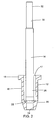
- a typical aluminium casting installation is shown schematically in Figure 1 and includes a furnace 2, from which molten metal flows through a set of launders 4a,4b,4c (or troughs) to a mould 6, which may for example be a direct chill mould. Between the furnace 2 and the mould 6 various additional metal processing units may be provided including, for example, a degassing unit 8 and a filter unit 10. Metal flows from the last launder 4c into the mould 6 through a down spout 12, the flow through the spout being controlled by a control pin 14.
- the down spout 12 and the associated control pin 14 are shown in more detail in Figure 2 .
- the down spout 12 is made of a refractory material such as dense fused silica (DFS) and is conventional in design.
- the spout is tubular, having a cylindrical wall 16 with an axial bore 17 and an outwardly extending flange 18 at its upper end.
- the lower part 20 of the spout has a frusto-conical external shape and internally has a frusto-conical seat 22, leading to a reduced diameter cylindrical bore 24.
- the spout 12 is mounted in the bottom of a launder 4c, so that molten metal within the launder can flow out through the spout.
- the control pin 14 is substantially cylindrical in shape, and in use is suspended vertically so that its lower end 26 is located within the cylindrical body 16 of the outlet spout 12.
- the edge 28 at the lower end of the control pin is bevelled to provide a seal when located against the seat 22 in the spout.
- the upper part 30 of the control pin is of a slightly reduced diameter, and includes a horizontal mounting bore 32 from which the pin is suspended.
- the control pin 14 includes a hollow tubular body member 34 having a hard wear-resistant tip 36 at its lower end.
- the tip 36 has a head 36a that protrudes beyond the end of the tubular body 34, and a body portion 36b that is cemented or otherwise secured within the lower end 26 of the control pin 14.
- the tubular body 34 of the control pin 14 is made of a composite ceramic material that includes numerous layers of a woven fibre reinforcing fabric embedded in a ceramic matrix.
- the woven fibre reinforcing fabric is preferably made of woven glass.
- Various materials may be used for the ceramic matrix, including fused silica, alumina, mullite, silicon carbide, silicon nitride, silicon aluminium oxy-nitride, zircon, magnesia, zirconia, graphite, calcium silicate, boron nitride, aluminium nitride and titanium diboride, or a mixture of these materials.
- the ceramic matrix includes calcium silicate (Wollastonite) and silica and comprises a mouldable refractory composition as described in US Patent No: 5,880,046 , which is sold by Pyrotek, Inc. under the trademark RFM.
- WFM calcium silicate
- the ceramic matrix is made from a composition consisting essentially of 8% to 25% by weight of an aqueous phosphoric acid solution having a concentration of phosphoric acid ranging from 40% to 85% by weight, said phosphoric acid having up to 50% of its primary acidic functions neutralized by reaction with vermiculite; and 75% to 92% by weight of a mixture containing wollastonite and an aqueous suspension containing from 20% to about 40% by weight of colloidal silica, wherein the mixture has a weight ratio of said aqueous suspension to said wollastonite ranging from 0.5 to 1.2.
- the tubular body 34 of the control pin 14 preferably has between 2 and 25 layers of the reinforcing fabric, typically approximately 4 to 10 layers.
- the tip 36 is preferably made of a hard, wear-resistant material that resists erosion from the liquid metal and wear from contact with the spout 12.
- the material also preferably has good resistance to thermal shock, a low density (approx. 1900-2500 kg/m 3 ) and a low coefficient of thermal expansion (approx. 0.7-1.0 x 10 -6 mm/mm/°C). More particularly, the density and thermal expansion values should be similar to those of the matrix material, so that they are well matched.
- the tip 36 may be manufactured from a ceramic material, for example a fused silica refractory, dense fused silica (DFS), alumina, mullite, silicon carbide, silicon nitride, zircon, magnesia, zirconia, graphite, calcium silicate, boron nitride (solid BN), aluminium titanate, aluminium nitride (AlN), titanium diboride (TiB 2 ) or silicon aluminium oxynitride (Sialon).
- a ceramic material for example a fused silica refractory, dense fused silica (DFS), alumina, mullite, silicon carbide, silicon nitride, zircon, magnesia, zirconia, graphite, calcium silicate, boron nitride (solid BN), aluminium titanate, aluminium nitride (AlN), titanium diboride (TiB 2 ) or silicon aluminium oxynit
- a particularly preferred material for the wear-resistant tip 36 is a fused silica refractory such as that sold by Pyrotek Inc. under the trademark Pyrocast XL, which in addition to a fused silica aggregate also includes other ingredients such as non-wetting agents and cement.
- This material provides a number of significant performance advantages, including high resistance to thermal shock, high erosion resistance, good dimensional stability, easy cleaning and non-wetting properties.
- control pin 14 is provided with a non-stick coating, for example of boron nitride, to enhance its non-wetting properties.
- a non-stick coating for example of boron nitride
- control pin 14 The dimensions of the spout 12 and the control pin 14 may of course be varied according to the capacity of the casting installation.
- the control pin will have a length of approximately 200-1000mm (typically 750mm) and a diameter of 20-75mm (typically 40mm).
- the wall thickness of the tubular body 34 will normally be between 1 and 10mm, a thickness of 5mm being typical.
- control pin 14 is identical to that shown in Figures 2 and 3 .
- the outlet spout 112 is of a different design, having a frusto-conical seat 122 at its upper end, above a cylindrical bore 117.
- the external wall of the spout 112 includes an upper part 116 that is frusto-conical in shape, and a lower cylindrical part 120.
- the control pin may be seated against the seat 122 to interrupt the flow of liquid metal, or raised to allow a controlled flow of metal through the spout.
- control pin 14 Because the upper tubular part of the control pin 14 is made of a laminated composite material, including a woven fibre reinforcing fabric, it is extremely strong and tough. Even if small cracks develop in the ceramic matrix material, these do not propagate owing to the presence of the woven glass reinforcing fabric.
- the control pin 14 also has a low heat capacity, owing to the fact that the tubular body 34 is hollow and has a low mass. Although the tip 36 is solid, it is largely insulated by the surrounding wall of the tubular body 34 and, being relatively small and of low mass, it also has a low heat capacity. The control pin 14 therefore draws very little heat from the molten metal flowing through the spout 12, with the result that it is not generally necessary to preheat the control pin 14 prior to pouring.
- the ceramic matrix material is not wetted by the molten aluminium and, although the provision of a non-stick coating (e.g. Boron Nitride) is preferred, this can be applied much less often than is necessary with control pins made of some other materials, such as DFS.
- a non-stick coating e.g. Boron Nitride
- the ceramic tip 36 is very hard wearing, and therefore provides a good seal against the seat of the spout, even after many uses.
- the ceramic matrix material is made up by blending together the components of that material, for example as described in US Patent No: 5,880,046 .
- the component materials may, for example, consist of approximately 60% by wt Wollastonite and 40% by wt solid colloidal silica. These materials are blended together to form a slurry.
- the hollow body 34 of the control pin 14 is then constructed in a series of layers on a mandrel, by laying precut grades of woven E-glass cloth onto the mandrel and adding the slurry, working it into the fabric to ensure full wetting of the fabric. This is repeated to build up successive layers of fabric and matrix material, until the desired thickness is achieved.
- Each layer typically has a thickness of approximately 1mm and the control pin shown in Figures 2 and 3 would typically have approximately 5 layers of the glass reinforcing fabric.
- the product is machined in green (unfined) form to shape the outer surface of the tubular body 34.
- the tubular body 34 is then removed from the mandrel and placed in a furnace to dry. After drying, the ceramic tip 36 is inserted and glued into place using a suitable adhesive.
- the control pin is then subjected to final finishing and fettering processes, and a non-stick coating, for example of boron nitride, is applied.
- tubular body 34 of the control pin 14 can be made up in advance to a limited number of standard lengths, and these tubular bodies can then be cut to length as required. After cutting, a ceramic tip 36 of the appropriate diameter is inserted into the open end of the tubular body 34 and glued in place with a suitable adhesive. A non-stick coating of boron nitride can then be applied to the complete pin 14. This method of production allows the tubular bodies 34 to be mass produced in advance and held in stock until required, thereby significantly reducing both the manufacturing and storage costs.
- the control pin 14 has three annular grooves 40, which are provided on the internal surface 42 of the tubular body 34 towards the lower end 26 of the control pin (only the lower end of the pin being shown). Each of these grooves 40 has a semi-circular cross-section. Three more annular grooves 44, also semi-circular in cross-section, are formed on the external surface of the body portion 36a of the wear-resistant tip 36.
- the two sets of grooves 40,44 are complementary to one another and are designed so that when the tip 36 is fully inserted into the end of the hollow control pin 14 they are aligned, forming three annular channels of circular cross-section. When the tip 36 is glued into place, the glue fills these channels, forming a mechanical lock that prevents removal of the tip 36 from the control pin 14.
- the ceramic tip 36 may be attached to the tubular body 34 in a number of different ways, for example by means of an adhesive, or complementary screw threads on the tip and the body, or by a locking pin that extends through complementary apertures in the tip and the body.
- the tubular body 34 may be cast in situ around the ceramic tip 36, the enclosed part of the tip having locking formations to prevent any separation of the two parts. It is also possible to provide a removable tip, secured for example by means of complementary screw threads, so that it can be replaced in the event of excessive wear or damage.
- the whole of the body 34 is tubular, it may alternatively be solid or only partially tubular, and the tubular part may if desired be filled with another material. Further, although it is preferred that the whole of the body 34 is made of the same composite ceramic material, parts of the body may be made of other materials. For example, the upper part of the control pin, which does not come into contact the liquid metal, may be made of a wide variety of materials.
Claims (21)
- Quenouille pour commander l'écoulement de métal liquide dans un procédé de coulée, la quenouille comprenant un élément formant corps allongé et une pointe résistant à l'usure à une extrémité de l'élément formant corps allongé, l'élément formant corps étant fait au moins partiellement d'un matériau céramique composite feuilleté qui comprend de multiples couches d'un tissu de renfort noyées dans une matrice céramique coulée.
- Quenouille selon la revendication 1, dans laquelle la structure de renfort comprend un tissu de renfort tissé.
- Quenouille selon la revendication 1 ou la revendication 2, dans laquelle le tissu de renfort est fait en verre.
- Quenouille selon l'une quelconque des revendications précédentes, dans laquelle le matériau céramique composite comprend entre 2 et 25 couches, et de préférence entre 4 et 10 couches, de tissu de renfort.
- Quenouille selon l'une quelconque des revendications précédentes, dans laquelle le matériau de matrice est sélectionné parmi un groupe comprenant la silice fondue, l'alumine, la mullite, le carbure de silicium, le nitrure de silicium, l'oxy-nitrure de silicium-aluminium, le zircon, la magnésie, la zircone, le graphite, le silicate de calcium, le nitrure de bore, le titanate d'aluminium, le nitrure d'aluminium et le diborure de titane, et des mélanges de ces matériaux.
- Quenouille selon l'une quelconque des revendications précédentes, dans laquelle le matériau de matrice est à base de calcium.
- Quenouille selon l'une quelconque des revendications précédentes, dans laquelle le matériau de matrice comprend du silicate de calcium et de la silice.
- Quenouille selon l'une quelconque des revendications précédentes, dans laquelle le matériau de matrice comprend de la Wollastonite et de la silice colloïdale.
- Quenouille selon l'une quelconque des revendications précédentes, dans laquelle la quenouille comprend un revêtement de surface antiadhésif.
- Quenouille selon la revendication 9, dans laquelle le revêtement comprend du nitrure de bore.
- Quenouille selon l'une quelconque des revendications précédentes, dans laquelle l'élément formant corps allongé est sensiblement cylindrique.
- Quenouille selon l'une quelconque des revendications précédentes, dans laquelle l'élément formant corps allongé est au moins partiellement creux.
- Quenouille selon la revendication 12, dans laquelle l'élément formant corps allongé comprend une paroi circonférentielle ayant une épaisseur de paroi dans le domaine de 1 mm à 10 mm.
- Quenouille selon l'une quelconque des revendications précédentes, dans laquelle la pointe résistant à l'usure est insérée au moins partiellement dans une extrémité de l'élément formant corps allongé.
- Quenouille selon l'une quelconque des revendications précédentes, dans laquelle l'élément formant corps allongé et la pointe résistant à l'usure ont des structures de verrouillage complémentaires.
- Quenouille selon la revendication 15, dans laquelle les structures de verrouillage complémentaires comprennent des évidements complémentaires sur l'élément formant corps allongé et sur la pointe résistant à l'usure, qui sont remplis d'un adhésif ou d'un ciment.
- Quenouille selon l'une quelconque des revendications précédentes, dans laquelle la pointe résistant à l'usure est faite d'un matériau céramique.
- Quenouille selon la revendication 17, dans laquelle la pointe résistant à l'usure est faite d'un matériau sélectionné à partir d'un groupe comprenant la silice fondue, l'alumine, la mullite, le carbure de silicium, le nitrure de silicium, l'oxy-nitrure de silicium-aluminium, le zircon, la magnésie, la zircone, le graphite, le silicate de calcium, le nitrure de bore, le titanate d'aluminium, le nitrure d'aluminium et le diborure de titane.
- Quenouille selon l'une quelconque des revendications précédentes, dans laquelle la pointe résistant à l'usure est faite d'un matériau ayant une masse volumique dans le domaine de 1800 kg/m3 à 3000 kg/m3, de préférence de 1900 kg/m3 à 2500 kg/m3.
- Quenouille selon l'une quelconque des revendications précédentes, dans laquelle la quenouille a une longueur dans le domaine de 200 mm à 1000 mm.
- Quenouille selon l'une quelconque des revendications précédentes, dans laquelle la quenouille a un diamètre dans le domaine de 20 mm à 75 mm.
Priority Applications (1)
| Application Number | Priority Date | Filing Date | Title |
|---|---|---|---|
| SI200431035T SI1525936T1 (sl) | 2003-10-24 | 2004-10-12 | Mašilni drog |
Applications Claiming Priority (2)
| Application Number | Priority Date | Filing Date | Title |
|---|---|---|---|
| GB0324861 | 2003-10-24 | ||
| GB0324861A GB2407287A (en) | 2003-10-24 | 2003-10-24 | Stopper rod made from reinforced ceramic |
Publications (2)
| Publication Number | Publication Date |
|---|---|
| EP1525936A1 EP1525936A1 (fr) | 2005-04-27 |
| EP1525936B1 true EP1525936B1 (fr) | 2008-12-03 |
Family
ID=29595775
Family Applications (1)
| Application Number | Title | Priority Date | Filing Date |
|---|---|---|---|
| EP04024287A Not-in-force EP1525936B1 (fr) | 2003-10-24 | 2004-10-12 | Quenouille |
Country Status (9)
| Country | Link |
|---|---|
| US (1) | US7165757B2 (fr) |
| EP (1) | EP1525936B1 (fr) |
| AT (1) | ATE416054T1 (fr) |
| CA (1) | CA2484809C (fr) |
| DE (1) | DE602004018086D1 (fr) |
| ES (1) | ES2318229T3 (fr) |
| GB (1) | GB2407287A (fr) |
| NO (1) | NO20044407L (fr) |
| SI (1) | SI1525936T1 (fr) |
Families Citing this family (12)
| Publication number | Priority date | Publication date | Assignee | Title |
|---|---|---|---|---|
| US7033156B2 (en) * | 2002-04-11 | 2006-04-25 | Luka Gakovic | Ceramic center pin for compaction tooling and method for making same |
| US8312612B2 (en) * | 2002-04-11 | 2012-11-20 | Blue Sky Vision Partners, Llc | Refurbished punch tip and method for manufacture and refurbishing |
| JP4354315B2 (ja) | 2004-03-22 | 2009-10-28 | 東芝機械株式会社 | アルミニウム溶湯接触部材およびその製造方法 |
| GB2427160B (en) * | 2005-06-16 | 2009-04-15 | Pyrotek Inc | Control pin |
| JP4499024B2 (ja) | 2005-12-02 | 2010-07-07 | 東芝機械株式会社 | アルミダイカスト用給湯管およびその製造方法 |
| KR101030882B1 (ko) * | 2006-03-24 | 2011-04-22 | 도시바 기카이 가부시키가이샤 | 알루미늄 다이캐스트용 급탕관 |
| EP2021169A4 (fr) * | 2006-05-31 | 2011-10-05 | Unifrax I Llc | Plaque d'isolation thermique de soutien |
| US20100032455A1 (en) * | 2008-08-08 | 2010-02-11 | Timothy James Cooper | Control pin and spout system for heating metal casting distribution spout configurations |
| CN102648297A (zh) | 2009-10-08 | 2012-08-22 | 瓦格斯塔夫公司 | 用于加热金属铸造分配喷嘴构造的控制销和喷嘴系统 |
| BR112017018374B1 (pt) * | 2015-02-27 | 2022-11-22 | Pyrotek, Inc | Bomba de transferência de transbordo de material avançado |
| CA2936381C (fr) | 2015-03-26 | 2017-05-16 | Pyrotek High-Temperature Industrial Products Inc. | Tige de commande chauffee |
| JP6955519B2 (ja) | 2016-06-06 | 2021-10-27 | ユニフラックス ワン リミテッド ライアビリティ カンパニー | 低生体内持続性繊維を含有する耐火被覆材及びその製造方法 |
Family Cites Families (14)
| Publication number | Priority date | Publication date | Assignee | Title |
|---|---|---|---|---|
| US3111732A (en) * | 1958-01-30 | 1963-11-26 | Kaiser Aluminium Chem Corp | Metallurgy |
| JPS5044125A (fr) * | 1973-08-22 | 1975-04-21 | ||
| JPS5623507A (en) * | 1979-08-02 | 1981-03-05 | Toshiba Corp | Exhaust valve |
| US4705062A (en) * | 1987-02-18 | 1987-11-10 | Cameron Iron Works, Inc. | Choke and improved needle tip therefor |
| FR2611151B1 (fr) * | 1987-02-20 | 1991-06-14 | Daussan & Co | Dispositif de prechauffage et/ou d'obturation et de debouchage d'un orifice de coulee et procede pour sa mise en oeuvre |
| JPH03198959A (ja) * | 1989-12-26 | 1991-08-30 | Akechi Ceramics Kk | タンディッシュストッパー |
| JPH03198957A (ja) * | 1989-12-26 | 1991-08-30 | Akechi Ceramics Kk | タンデイッシュストッパー |
| US5082633A (en) * | 1990-06-14 | 1992-01-21 | The Dow Chemical Company | Mix head for mixing reactive chemicals |
| US5409165A (en) * | 1993-03-19 | 1995-04-25 | Cummins Engine Company, Inc. | Wear resistant fuel injector plunger assembly |
| US5441235A (en) * | 1994-05-20 | 1995-08-15 | Eaton Corporation | Titanium nitride coated valve and method for making |
| WO1996008453A1 (fr) * | 1994-09-12 | 1996-03-21 | Kabushiki Kaisha Toshiba | Materiau fibreux composite a base de ceramique et procede de production de ce materiau |
| US5880046A (en) * | 1998-01-23 | 1999-03-09 | Cerminco Inc. | Moldable refractory composition and process for preparing the same |
| EP0949026A1 (fr) * | 1998-03-31 | 1999-10-13 | Vesuvius Crucible Company | Article céramique résistant aux chocs thermiques |
| CN1079712C (zh) * | 1999-02-09 | 2002-02-27 | 安阳钢铁集团有限责任公司 | 连铸中间包复合材质整体塞棒及其制作方法 |
-
2003
- 2003-10-24 GB GB0324861A patent/GB2407287A/en not_active Withdrawn
-
2004
- 2004-10-12 SI SI200431035T patent/SI1525936T1/sl unknown
- 2004-10-12 AT AT04024287T patent/ATE416054T1/de not_active IP Right Cessation
- 2004-10-12 EP EP04024287A patent/EP1525936B1/fr not_active Not-in-force
- 2004-10-12 DE DE602004018086T patent/DE602004018086D1/de active Active
- 2004-10-12 ES ES04024287T patent/ES2318229T3/es active Active
- 2004-10-15 CA CA2484809A patent/CA2484809C/fr not_active Expired - Fee Related
- 2004-10-18 NO NO20044407A patent/NO20044407L/no not_active Application Discontinuation
- 2004-10-22 US US10/971,586 patent/US7165757B2/en active Active
Also Published As
| Publication number | Publication date |
|---|---|
| CA2484809C (fr) | 2012-04-17 |
| EP1525936A1 (fr) | 2005-04-27 |
| US20050116192A1 (en) | 2005-06-02 |
| US7165757B2 (en) | 2007-01-23 |
| GB0324861D0 (en) | 2003-11-26 |
| NO20044407L (no) | 2005-04-25 |
| GB2407287A (en) | 2005-04-27 |
| SI1525936T1 (sl) | 2009-06-30 |
| CA2484809A1 (fr) | 2005-04-24 |
| DE602004018086D1 (de) | 2009-01-15 |
| ATE416054T1 (de) | 2008-12-15 |
| ES2318229T3 (es) | 2009-05-01 |
Similar Documents
| Publication | Publication Date | Title |
|---|---|---|
| EP1733826B1 (fr) | Un tampon pour une poche | |
| EP1525936B1 (fr) | Quenouille | |
| US4791978A (en) | Gas permeable stopper rod | |
| EP1603850B1 (fr) | Composition refractaire seche resistant aux craquelures | |
| US5185300A (en) | Erosion, thermal shock and oxidation resistant refractory compositions | |
| GB1593371A (en) | Refractory structures | |
| US4870037A (en) | Prevention of Al2 O3 formation in pouring nozzles and the like | |
| KR101171367B1 (ko) | 연속 주조용 노즐 및 그 제조방법 | |
| KR101310737B1 (ko) | 연속 주조용 노즐 | |
| JP2984206B2 (ja) | 連続鋳造用タンディッシュストッパー | |
| JP3265239B2 (ja) | 連続鋳造用浸漬ノズル | |
| JP5129684B2 (ja) | 連続鋳造用ノズル | |
| KR101006847B1 (ko) | 턴디쉬용 스토퍼 | |
| US20200282457A1 (en) | Continuous casting nozzle | |
| EP0737535B1 (fr) | Tubes de coulée métallurgique immergés | |
| JP5134464B2 (ja) | 連続鋳造に使用するノズル用耐火物及び連続鋳造用ノズル | |
| JP2000288697A (ja) | 連続鋳造用耐火物 | |
| US5979719A (en) | Soft-bore monoblock pouring tube | |
| KR100318492B1 (ko) | 용융금속 흐름제어용 슬라이딩 플레이트 내화재 | |
| KR20080090717A (ko) | 조괴용 내화브릭 | |
| AU3579799A (en) | A continuous casting nozzle for molten steel | |
| Hoggard et al. | Prevention of Al 2 O 3 formation in pouring nozzles and the like | |
| WO2001002114A1 (fr) | Tube de coulee monobloc a alesage souple |
Legal Events
| Date | Code | Title | Description |
|---|---|---|---|
| PUAI | Public reference made under article 153(3) epc to a published international application that has entered the european phase |
Free format text: ORIGINAL CODE: 0009012 |
|
| AK | Designated contracting states |
Kind code of ref document: A1 Designated state(s): AT BE BG CH CY CZ DE DK EE ES FI FR GB GR HU IE IT LI LU MC NL PL PT RO SE SI SK TR |
|
| AX | Request for extension of the european patent |
Extension state: AL HR LT LV MK |
|
| AKX | Designation fees paid |
Designated state(s): AT BE BG CH CY CZ DE DK EE ES FI FR GB GR HU IE IT LI LU MC NL PL PT RO SE SI SK TR |
|
| 17P | Request for examination filed |
Effective date: 20051020 |
|
| GRAP | Despatch of communication of intention to grant a patent |
Free format text: ORIGINAL CODE: EPIDOSNIGR1 |
|
| GRAS | Grant fee paid |
Free format text: ORIGINAL CODE: EPIDOSNIGR3 |
|
| GRAA | (expected) grant |
Free format text: ORIGINAL CODE: 0009210 |
|
| AK | Designated contracting states |
Kind code of ref document: B1 Designated state(s): AT BE BG CH CY CZ DE DK EE ES FI FR GB GR HU IE IT LI LU MC NL PL PT RO SE SI SK TR |
|
| REG | Reference to a national code |
Ref country code: GB Ref legal event code: FG4D |
|
| REG | Reference to a national code |
Ref country code: CH Ref legal event code: EP |
|
| REG | Reference to a national code |
Ref country code: IE Ref legal event code: FG4D |
|
| REF | Corresponds to: |
Ref document number: 602004018086 Country of ref document: DE Date of ref document: 20090115 Kind code of ref document: P |
|
| REG | Reference to a national code |
Ref country code: SE Ref legal event code: TRGR |
|
| REG | Reference to a national code |
Ref country code: RO Ref legal event code: EPE |
|
| REG | Reference to a national code |
Ref country code: ES Ref legal event code: FG2A Ref document number: 2318229 Country of ref document: ES Kind code of ref document: T3 |
|
| NLV1 | Nl: lapsed or annulled due to failure to fulfill the requirements of art. 29p and 29m of the patents act | ||
| PG25 | Lapsed in a contracting state [announced via postgrant information from national office to epo] |
Ref country code: PL Free format text: LAPSE BECAUSE OF FAILURE TO SUBMIT A TRANSLATION OF THE DESCRIPTION OR TO PAY THE FEE WITHIN THE PRESCRIBED TIME-LIMIT Effective date: 20081203 Ref country code: NL Free format text: LAPSE BECAUSE OF FAILURE TO SUBMIT A TRANSLATION OF THE DESCRIPTION OR TO PAY THE FEE WITHIN THE PRESCRIBED TIME-LIMIT Effective date: 20081203 Ref country code: FI Free format text: LAPSE BECAUSE OF FAILURE TO SUBMIT A TRANSLATION OF THE DESCRIPTION OR TO PAY THE FEE WITHIN THE PRESCRIBED TIME-LIMIT Effective date: 20081203 |
|
| PG25 | Lapsed in a contracting state [announced via postgrant information from national office to epo] |
Ref country code: BG Free format text: LAPSE BECAUSE OF FAILURE TO SUBMIT A TRANSLATION OF THE DESCRIPTION OR TO PAY THE FEE WITHIN THE PRESCRIBED TIME-LIMIT Effective date: 20090303 Ref country code: EE Free format text: LAPSE BECAUSE OF FAILURE TO SUBMIT A TRANSLATION OF THE DESCRIPTION OR TO PAY THE FEE WITHIN THE PRESCRIBED TIME-LIMIT Effective date: 20081203 |
|
| PG25 | Lapsed in a contracting state [announced via postgrant information from national office to epo] |
Ref country code: PT Free format text: LAPSE BECAUSE OF FAILURE TO SUBMIT A TRANSLATION OF THE DESCRIPTION OR TO PAY THE FEE WITHIN THE PRESCRIBED TIME-LIMIT Effective date: 20090504 Ref country code: AT Free format text: LAPSE BECAUSE OF FAILURE TO SUBMIT A TRANSLATION OF THE DESCRIPTION OR TO PAY THE FEE WITHIN THE PRESCRIBED TIME-LIMIT Effective date: 20081203 |
|
| PG25 | Lapsed in a contracting state [announced via postgrant information from national office to epo] |
Ref country code: SK Free format text: LAPSE BECAUSE OF FAILURE TO SUBMIT A TRANSLATION OF THE DESCRIPTION OR TO PAY THE FEE WITHIN THE PRESCRIBED TIME-LIMIT Effective date: 20081203 |
|
| PLBE | No opposition filed within time limit |
Free format text: ORIGINAL CODE: 0009261 |
|
| STAA | Information on the status of an ep patent application or granted ep patent |
Free format text: STATUS: NO OPPOSITION FILED WITHIN TIME LIMIT |
|
| PG25 | Lapsed in a contracting state [announced via postgrant information from national office to epo] |
Ref country code: DK Free format text: LAPSE BECAUSE OF FAILURE TO SUBMIT A TRANSLATION OF THE DESCRIPTION OR TO PAY THE FEE WITHIN THE PRESCRIBED TIME-LIMIT Effective date: 20081203 |
|
| 26N | No opposition filed |
Effective date: 20090904 |
|
| BERE | Be: lapsed |
Owner name: PYROTEK INC. Effective date: 20091031 |
|
| PG25 | Lapsed in a contracting state [announced via postgrant information from national office to epo] |
Ref country code: MC Free format text: LAPSE BECAUSE OF NON-PAYMENT OF DUE FEES Effective date: 20091031 |
|
| REG | Reference to a national code |
Ref country code: IE Ref legal event code: MM4A |
|
| PG25 | Lapsed in a contracting state [announced via postgrant information from national office to epo] |
Ref country code: CZ Free format text: LAPSE BECAUSE OF NON-PAYMENT OF DUE FEES Effective date: 20091012 |
|
| REG | Reference to a national code |
Ref country code: SI Ref legal event code: KO00 Effective date: 20100720 |
|
| PG25 | Lapsed in a contracting state [announced via postgrant information from national office to epo] |
Ref country code: IE Free format text: LAPSE BECAUSE OF NON-PAYMENT OF DUE FEES Effective date: 20091012 Ref country code: GR Free format text: LAPSE BECAUSE OF FAILURE TO SUBMIT A TRANSLATION OF THE DESCRIPTION OR TO PAY THE FEE WITHIN THE PRESCRIBED TIME-LIMIT Effective date: 20090304 Ref country code: BE Free format text: LAPSE BECAUSE OF NON-PAYMENT OF DUE FEES Effective date: 20091031 |
|
| PG25 | Lapsed in a contracting state [announced via postgrant information from national office to epo] |
Ref country code: SI Free format text: LAPSE BECAUSE OF NON-PAYMENT OF DUE FEES Effective date: 20091013 |
|
| PG25 | Lapsed in a contracting state [announced via postgrant information from national office to epo] |
Ref country code: RO Free format text: LAPSE BECAUSE OF NON-PAYMENT OF DUE FEES Effective date: 20081203 |
|
| PGFP | Annual fee paid to national office [announced via postgrant information from national office to epo] |
Ref country code: DE Payment date: 20101006 Year of fee payment: 7 |
|
| PG25 | Lapsed in a contracting state [announced via postgrant information from national office to epo] |
Ref country code: IT Free format text: LAPSE BECAUSE OF FAILURE TO SUBMIT A TRANSLATION OF THE DESCRIPTION OR TO PAY THE FEE WITHIN THE PRESCRIBED TIME-LIMIT Effective date: 20081203 |
|
| PGFP | Annual fee paid to national office [announced via postgrant information from national office to epo] |
Ref country code: GB Payment date: 20101006 Year of fee payment: 7 |
|
| PG25 | Lapsed in a contracting state [announced via postgrant information from national office to epo] |
Ref country code: HU Free format text: LAPSE BECAUSE OF FAILURE TO SUBMIT A TRANSLATION OF THE DESCRIPTION OR TO PAY THE FEE WITHIN THE PRESCRIBED TIME-LIMIT Effective date: 20090604 |
|
| PG25 | Lapsed in a contracting state [announced via postgrant information from national office to epo] |
Ref country code: CY Free format text: LAPSE BECAUSE OF FAILURE TO SUBMIT A TRANSLATION OF THE DESCRIPTION OR TO PAY THE FEE WITHIN THE PRESCRIBED TIME-LIMIT Effective date: 20081203 |
|
| PGFP | Annual fee paid to national office [announced via postgrant information from national office to epo] |
Ref country code: ES Payment date: 20111115 Year of fee payment: 8 Ref country code: FR Payment date: 20111103 Year of fee payment: 8 Ref country code: LU Payment date: 20111013 Year of fee payment: 8 Ref country code: CH Payment date: 20111012 Year of fee payment: 8 Ref country code: SE Payment date: 20111011 Year of fee payment: 8 |
|
| REG | Reference to a national code |
Ref country code: CH Ref legal event code: PL |
|
| GBPC | Gb: european patent ceased through non-payment of renewal fee |
Effective date: 20121012 |
|
| REG | Reference to a national code |
Ref country code: FR Ref legal event code: ST Effective date: 20130628 |
|
| PG25 | Lapsed in a contracting state [announced via postgrant information from national office to epo] |
Ref country code: CH Free format text: LAPSE BECAUSE OF NON-PAYMENT OF DUE FEES Effective date: 20121031 Ref country code: LI Free format text: LAPSE BECAUSE OF NON-PAYMENT OF DUE FEES Effective date: 20121031 Ref country code: DE Free format text: LAPSE BECAUSE OF NON-PAYMENT OF DUE FEES Effective date: 20130501 Ref country code: GB Free format text: LAPSE BECAUSE OF NON-PAYMENT OF DUE FEES Effective date: 20121012 Ref country code: SE Free format text: LAPSE BECAUSE OF NON-PAYMENT OF DUE FEES Effective date: 20121013 |
|
| REG | Reference to a national code |
Ref country code: DE Ref legal event code: R119 Ref document number: 602004018086 Country of ref document: DE Effective date: 20130501 |
|
| PG25 | Lapsed in a contracting state [announced via postgrant information from national office to epo] |
Ref country code: FR Free format text: LAPSE BECAUSE OF NON-PAYMENT OF DUE FEES Effective date: 20121031 |
|
| PG25 | Lapsed in a contracting state [announced via postgrant information from national office to epo] |
Ref country code: TR Free format text: LAPSE BECAUSE OF FAILURE TO SUBMIT A TRANSLATION OF THE DESCRIPTION OR TO PAY THE FEE WITHIN THE PRESCRIBED TIME-LIMIT Effective date: 20081203 |
|
| REG | Reference to a national code |
Ref country code: ES Ref legal event code: FD2A Effective date: 20140116 |
|
| PG25 | Lapsed in a contracting state [announced via postgrant information from national office to epo] |
Ref country code: LU Free format text: LAPSE BECAUSE OF NON-PAYMENT OF DUE FEES Effective date: 20121012 Ref country code: ES Free format text: LAPSE BECAUSE OF NON-PAYMENT OF DUE FEES Effective date: 20121013 |