EP1525800A1 - Ham tying machine - Google Patents
Ham tying machine Download PDFInfo
- Publication number
- EP1525800A1 EP1525800A1 EP04024831A EP04024831A EP1525800A1 EP 1525800 A1 EP1525800 A1 EP 1525800A1 EP 04024831 A EP04024831 A EP 04024831A EP 04024831 A EP04024831 A EP 04024831A EP 1525800 A1 EP1525800 A1 EP 1525800A1
- Authority
- EP
- European Patent Office
- Prior art keywords
- rope
- knot
- conveyor
- clamp
- ham
- Prior art date
- Legal status (The legal status is an assumption and is not a legal conclusion. Google has not performed a legal analysis and makes no representation as to the accuracy of the status listed.)
- Withdrawn
Links
Images


Classifications
-
- A—HUMAN NECESSITIES
- A22—BUTCHERING; MEAT TREATMENT; PROCESSING POULTRY OR FISH
- A22C—PROCESSING MEAT, POULTRY, OR FISH
- A22C11/00—Sausage making ; Apparatus for handling or conveying sausage products during manufacture
- A22C11/001—Machines for making skinless sausages, e.g. Frankfurters, Wieners
- A22C11/005—Apparatus for binding or tying sausages or meat, e.g. salami, rollades; Filling sausage products into sleeve netting
Definitions
- the object of the present invention is a machine for tie a rope to the butt of the ham.
- the purpose of the present invention is to automate completely the knotting operation of the butt for avoid the presence and physical effort of an operator. This goal as well as others are all achieved by the machine to tie a rope to the butt of a ham, object of the present invention, which is characterized by what is provided in the appended claims.
- 1 indicates the chassis supporting the entire machine which consists of a upper plane 2 and a lower plane 3 on which rests a coil of rope 4.
- 5 indicates a first conveyor of hams arranged on the conveyor with the stick facing forward according to the direction of movement of the conveyor.
- the hams are held by stop walls 6 arranged above the conveyor.
- the stop walls 6 are supported by arms 6a that can rotate to open them and pass to predetermined rate hams arranged longitudinally and with the butt forward.
- a second conveyor 7 On which walls are provided stop 8 similar to the previous ones.
- a third conveyor 9 is intended for the unloading of hams to which been applied the suspension rope.
- a caster 14 actuated by an actuator 30 for the advance of the rope in the channel 22.
- 31 indicates a pressure piston of the wheel 14 ( Figure 8) against the rope.
- the toothed eccentric 23 is worn to interfere with the rope to do the blocking through of the thrust of an eccentric entangled rod 24 by relative to the point of rotation of the toothed eccentric, the connecting rod being controlled by a pneumatic cylinder of blocking 25.
- 26 indicates a guillotine blade that interferes with the channel 22 and is controlled by a cutting piston 27.
- the mobile clamp 12 provides a channel 33 provided with a primer 34, along which can interfere with a toothed eccentric 35 which blocks the piece of rope 29 through the actuation of a rod 36 and a piston of blocking 37.
- the mobile clamp 12 is supported by guides of sliding to be translated by the rod of a cylinder 12a.
- the formation group of the node includes two manipulator arms 38 supported by turrets 39 pivoting about a vertical axis and arranged in front of four tablets 40, each of which carrying two grooved and crazy wheels 42.
- Tablets 40 can pivot about an axis horizontal perpendicular to the direction of advance of the mats conveyors.
- said wheels 42 In the beginning position of the formation cycle of the node, said wheels 42 all rest on a plane horizontal with the own axis of vertical rotation and can be carried in a rotated position of 90 ° with the axes of rotation parallel to the direction of movement conveyor belts and, successively, can carry with the axes parallel to the axis of tenderness of the rope transverse to said conveyor belt, according to sequences that will be described below.
- the manipulator arms 38 consist of two rods 38a and 38b, the 38b of which has a hook shape for grab the rope and bring it to wrap around all four crazy wheels 42.
- a pneumatic actuator 52 which, via two rods 53 and 54, stitched together at 55, rotate 90 ° the shaft 56 on which are nested by via two jaws 57, the two wheels crazy 42.
- the two fixed and moving forceps and the group of node formation are respectively supported by trees 58, 59 and 60 that can translate vertically to carry the tenderness group and the knot formation group at the same time below of the sliding plan of the second and third carpet during the entire formation of the knot, or above said plane during insertion of the buttstock in the knot formed before the rotation of the wheels in the stall position of the node.
- the bars are mounted on columns 63 which, before the lowering of said groups, are made to translate down so that they rely on the rope to pull it down.
- the pinion 65 is powered by an actuator located below and not illustrated.
- the manipulator 38 is loaded on the vertical arm a bracket 69 attached to the turret 39 inside from which can slide a grooved shaft 70 which door on its top, baited, two connecting rods 68 ensnared on the other end on the manipulator.
- a pulley 71 connected by a belt 72 to another pulley 73 actuated by a linear actuator 74 that moves in a rectilinear translational motion alternative.
- grooved shaft 70 On the grooved shaft 70 is also fitted a grooved pulley 75 in which engages a fork 76 carried by a lever 77 entalie en 78.
- the linear actuator 74 causes the alternate rotation of the manipulator, while the piston 79 causes the manipulator to tilt 90 degrees wear it from the rest position illustrated by the Figures 17 and 18 to the operative position illustrated in Figure 11.
- the rope is manually advanced in the channel 22 to the blade and give the cutting command rope to trim the end.
- the mobile clamp 12 is in contact with the fixed clamp 11 with the channel 33 coinciding with channel 22.
- the intervention of the motorized feed wheel 14 by the actuator 30 advances the rope to do take out a piece of channel 22 and introduce it into the channel 33 of the mobile clamp.
- the intervention of the jack 37 causes the hooking of the toothed eccentric 35 and the locking of the rope located below.
- the pneumatic cylinder is controlled to bring the belt to the motorized gear wheel and activate the relative motor that pivots in the opposite direction to that winding the rope.
- the vertical translation of the node occurs in actuating the three trees that support the clamp mobile, the fixed clamp and the training group of the node.
- the castors will still rotate 90 ° to to move to a position with the axis of rotation perpendicular to the direction of advance of the carpet, and they will be able to release the formed node that will fall on the butt of the ham.
- the second conveyor belt can be activated to carry the ham on the third conveyor belt of unloading.
- All the formation group of the knot and the pliers go back down under the conveyor belts and the casters 42 pivot about their support axis and tilt, due to the rotation of the respective tablets 40, returning to a horizontal plane with vertical axis of rotation to start the cycle of formation of another node.
- the machine substantially plans to form the knot without the presence of ham and perform the insertion of the butt in the preformed node in a phase successively, this allows the procedure of automatic knotting without the intervention of a operator.
Abstract
Description
L'objet de la présente invention est une machine pour nouer une corde à la crosse du jambon.The object of the present invention is a machine for tie a rope to the butt of the ham.
On connaít déjà une machine pour nouer et tendre une corde pour le liage de la crosse d'un jambon décrite dans le brevet IT 1.163.582.We already know a machine to knot and stretch a rope for binding the butt of a ham described in IT Patent 1,163,582.
La machine décrite dans le brevet cité ci-dessus résout le problème du nouage grâce à un noeud dit "en demi-clef" qui est le classique noeud employé pour pendre les jambons à des cadres spéciaux pendant toute la période de maturation.The machine described in the patent cited above solves the problem of knotting thanks to a node called "half-key" which is the classic knot used to hang the hams to special frames throughout the period maturation.
Dans ladite machine, pour son principe de fonctionnement, le jambon doit être introduit et retiré manuellement sans aucune possibilité d'être chargé et déchargé automatiquement.In said machine, for its principle of functioning, the ham must be introduced and removed manually without any possibility of being charged and unloaded automatically.
Pendant l'opération de nouage, l'opérateur doit rester sur place.During the knotting operation, the operator must remain on the spot.
L'effort physique que l'opérateur doit accomplir, en considérant qu'un jambon pèse plus de 10 kg, est évident.The physical effort that the operator must perform, in Whereas a ham weighs more than 10 kg, is obvious.
Le but de la présente invention est d'automatiser complètement l'opération de nouage de la crosse pour éviter la présence et l'effort physique d'un opérateur. Ce but ainsi que d'autres sont tous atteints par la machine à nouer une corde à la crosse d'un jambon, objet de la présente invention, qui se caractérise par ce qui est prévu dans les revendications jointes.The purpose of the present invention is to automate completely the knotting operation of the butt for avoid the presence and physical effort of an operator. This goal as well as others are all achieved by the machine to tie a rope to the butt of a ham, object of the present invention, which is characterized by what is provided in the appended claims.
Les caractéristiques et avantages seront mis en évidence dans la description suivante de quelques formes de réalisation illustrées à pur titre d'exemple non limitatif dans les tables des dessins jointes, dans lesquelles:
- la figure 1 illustre la machine dans son ensemble dans une vue en perspective;
- la figure 2 illustre dans une vue en perspective le groupe de tendage de la corde et le groupe de formation du noeud en position d'insertion sur la crosse du jambon;
- la figure 3 illustre dans la même vue que la figure 2 le groupe de tendage et le groupe de formation en position au-dessous du plan de translation du jambon pendant la formation du noeud;
- la figure 4 illustre dans une vue frontale une pince fixe du groupe de tendage;
- la figure 5 illustre dans une vue de dessus la pince fixe de la figure 4;
- les figures 6 et 7 illustrent les deux vues latérales de la pince fixe du groupe de tendage;
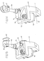
- la figure 8 illustre une section longitudinale selon l'axe I-I de la figure 6;
- la figure 9 illustre la pince fixe dans une vue en perspective;
- la figure 10 illustre une pince mobile faisant partie du groupe de tendage dans une coupe longitudinale;
- la figure 11 illustre dans une vue en perspective le groupe de formation du noeud en position de début de cycle de formation du noeud;
- la figure 12 illustre le groupe de formation du noeud en position de noeud formé mais maintenu;
- la figure 13 illustre le groupe de formation du noeud en position de noeud formé en condition de relâchement;
- les figures 14 et 15 illustrent dans une vue en perspective un détail du support de roulettes du groupe de formation du noeud dans deux positions de travail;
- la figure 16 illustre dans une vue en perspective un mécanisme de tablettes portant les roulettes sur lesquelles est enroulée la corde pendant la formation du noeud et avec la corde tendue pendant la formation du noeud;
- les figures 17 et 18 illustrent dans deux vues en perspective, du haut et du bas, un mécanisme de mise en mouvement de deux bras manipulateurs du groupe de formation du noeud;
- la figure 19 illustre un bras manipulateur pendant la formation du noeud.
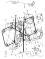
- Figure 1 illustrates the machine as a whole in a perspective view;
- FIG. 2 illustrates in a perspective view the tenderness group of the rope and the formation group of the knot in insertion position on the butt of the ham;
- Figure 3 illustrates in the same view as Figure 2 the tendon group and the formation group in position below the translational plane of the ham during the formation of the node;
- Figure 4 illustrates in a front view a fixed clamp of the tendon group;
- Figure 5 illustrates in a view from above the fixed clamp of Figure 4;
- Figures 6 and 7 illustrate the two side views of the fixed clamp of the tendon group;
- Figure 8 illustrates a longitudinal section along the axis II of Figure 6;
- Figure 9 illustrates the stationary clamp in a perspective view;
- Figure 10 illustrates a movable clamp forming part of the tendon group in a longitudinal section;
- FIG. 11 illustrates in a perspective view the formation group of the node in the starting position of the formation cycle of the node;
- Figure 12 illustrates the formation group of the knot node formed but maintained;
- Fig. 13 illustrates the formation group of the knot-node formed in looseness condition;
- Figures 14 and 15 illustrate in perspective view a detail of the caster support of the node forming group in two working positions;
- Figure 16 illustrates in a perspective view a tablet mechanism carrying the rollers on which is wound the rope during the formation of the knot and with the rope stretched during the formation of the knot;
- Figures 17 and 18 illustrate in two perspective views, from above and from below, a mechanism for setting in motion two manipulator arms of the node forming group;
- Figure 19 illustrates a manipulator arm during node formation.
En référence aux figures 1, 2 et 3, 1 indique le
châssis supportant toute la machine qui se compose d'un
plan supérieur 2 et d'un plan inférieur 3 sur lequel
repose une bobine de corde 4.
5 indique un premier convoyeur de jambons disposés sur
le convoyeur avec la crosse orientée vers l'avant selon
le sens du mouvement du convoyeur.With reference to FIGS. 1, 2 and 3, 1 indicates the
chassis supporting the entire machine which consists of a
Les jambons sont maintenus par des parois d'arrêt 6
disposées au-dessus du convoyeur.The hams are held by
Les parois d'arrêt 6 sont supportées par des bras 6a
qui peuvent pivoter pour les ouvrir et laisser passer à
cadence prédéterminée les jambons disposés
longitudinalement et avec la crosse en avant.The
Successivement au premier convoyeur 5 est prévu un
second convoyeur 7 sur lequel sont prévues des parois
d'arrêt 8 analogues aux précédentes.Successively at the
Espacé du second convoyeur, un troisième convoyeur 9
est prévu pour le déchargement des jambons auxquels a
été appliquée la corde de suspension.Spaced second conveyor, a
Transversalement à la machine, entre le second tapis
convoyeur 7 et le troisième tapis convoyeur 9, est
inséré un groupe de tendage 10 de la corde constitué
par une pince fixe 11 et une pince mobile 12, ainsi
qu'un groupe de formation du noeud indiqué dans son
ensemble par 13.Crosswise to the machine, between the
En référence aux figures 4 à 10 sera maintenant décrit
le groupe de tendage de la corde provenant de la bobine
4, qui est insérée entre une roue dentée 16 et une
courroie folle 17, la roue dentée 16 étant motorisée
par l'intermédiaire d'un moteur 18.With reference to Figures 4 to 10 will now be described
the tendon group of the rope coming from the reel
4, which is inserted between a
Avec 19 et 20 ont été indiqués deux rouleaux sur
lesquels s'enroule la courroie qui peut osciller autour
de l'axe du rouleau 20, de part la commande d'un piston
pneumatique 21. Comme cela est mieux visible dans les
figures 6 à 8, la pince fixe prévoit un canal 22 dans
lequel s'insère un excentrique denté 23 qui peut
interférer avec la corde.With 19 and 20 were indicated two rollers on
which wraps the strap that can swing around
of the axis of the
Successivement, le long du canal, est prévue une
roulette 14 actionnée par un actionneur 30 pour
l'avancée de la corde dans le canal 22.
31 indique un piston de pression de la roulette
d'alimentation 14 (figure 8) contre la corde.Successively, along the canal, is planned a
L'excentrique denté 23 est porté à interférer avec la
corde pour en effectuer le blocage par l'intermédiaire
de la poussée d'une bielle 24 entablée excentrique par
rapport au point de rotation de l'excentrique denté, la
bielle étant commandée par un vérin pneumatique de
blocage 25.
26 indique une lame à guillotine qui interfère avec le
canal 22 et est commandée par un piston de coupe 27.The toothed eccentric 23 is worn to interfere with the
rope to do the blocking through
of the thrust of an eccentric
Après la lame est prévu un orifice de sortie 28 au
travers duquel sort un morceau de corde 29 apte à être
pincé par la pince mobile 12.After the blade is provided an
En référence à la figure 10, la pince mobile 12 prévoit
un canal 33 pourvu d'une amorce 34, le long duquel peut
interférer un excentrique denté 35 qui bloque le
morceau de corde 29 par l'intermédiaire de
l'actionnement d'une bielle 36 et d'un piston de
blocage 37.With reference to FIG. 10, the
La pince mobile 12 est supportée par des guides de
coulissement pour être translatée par la tige d'un
vérin 12a.The
En référence aux figures 11, 12 et 13, l'on décrira le
groupe de formation du noeud disposé entre la pince
mobile et la pince fixe. Le groupe de formation du noeud
comprend deux bras manipulateurs 38 soutenus par des
tourelles 39 pivotant autour d'un axe vertical et
disposées en face de quatre tablettes 40, chacune
desquelles portant deux roulettes rainurées et folles
42.With reference to FIGS. 11, 12 and 13, the description will be
node forming group disposed between the clamp
mobile and the fixed clamp. The formation group of the node
includes two
Les tablettes 40 peuvent pivoter autour d'un axe
horizontal perpendiculaire au sens d'avancée des tapis
convoyeurs.
En position de début de cycle de formation du noeud,
lesdites roulettes 42 reposent toutes sur un plan
horizontal avec le propre axe de rotation verticale et
peuvent se porter dans une position pivotée de 90° avec
les axes de rotation parallèles au sens du mouvement
des tapis convoyeurs et, successivement, peuvent se
porter avec les axes parallèles à l'axe de tendage de
la corde transversal audit tapis convoyeur, selon les
séquences qui seront décrites ci-dessous.In the beginning position of the formation cycle of the node,
said
Les bras manipulateurs 38 sont constitués de deux tiges
38a et 38b, dont la 38b a une forme de crochet pour
saisir la corde et la porter à s'enrouler autour de
toutes les quatre roulettes folles 42.The
Dans l'angle d'union entre la tige 38a et la tige 38b,
est prévue une dent 38c (figure 19) apte à engager la
corde 41.In the angle of union between the
En référence aux figures 14 et 15, l'on note que les
roulettes 42 pour assumer les positions décrites ci-dessus
sont montées sur les tablettes de support 40
pivotant autour de l'axe 51 pour se porter de ladite
position d'enroulement à la position de la figure 12
dans laquelle le noeud est formé et maintenu.With reference to Figures 14 and 15, it is noted that the
Pour se porter dans la position de relâchement du noeud,
sur le support 50 est monté un actionneur pneumatique
52 qui, par l'intermédiaire de deux tiges 53 et 54,
entablées entre elles en 55, font pivoter de 90°
l'arbre 56 sur lequel sont emboítées, par
l'intermédiaire de deux mors 57, les deux roulettes
folles 42.To be in the position of loosening of the knot,
on the support 50 is mounted a
Les deux pinces fixes et mobiles et le groupe de formation du noeud sont respectivement supportés par des arbres 58, 59 et 60 qui peuvent translater verticalement pour porter le groupe de tendage et le groupe de formation du noeud dans le même temps au-dessous du plan de coulissement du second et du troisième tapis pendant toute la formation du noeud, ou au-dessus dudit plan durant l'insertion de la crosse dans le noeud formé avant la rotation des roulettes dans la position de décrochage du noeud.The two fixed and moving forceps and the group of node formation are respectively supported by trees 58, 59 and 60 that can translate vertically to carry the tenderness group and the knot formation group at the same time below of the sliding plan of the second and third carpet during the entire formation of the knot, or above said plane during insertion of the buttstock in the knot formed before the rotation of the wheels in the stall position of the node.
Pour effectuer le tendage de la corde une fois que la
crosse a été insérée dans le noeud et donc pour
effectuer la fermeture du noeud, sont prévues deux
barres 61 et 62 qui sont amenées à se trouver entre le
groupe de formation et les pinces.To tense the rope once the
butt was inserted into the knot and so for
perform the closure of the node, are provided two
Les barres sont montées sur des colonnes 63 qui, avant
l'abaissement desdits groupes, sont faites translater
vers le bas de manière à ce qu'elles s'appuient sur la
corde pour la tirer vers le bas.The bars are mounted on
En référence à la figure 16, l'on décrira maintenant le
mécanisme qui provoque le basculement dans le même
temps des quatre tablettes 40 portant chacune deux
roulettes folles 42 pour les porter de la position
illustrée dans les figures 11 et 16 à la position
illustrée dans la figure 12.Referring to Figure 16, the description will now be
mechanism that causes the switchover in the same
time of the four
Par 65 est indiqué un pignon qui s'engrène sur deux
crémaillères 64 parallèles, lesdites crémaillères
présentant une double file de dents entre elles
perpendiculaires de manière à ce que la file de dents
verticale s'engrène sur ledit pignon 65, alors que la
file de dents horizontale de chaque crémaillère
s'engrène sur deux secteurs dentés 66, chacun desquels
emboíté sur un arbre 67, avec un axe 51, sur lequel est
également emboítée la tablette 40.By 65 is indicated a gear which meshes with two
Le pignon 65 est motorisé par un actionneur situé au-dessous
et non illustré.The
En référence aux figures 17 et 18, l'on décrira
maintenant le mécanisme de mise en mouvement des deux
bras manipulateurs 38, chacun desquels étant supporté
par la tourelle 39.With reference to FIGS. 17 and 18, it will be described
now the mechanism of setting in motion the two
Le manipulateur 38 est encharné sur le bras vertical
d'une équerre 69 fixée à la tourelle 39 à l'intérieur
de laquelle peut coulisser un arbre rainuré 70 qui
porte sur son sommet, encharnées, deux bielles 68
encharnées sur l'autre extrémité sur le manipulateur.The
Sur l'arbre rainuré 70 est également insérée une poulie
71 reliée par une courroie 72 à une autre poulie 73
actionnée par un actionneur linéaire 74 qui se déplace
selon un mouvement de translation rectiligne
alternatif.On the
Sur l'arbre rainuré 70 est également emboítée une
poulie rainurée 75 dans laquelle s'engage une fourche
76 portée par un levier 77 entablé en 78.On the
Au bras moteur du levier 77 est encharnée la tige d'un
piston 79 dont le mouvement provoque la rotation du
levier 77 et le déplacement en vertical de l'arbre
rainuré qui intervient sur le basculement du
manipulateur par l'intermédiaire de la bielle 68.At the motor arm of the
Pour conclure, l'actionneur linéaire 74 provoque la
rotation alternée du manipulateur, alors que le piston
79 provoque le basculement de 90° du manipulateur pour
le porter de la position de repos illustrée par les
figures 17 et 18 à la position opérative illustrée dans
la figure 11.To conclude, the
Par 80, 81 et 82 sont indiqués enfin trois arbres qui
supportent respectivement la pince fixe, le groupe de
formation du noeud, et la pince mobile; lesdits arbres
peuvent translater verticalement dans le meme temps
pour se déplacer d'une position abaissée de formation
du noeud sous le plan de coulissement du jambon à une
position dans laquelle la crosse du jambon se trouve
substantiellement dans l'axe avec les deux anses du
noeud de type en demi-clef. Les mécanismes de
translation des arbres sont disposés sous le plan 2 et
ne sont pas illustrés puisque de type traditionnel.By 80, 81 and 82 are finally indicated three trees which
respectively support the fixed clamp, the group of
node formation, and the movable clamp; said trees
can translate vertically in the same time
to move from a lowered training position
of the knot under the sliding plane of the ham to a
position in which the stick of ham is
substantially in line with the two handles of the
type node in half-key. Mechanisms of
translation of the trees are arranged under
L'on décrira maintenant le fonctionnement de la machine.We will now describe the operation of the machine.
La machine étant privée de corde, au début du travail,
l'on effectue l'insertion du bout de la corde entre la
roue dentée 16 et la courroie folle 17 qui a été
éloignée de la roue dentée de part l'intervention du
piston 21.The machine being deprived of rope, at the beginning of the work,
the end of the rope is inserted between the
L'on fait avancer manuellement la corde dans le canal
22 jusqu'à la lame et l'on donne la commande de coupe
de la corde pour en ébarber le bout. La pince mobile 12
se porte en contact avec la pince fixe 11 avec le canal
33 coïncidant avec le canal 22.The rope is manually advanced in the
L'on effectue le rapprochement de ladite courroie à la roue dentée motorisée dans le sens contraire à l'avancement de la corde pour maintenir une certaine tension.The approximation of said belt to the motorized gear wheel in the opposite direction to the advancement of the rope to maintain some voltage.
L'intervention de la roue d'alimentation 14 motorisée
par l'actionneur 30 fait avancer la corde jusqu'à faire
sortir un morceau du canal 22 et l'introduire dans le
canal 33 de la pince mobile.The intervention of the
Ladite opération est facilitée du fait que la roue
d'alimentation est maintenue pressée contre la corde
par le piston 31.Said operation is facilitated by the fact that the wheel
feeding is kept pressed against the rope
by the
L'intervention du vérin 37 provoque l'accrochage de
l'excentrique denté 35 et le blocage de la corde située
au-dessous.The intervention of the
Au moyen de l'intervention du piston 12a, l'on provoque
le retour de la pince mobile 12 en position de départ
et donc le tendage de la corde 41 entre les deux pinces
perpendiculairement à la direction du mouvement du
jambon.By means of the intervention of the piston 12a, the
the return of the
Pendant cette phase, pour maintenir tendue la corde, l'on commande le vérin pneumatique pour rapprocher la courroie à la roue dentée motorisée et l'on active le relatif moteur qui pivote en sens contraire à celui d'enroulement de la corde.During this phase, to keep the rope taut, the pneumatic cylinder is controlled to bring the belt to the motorized gear wheel and activate the relative motor that pivots in the opposite direction to that winding the rope.
L'on trouve ensuite l'intervention en séquence des bras
manipulateurs 38 qui se portent d'une position de repos
verticale à une position de début de cycle horizontale
pour porter la corde à entourer en séquence les huit
roulettes de formation du noeud, tout en se maintenant
sur un plan horizontal.Then we find the intervention in sequence of the
Le basculement de 90° des deux couples de quatre roulettes provoque la formation du noeud qui est successivement translaté en vertical pour le porter en position d'enfilage de la crosse.The tilting of 90 ° of the two couples of four casters causes the formation of the knot that is successively translated in vertical to carry it in threading position of the butt.
La translation verticale du noeud se produit en actionnant les trois arbres qui soutiennent la pince mobile, la pince fixe et le groupe de formation du noeud.The vertical translation of the node occurs in actuating the three trees that support the clamp mobile, the fixed clamp and the training group of the node.
L'insertion de la crosse dans le noeud formé étant effectuée, les roulettes pivoteront encore de 90° pour se porter dans une position avec l'axe de rotation perpendiculaire au sens d'avancée du tapis, et elles pourront ainsi relâcher le noeud formé qui tombera sur la crosse du jambon.The insertion of the butt in the formed knot being performed, the castors will still rotate 90 ° to to move to a position with the axis of rotation perpendicular to the direction of advance of the carpet, and they will be able to release the formed node that will fall on the butt of the ham.
L'abaissement des barres 61 provoquera le tendage et le
serrage du noeud.Lowering the
Avant l'abaissement des barres 61, l'on obtiendra le
blocage de la corde dans la pince fixe.Before the lowering of the
Se produira alors l'ouverture de la pince mobile et
l'intervention du piston de coupe 27 pour la coupe de
la corde.Will then occur opening the movable clamp and
the intervention of the
Le second tapis convoyeur pourra s'activer pour porter le jambon sur le troisième tapis convoyeur de déchargement.The second conveyor belt can be activated to carry the ham on the third conveyor belt of unloading.
Tout le groupe de formation du noeud et les pinces
retournent en bas sous les tapis convoyeurs et les
roulettes 42 pivotent autour de leur axe de support et
basculent, de part la rotation des respectives
tablettes 40, en retournant dans un plan horizontal
avec axe de rotation vertical pour commencer le cycle
de formation d'un autre noeud.All the formation group of the knot and the pliers
go back down under the conveyor belts and the
La machine prévoit substantiellement de former le noeud sans la présence du jambon et d'effectuer l'insertion de la crosse dans le noeud préformé dans une phase successive, ceci permettant d'effectuer la procédure de nouage en automatique sans l'intervention d'un opérateur.The machine substantially plans to form the knot without the presence of ham and perform the insertion of the butt in the preformed node in a phase successively, this allows the procedure of automatic knotting without the intervention of a operator.
Claims (7)
Applications Claiming Priority (2)
| Application Number | Priority Date | Filing Date | Title |
|---|---|---|---|
| ITPR20030094 | 2003-10-20 | ||
| ITPR20030094 ITPR20030094A1 (en) | 2003-10-20 | 2003-10-20 | MACHINE TO KNOT A ROPE TO THE LEG OF A HAM. |
Publications (1)
| Publication Number | Publication Date |
|---|---|
| EP1525800A1 true EP1525800A1 (en) | 2005-04-27 |
Family
ID=34385832
Family Applications (1)
| Application Number | Title | Priority Date | Filing Date |
|---|---|---|---|
| EP04024831A Withdrawn EP1525800A1 (en) | 2003-10-20 | 2004-10-19 | Ham tying machine |
Country Status (2)
| Country | Link |
|---|---|
| EP (1) | EP1525800A1 (en) |
| IT (1) | ITPR20030094A1 (en) |
Cited By (1)
| Publication number | Priority date | Publication date | Assignee | Title |
|---|---|---|---|---|
| ITPR20090041A1 (en) * | 2009-05-15 | 2010-11-16 | Flii Ziveri S N C Di Ziveri Romano & C | MACHINE AND PROCEDURE FOR FEEDING HAMS TO A BINDER |
Citations (4)
| Publication number | Priority date | Publication date | Assignee | Title |
|---|---|---|---|---|
| US2358685A (en) * | 1941-12-05 | 1944-09-19 | Bunn Co B | Machine tying of hams and the like |
| FR2435910A1 (en) * | 1978-09-15 | 1980-04-11 | Pujol Yves | Machine to tie thread around neck of sausage etc. - encircles neck and leaves suspension loop extending from self locking knot |
| IT1235740B (en) * | 1989-09-29 | 1992-09-24 | Bu Ge Go S N C Di Buzzoni Mari | A Machine that automatically knots a string to the leg of prosciutto |
| DE29600705U1 (en) * | 1995-01-20 | 1996-03-28 | Spinnerei Und Seilerwarenfabri | Device for strapping food or the like. |
-
2003
- 2003-10-20 IT ITPR20030094 patent/ITPR20030094A1/en unknown
-
2004
- 2004-10-19 EP EP04024831A patent/EP1525800A1/en not_active Withdrawn
Patent Citations (4)
| Publication number | Priority date | Publication date | Assignee | Title |
|---|---|---|---|---|
| US2358685A (en) * | 1941-12-05 | 1944-09-19 | Bunn Co B | Machine tying of hams and the like |
| FR2435910A1 (en) * | 1978-09-15 | 1980-04-11 | Pujol Yves | Machine to tie thread around neck of sausage etc. - encircles neck and leaves suspension loop extending from self locking knot |
| IT1235740B (en) * | 1989-09-29 | 1992-09-24 | Bu Ge Go S N C Di Buzzoni Mari | A Machine that automatically knots a string to the leg of prosciutto |
| DE29600705U1 (en) * | 1995-01-20 | 1996-03-28 | Spinnerei Und Seilerwarenfabri | Device for strapping food or the like. |
Cited By (1)
| Publication number | Priority date | Publication date | Assignee | Title |
|---|---|---|---|---|
| ITPR20090041A1 (en) * | 2009-05-15 | 2010-11-16 | Flii Ziveri S N C Di Ziveri Romano & C | MACHINE AND PROCEDURE FOR FEEDING HAMS TO A BINDER |
Also Published As
| Publication number | Publication date |
|---|---|
| ITPR20030094A1 (en) | 2005-04-21 |
Similar Documents
| Publication | Publication Date | Title |
|---|---|---|
| EP0080422B1 (en) | Machine for automatically, cyclically tying filled or empty objects by means of a wire or string | |
| WO2006053909A1 (en) | Automatic machine for tying a knot using a string end of a tubular sleeve for sealing same by constriction when the knot is tightened | |
| FR2560803A1 (en) | IMPROVED STAPLING APPARATUS | |
| EP0015223B1 (en) | Machine for tying wire coils | |
| FR2494960A1 (en) | INSTALLATION FOR CUTTING MEAT | |
| FR2571213A1 (en) | PROCESS FOR PRODUCING PARALLELEPIPEDIC BALLS OF LARGE CUTTER HEATING DIMENSIONS AND PRESSING THEREFOR | |
| EP1525800A1 (en) | Ham tying machine | |
| EP0332532B1 (en) | Device for tying rods, bars or the like using a flexible metallic wire | |
| FR2541562A1 (en) | Automatic vine grafting method and machine for applying this method | |
| CH616829A5 (en) | automatic machine for making a clove hitch with a cord around an object and use of the machine | |
| FR2701452A1 (en) | Bale wrapper device | |
| EP2028946B1 (en) | Device for industrially trussing a fowl | |
| FR2483358A1 (en) | METHOD FOR FORMING A LINK ON A PACKAGING, DIE HEAD FOR CARRYING OUT SAID METHOD, AND MACHINE COMPRISING SUCH A HEAD | |
| FR2611650A1 (en) | DEVICE FOR TIETING A FLEXIBLE LINK | |
| EP1419697A1 (en) | Method and apparatus for trussing poultry | |
| FR2563183A1 (en) | Automatic machine permitting simultaneous tying, according to a preestablished cycle, of the two ends of a product defined from a continuous chain of several products to be tied and having alternate full zones and empty zones | |
| WO1993000727A1 (en) | Device for obtaining open loops on electric wire sections and for holding them during processing of their extremities | |
| FR2621010A1 (en) | Machine for sealing trays for packaging cooked dishes or other similar articles | |
| FR2753604A1 (en) | METHOD AND MACHINE FOR FISHING KILLED POULTRY | |
| CH370005A (en) | Stapling machine for bag closing | |
| EP0224421A1 (en) | Machine for automatically tying products such as sausages by means of a wire or string | |
| EP0092462A1 (en) | Production and transporting apparatus for processed pieces of wire | |
| CH496132A (en) | Method for automatically closing the end of a tubular fabric article and apparatus for carrying out this method | |
| EP0076741B1 (en) | Automatic binding process with a tie of which the ends are superposed in an opposed direction during binding, and device for carrying out this process | |
| CH529241A (en) | Yarn warper - including completely mechanised finish applicator and dryer |
Legal Events
| Date | Code | Title | Description |
|---|---|---|---|
| PUAI | Public reference made under article 153(3) epc to a published international application that has entered the european phase |
Free format text: ORIGINAL CODE: 0009012 |
|
| AK | Designated contracting states |
Kind code of ref document: A1 Designated state(s): AT BE BG CH CY CZ DE DK EE ES FI FR GB GR HU IE IT LI LU MC NL PL PT RO SE SI SK TR |
|
| AX | Request for extension of the european patent |
Extension state: AL HR LT LV MK |
|
| 17P | Request for examination filed |
Effective date: 20050802 |
|
| AKX | Designation fees paid |
Designated state(s): DE ES FR IT |
|
| GRAP | Despatch of communication of intention to grant a patent |
Free format text: ORIGINAL CODE: EPIDOSNIGR1 |
|
| STAA | Information on the status of an ep patent application or granted ep patent |
Free format text: STATUS: THE APPLICATION IS DEEMED TO BE WITHDRAWN |
|
| 18D | Application deemed to be withdrawn |
Effective date: 20060617 |