EP1524807B1 - Creating a low bandwidth channel within a high bandwidth packet stream - Google Patents
Creating a low bandwidth channel within a high bandwidth packet stream Download PDFInfo
- Publication number
- EP1524807B1 EP1524807B1 EP04255815A EP04255815A EP1524807B1 EP 1524807 B1 EP1524807 B1 EP 1524807B1 EP 04255815 A EP04255815 A EP 04255815A EP 04255815 A EP04255815 A EP 04255815A EP 1524807 B1 EP1524807 B1 EP 1524807B1
- Authority
- EP
- European Patent Office
- Prior art keywords
- packet
- output
- extra
- memory
- bandwidth
- Prior art date
- Legal status (The legal status is an assumption and is not a legal conclusion. Google has not performed a legal analysis and makes no representation as to the accuracy of the status listed.)
- Expired - Lifetime
Links
- 238000000034 method Methods 0.000 claims description 12
- 230000005540 biological transmission Effects 0.000 claims description 7
- 230000003287 optical effect Effects 0.000 claims description 4
- 238000006243 chemical reaction Methods 0.000 claims 3
- 230000007704 transition Effects 0.000 description 13
- 239000000872 buffer Substances 0.000 description 11
- 230000000694 effects Effects 0.000 description 9
- 238000003780 insertion Methods 0.000 description 8
- 230000037431 insertion Effects 0.000 description 8
- 238000004891 communication Methods 0.000 description 6
- 230000006870 function Effects 0.000 description 5
- 230000003111 delayed effect Effects 0.000 description 4
- 238000010586 diagram Methods 0.000 description 4
- 230000001934 delay Effects 0.000 description 2
- 238000005259 measurement Methods 0.000 description 2
- 238000012544 monitoring process Methods 0.000 description 2
- 238000012545 processing Methods 0.000 description 2
- UPLPHRJJTCUQAY-WIRWPRASSA-N 2,3-thioepoxy madol Chemical compound C([C@@H]1CC2)[C@@H]3S[C@@H]3C[C@]1(C)[C@@H]1[C@@H]2[C@@H]2CC[C@](C)(O)[C@@]2(C)CC1 UPLPHRJJTCUQAY-WIRWPRASSA-N 0.000 description 1
- 238000010521 absorption reaction Methods 0.000 description 1
- 230000002411 adverse Effects 0.000 description 1
- 230000009172 bursting Effects 0.000 description 1
Images


Classifications
-
- H—ELECTRICITY
- H04—ELECTRIC COMMUNICATION TECHNIQUE
- H04L—TRANSMISSION OF DIGITAL INFORMATION, e.g. TELEGRAPHIC COMMUNICATION
- H04L47/00—Traffic control in data switching networks
- H04L47/10—Flow control; Congestion control
-
- H—ELECTRICITY
- H04—ELECTRIC COMMUNICATION TECHNIQUE
- H04L—TRANSMISSION OF DIGITAL INFORMATION, e.g. TELEGRAPHIC COMMUNICATION
- H04L47/00—Traffic control in data switching networks
- H04L47/10—Flow control; Congestion control
- H04L47/13—Flow control; Congestion control in a LAN segment, e.g. ring or bus
-
- H—ELECTRICITY
- H04—ELECTRIC COMMUNICATION TECHNIQUE
- H04L—TRANSMISSION OF DIGITAL INFORMATION, e.g. TELEGRAPHIC COMMUNICATION
- H04L47/00—Traffic control in data switching networks
- H04L47/10—Flow control; Congestion control
- H04L47/28—Flow control; Congestion control in relation to timing considerations
-
- H—ELECTRICITY
- H04—ELECTRIC COMMUNICATION TECHNIQUE
- H04L—TRANSMISSION OF DIGITAL INFORMATION, e.g. TELEGRAPHIC COMMUNICATION
- H04L49/00—Packet switching elements
- H04L49/90—Buffering arrangements
-
- H—ELECTRICITY
- H04—ELECTRIC COMMUNICATION TECHNIQUE
- H04L—TRANSMISSION OF DIGITAL INFORMATION, e.g. TELEGRAPHIC COMMUNICATION
- H04L49/00—Packet switching elements
- H04L49/90—Buffering arrangements
- H04L49/901—Buffering arrangements using storage descriptor, e.g. read or write pointers
Definitions
- the present invention pertains to the art of packet-switched digital networks, in the preferred embodiments to injecting a low-bandwidth undirectional data stream into a high-bandwidth channel.
- channels for management, monitoring, and/or measurement functions In these functions, it is common to have a device connected to a high-bandwidth channel. The device performs some function, producing a low-bandwidth data stream as a result. Handling that low-bandwidth data stream requires that the device be connected to another communications channel, such as a wireless link, or a port on a high-speed switch.
- additional resources are dedicated to providing communications capability to these functions.
- WO 01/56195 discloses a digital status channel for a broadband communication system.
- the present invention seeks to provide an improved channel operation.
- a low-bandwidth channel is created in a high-bandwidth channel such that extra bandwidth is only used for the low-bandwidth channel when there is data to be sent, minimal latency is introduced in the high-bandwidth channel when there is no packet to be sent over the low-bandwidth channel, and the effects of sending a packet on the low-bandwidth channel are absorbed and distributed amongst other passing traffic.
- the preferred embodiment creates a low bandwidth channel by inserting packets into the high bandwidth packet stream.
- a low-bandwidth channel is created within the high-bandwidth channel by inserting packets at a predetermined interval. This insertion introduces latency into the high-bandwidth channel. This latency is not constant, but is recovered by minimizing inter-packet gaps between packets in the incoming high-bandwidth channel following the inserted packet. While the inserted packet is being transmitted, forming the low-bandwidth channel, arriving high-bandwidth packets are stored in an elastic buffer.
- Ethernet network studies have demonstrated that Ethernet networks work well if the bandwidth is utilized at no more than 30% of capacity. Heavier usage may cause collisions that lead to congestion. Retransmission may create more traffic and more collisions to the point that there will be very little traffic that makes it through. For backbone networks or inter-domain links, where there are fewer transmission originators, the traffic is much smoother, and the utilization of such links may reach 60-70% of capacity. There are fewer collisions because there are fewer parties competing at the switches where the traffic converges. Higher utilization and occasional traffic bursting may lead to substantial packets loss at the routers. While maximum packet size for basic Ethernet is 1536 bytes, typical traffic consists of a range of packet sizes.
- the described embodiment defines the upper bandwidth of the low bandwidth channel by specifying a hold timer.
- the hold timer defines an interval during which only one packet may be sent. When the hold timer expires, another packet may be sent over the low bandwidth channel. This may only occur under the condition where the high bandwidth packet stream absorbed any previous packet that was inserted. In other words the high bandwidth packet stream must return to moving unaltered before an extra packet may be inserted into the stream. Of course, the extra packet insertion would cause small, temporary delays in the high bandwidth packet stream.
- the hold timer is approximately 150,000 clock cycles.
- the clock cycle per byte for 1Gbps and with 8B/10B encoding of the bit stream is 10 nsec. This means, in this example, that no other packet could be introduced to the high bandwidth packet stream in less than 1.5 msec. Smaller packet sizes will have smaller hold timer values and could be introduced more often. However, choosing smaller packets may increase the number of packets per second which may affect the router's processing capability if it is near its packet-per-second limit.
- the hold timer could have a random factor built in.
- the above calculated hold timer could be an average value that randomly fluctuates between a lower and upper bound.
- the hold timer could be within +-20% of an average. Randomization of the hold timer may prevent synchronization of traffic flow when the same size packets are inserted into the traffic. It is not proven that randomization of this hold timer may affect flow synchronization but various studies of traffic flows have shown that synchronization in general may have an adverse effect on the overall stability of the networks.
- inter-packet gap This is a gap between two consecutive packets or frames (e.g., Ethernet frames).
- the minimum inter-packet gap must be 96 nsec.
- the only way to reduce the impact of insertion of an extra packet (actually a packet that is framed) into the high bandwidth stream is by reducing inter-packet gaps of following packets that are greater than the minimum.
- the minimum gap could be defined as larger than a minimum gap defined by a specific standard. This may be necessary if the line card has problems handling minimum gaps defined by the standard.
- the minimum gap could also have a random factor built in to avoid possible harmful traffic synchronization. But a study has to be conducted to determine if that is necessary.
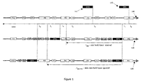
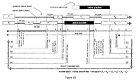
- Figure 1 illustrates how extra packets (frames) 110 and 112 are inserted into a high bandwidth packet stream 100. It should be repeated here that a "packet" is not just an IP packet but it is a frame that may contain an IP packet. In the case of Ethernet, it is an actual Ethernet frame that is already encoded e.g., using 8B/10B encoding. The type of encoding will depend on what type of encoding is used by passing traffic. In Figure 1, unaffected packets are shown in clear, delayed packets in gray, and inserted extra packets in black.
- the P1 packet will enter the elastic buffer, as well as the minimum gap between P1 and P2 when the extra packet is in the process of being sent. Also, the gap between P2 and P3 will be reduced so that the P3 packet will move without delay. Only P1 and P2 are affected (delayed) by the insertion of the EP1 packet but P3 is not delayed.
- the embodiment also starts a hold timer as defined earlier, shown as packet stream 120. Packet stream 130 illustrates a situation when a random factor is added to the hold timer.
- t 2 another extra packet EP2 112 is ready to be sent. However, at this time, we have not yet met the low bandwidth channel criteria and must wait until t 3, when the hold timer expires.
- a first embodiment of the present invention is shown in Figures 2 through 5; it introduces zero delay.
- a second embodiment of the present invention is shown in Figures 6 through 8 and uses a two-character delay.
- a third embodiment of the present invention is shown in Figures 9 through 11 and uses an arbitrary delay.
- the present invention is also suitable for implementation in a highly integrated form suitable for replacing industry-standard interface converter modules, for example those known as GBICs, or GigaBit Interface Converters.
- Current GBICs are basically transceivers translating one media type (optical, twisted pair, etc.) to another media type.
- GBICs are basically transceivers translating one media type (optical, twisted pair, etc.) to another media type.
- applications requiring low-bandwidth channels are enabled. Such applications include many network monitoring applications.
- the two-character delay shown in Figures 6 through 8 introduces a minimum, two characters delay for normal operation (i.e., traffic passing by is delayed by two characters). As shown in Figure 6, the extra packet is copied into FIFO buffer 650 before transmission.
- serial bit stream is de-serialized into parallel n-bit words, the result can only be forwarded for further processing (even just to re-serialize) after all n bits arrived.
- de-serializing and then re-serializing a bit stream introduces a latency of at least one word cycle or n bits.
- the serializer and the deserializer each can be expected to have more than one bit times of internal latency, for a total of about two word cycles (20ns for the Gigabit Ethernet example), even in the case of what we call the "zero-delay" solution.
- the invention must read and write to on-chip memory and detect idle characters at the word rate, e.g.
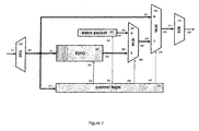
- Figures 2 through 5 show a zero delay (latency) embodiment of the current invention.
- the incoming stream of packets comes in on interface 211. Because it is a serial stream of bits (for 1 Gigabit Ethernet, it runs an actual line rate of 1.25 Gbps) it is de-serialized by de-serializer 210 into parallel streams of bits. If 8B/10B encoding is used (e.g., 1 Gigabit/sec Ethernet) the stream will be de-serialized into a 10 parallel bit stream 212. That stream will go three different routes, depending the system state.
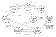
- De-serialization is a well-known technique to process high-speed data at lower speeds. For example in 1 Gigabit Ethernet data can be processed at 125 MHz instead of 1.25 GHz. If there is no other packet being sent or FIFO buffer 250 is empty (i.e., there is no effect of previously inserted packets on the main packet stream) the state of the control logic 230 is in the initial state - S0 of Figure 4.
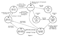
- the state machine described in Figure 4 shows how control logic 230 transitions from one state to another based on events.
- Figure 5 shows an example of a state transition.
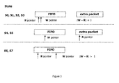
- Figure 2 illustrates the basic building blocks and Figure 3 describes how FIFO buffer pointers transition.
- any elastic buffer may be used.
- Hardware implementations may not require direct control of read and write pointers, for example, and single-port buffers may be used.
- the incoming packet stream data uses the "fast path". It moves from interface 212 to multiplexor MUX 270 through 271 interface.
- MUX 270 is in state 0 which allows the incoming data 271 to be forwarded through interface 273 and 221 to SERializer 220 which converts the parallel streams back into one serial stream 222 at the end.
- the output of SERializer 220 typically connects to outside network equipment, and may present an electrical or optical interface.
- Control logic 230 is in state S0.
- the hold time expires ( Figure 5) and control logic 230 moves from S0 to S1 state (event: hold timer expired; Figure 4,5).
- an extra packet ( Figure 5) is ready to be injected (event: extra packet ready ) into the stream.
- the state machine of control logic 230 switches to state S3 ( Figure 4 & 5).
- the control logic 230 starts sensing when to inject the extra packet. The sensing is done by checking each individual character 231 passing through control logic 230.
- the data can take 3 different paths after deserializer 212 of Figure 2..
- the first path was described above as the fast path.
- the second path 251 goes into FIFO buffer 250.
- the third path 231 enters control logic 230.
- Control logic 230 senses IDLE characters indicating the possibility of injecting the extra packet.
- the incoming packet data is also forwarded 251 to FIFO 250 but is not forwarded through MUX 280 because the state of MUX 280 is 0 and interface 282 only allows forwarding data if the state of MUX 280 is 1. Because the R pointer points to the extra packet the W (write) pointer will not advance at this time. The data will be written into FIFO 250 to the same location but reading will occur from the extra packet buffer.
- control logic 230 would change state S0 -> S2 -> S3 if event: extra packet ready occurs before event: hold timer expired ( Figure 4). Once those two events occur, control logic 230 will switch to state S4 .
- control logic 230 Once control logic 230 enters state S4 , it sends a signal through interface 232-274 to change MUX 270 state to 1 and signal 236-284 to set MUX 280 to state 0. At the same time, through signal 235-262 it starts a process of sending the extra packet 260 character by character. At t 3, the R pointer is pointing to the extra packet data. Extra packet characters will move through interface 261-281 to MUX 280 and then they will be forwarded through interface 283-272 to MUX 270. Because MUX 270 is in state 1, data goes through interface 273-221 to SERializer 220 and leaves thorough interface 222. At t 4 packet P1 arrives. An event: START frame will be generated and control logic 230 will transition to state S5 .
- FIFO 250 starts accumulating P1 characters, i.e. its W pointer starts advancing. This means also that a gap t 3 -t 4 was eliminated from the stream of packets to compensate for the effect of the extra packet insertion on the incoming packet stream delay. In the example shown in Figure 5, this gap (t 3 -t 4 ) is not sufficient to completely absorb the effect of the newly inserted extra packet and more inter-packet gaps must be used to compensate the effect.
- the extra packet must be trailed by at least the minimum gap.
- the gap between packets P0 and P1 is too small to accommodate the trailing gap for the inserted extra packet and therefore a minimum gap has to be included as part of the extra packet.
- the absorption of the effect of the insertion of extra packet (t 3 -t 4 ) is done simply by FIFO 250 not advancing its own W pointer.
- Control logic 230 switches through 236-284 interface MUX 280 to state 1 and sets R pointer to the beginning of FIFO 250 ( Figure 3, State S6, S7).
- data is being sent from FIFO 250.
- the FIFO's R pointer is set to a first character and this will be the first character of packet P1 saved in FIFO.
- FIFO 250 is accepting 251 and storing packet P2.
- minimum gap trailing packet P2 is reached.
- the last character from FIFO 250 is sent. It should be noted this is not the actual last character saved in the FIFO.
- the last character means a character that could be read from FIFO.
- the R pointer is, at this time, two characters behind the W pointer. Because we were receiving IDLE characters after the minimum gap was reached, the W pointer has not been advancing. In other words, IDLE characters between t 8 and t 9 were intentionally dropped from the incoming packet stream. If at t 9, the last two received characters were representing IDLE then, in the next clock cycle (next character) it will be safe to switch to the fast path. The only thing, which could be lost from the incoming packet stream, is this IDLE (i.e., two characters representing one IDLE).
- packet P3 arrives after t 9 .
- the last received character was the start frame character of packet P3
- This is a very crucial element of the invention. Switching from FIFO path to fast path can only occur when two characters representing an IDLE that were received but not yet sent can be dropped. And the only characters that can be dropped are IDLEs (two characters each), assuming of course, that the minimum gap was already sent.
- the FIFO path is always at least two characters behind the fast path, i.e., R pointer follows W pointer by no less than two characters.
- FIG. 6 A embodiment of the present invention using a two-character delay (size of an IDLE) is shown in figures 6 through 8.
- this embodiment uses register 640 in the path whose output 642 is fed either to FIFO 650 or leaves the logic through MUX 680 and SERializer 620.
- the difference between this embodiment and the zero-delay embodiment is twofold.
- register 640 introduces a permanent two-character delay and the extra packet is not injected into the packet stream from a separate memory but instead is copied to FIFO 650 first. This may simplify implementation of the memory controller and management of FIFO 650.
- Figures 6 through 8 illustrate the block diagram, suitable state machine, and example state transitions for this embodiment.
- Arbitrary delay solution An embodiment of the present invention using an arbitrary delay solution is a simplified version of zero delay without an option of zero delay.
- Figures 9 through 11 illustrate this embodiment, which is applicable for applications that require delays. For example, manipulation of IP headers or when entire packet will require withhold before releasing and modifying information in the packet header. It is, in concept, similar to store and forward techniques used by packet switches. Both the extra packet 240 and the packet stream 211 are stored in FIFO 250 and selectively routed to SERializer220 under control of a state machine according to Figure 11.
Landscapes
- Engineering & Computer Science (AREA)
- Computer Networks & Wireless Communication (AREA)
- Signal Processing (AREA)
- Data Exchanges In Wide-Area Networks (AREA)
- Communication Control (AREA)
Applications Claiming Priority (2)
| Application Number | Priority Date | Filing Date | Title |
|---|---|---|---|
| US688340 | 2003-10-17 | ||
| US10/688,340 US7336673B2 (en) | 2003-10-17 | 2003-10-17 | Creating a low bandwidth channel within a high bandwidth packet stream |
Publications (2)
| Publication Number | Publication Date |
|---|---|
| EP1524807A1 EP1524807A1 (en) | 2005-04-20 |
| EP1524807B1 true EP1524807B1 (en) | 2007-05-23 |
Family
ID=34377673
Family Applications (1)
| Application Number | Title | Priority Date | Filing Date |
|---|---|---|---|
| EP04255815A Expired - Lifetime EP1524807B1 (en) | 2003-10-17 | 2004-09-23 | Creating a low bandwidth channel within a high bandwidth packet stream |
Country Status (4)
| Country | Link |
|---|---|
| US (2) | US7336673B2 (enExample) |
| EP (1) | EP1524807B1 (enExample) |
| JP (1) | JP4709526B2 (enExample) |
| DE (1) | DE602004006573T2 (enExample) |
Families Citing this family (24)
| Publication number | Priority date | Publication date | Assignee | Title |
|---|---|---|---|---|
| US7848318B2 (en) | 2005-08-03 | 2010-12-07 | Altera Corporation | Serializer circuitry for high-speed serial data transmitters on programmable logic device integrated circuits |
| US20070076610A1 (en) * | 2005-09-30 | 2007-04-05 | Yang Liuyang L | Techniques using channel utilization metrics to avoid network under utilization for mesh flow control |
| US7764614B2 (en) * | 2005-11-15 | 2010-07-27 | Lsi Corporation | Multi-mode management of a serial communication link |
| US7746949B2 (en) | 2006-03-31 | 2010-06-29 | Jds Uniphase Corporation | Communications apparatus, system and method of creating a sub-channel |
| US8009557B2 (en) | 2006-04-27 | 2011-08-30 | Jds Uniphase Corporation | Communications system, apparatus for creating a sub-channel and method therefor |
| US20070253331A1 (en) * | 2006-04-27 | 2007-11-01 | Ilnicki Slawomir K | Communications system, apparatus and method of communicating sub-channel data |
| US8194662B2 (en) * | 2006-06-08 | 2012-06-05 | Ilnickl Slawomir K | Inspection of data |
| US20080232269A1 (en) | 2007-03-23 | 2008-09-25 | Tatman Lance A | Data collection system and method for ip networks |
| GB2449852A (en) * | 2007-06-04 | 2008-12-10 | Agilent Technologies Inc | Monitoring network attacks using pattern matching |
| US8131927B2 (en) * | 2007-11-30 | 2012-03-06 | Hitachi, Ltd. | Fast accessible compressed thin provisioning volume |
| EP2387180B1 (en) | 2010-05-14 | 2019-12-18 | Viavi Solutions Inc. | Network communication with unaddressed network devices |
| US8705395B2 (en) | 2010-06-15 | 2014-04-22 | Jds Uniphase Corporation | Method for time aware inline remote mirroring |
| US9397895B2 (en) | 2011-12-13 | 2016-07-19 | Viavi Solutions Inc. | Method and system for collecting topology information |
| US9106353B2 (en) | 2011-12-13 | 2015-08-11 | Jds Uniphase Corporation | Time synchronization for network testing equipment |
| US9570124B2 (en) | 2012-01-11 | 2017-02-14 | Viavi Solutions Inc. | High speed logging system |
| US9141506B2 (en) | 2012-02-15 | 2015-09-22 | Jds Uniphase Corporation | Method and system for network monitoring using signature packets |
| US9525750B2 (en) | 2013-02-13 | 2016-12-20 | Viavi Solutions Inc. | Method of collecting information about test devices in a network |
| US9313116B2 (en) | 2013-02-13 | 2016-04-12 | ViaviSolutions Inc. | Enhanced retry method |
| US9948565B2 (en) | 2013-08-19 | 2018-04-17 | Instart Logic, Inc. | Method and implementation of zero overhead rate controlled (ZORC) information transmission via digital communication link |
| US9769051B2 (en) | 2014-01-13 | 2017-09-19 | Viavi Solutions Inc. | Demarcation unit enclosure and method |
| US10630553B2 (en) | 2015-08-18 | 2020-04-21 | Walmart Apollo, Llc | Bandwidth throttling |
| CA3001335C (en) | 2015-10-16 | 2025-05-13 | Walmart Apollo Llc | SENSOR AND ALARM DATA ANALYSIS MANAGEMENT |
| CA2954037A1 (en) | 2016-01-21 | 2017-07-21 | Wal-Mart Stores, Inc. | Codeless information service for abstract retrieval of disparate data |
| US10732974B2 (en) | 2016-05-05 | 2020-08-04 | Walmart Apollo, Llc | Engine agnostic event monitoring and predicting systems and methods |
Family Cites Families (15)
| Publication number | Priority date | Publication date | Assignee | Title |
|---|---|---|---|---|
| JPS62104331A (ja) * | 1985-10-31 | 1987-05-14 | Nec Corp | デ−タ伝送方式 |
| JPH03104453A (ja) * | 1989-09-19 | 1991-05-01 | Fujitsu Ltd | 回線インタフェース装置 |
| JP3134818B2 (ja) * | 1997-07-31 | 2001-02-13 | 日本電気株式会社 | パケット多重化装置、パケット多重化方法、及びパケット多重化装置の制御プログラムを記録した媒体 |
| US6377998B2 (en) * | 1997-08-22 | 2002-04-23 | Nortel Networks Limited | Method and apparatus for performing frame processing for a network |
| JP2975932B1 (ja) * | 1998-07-09 | 1999-11-10 | 日本放送協会 | デジタル信号受信装置 |
| JP3970461B2 (ja) * | 1999-02-15 | 2007-09-05 | Necエンジニアリング株式会社 | 電話会議装置 |
| WO2001056195A2 (en) | 2000-01-26 | 2001-08-02 | Scientific-Atlanta, Inc. | Digital status channel for broadband communication system |
| US7089485B2 (en) * | 2000-02-03 | 2006-08-08 | Agere Systems Inc. | Simple link protocol providing low overhead coding for LAN serial and WDM solutions |
| US6741566B1 (en) | 2000-05-08 | 2004-05-25 | Metrobility Optical Systems, Inc. | Remote management ethernet network and device |
| GB2373671B (en) | 2001-03-23 | 2004-04-07 | Vodafone Ltd | Telecommunications systems and methods |
| US7046696B2 (en) | 2001-09-21 | 2006-05-16 | International Business Machines Corporation | Multiplexing high priority, low bandwidth information on a traditional link protocol |
| JP2003244180A (ja) * | 2002-02-21 | 2003-08-29 | Denso Corp | データ中継装置および多重通信システム |
| US7127648B2 (en) * | 2002-08-07 | 2006-10-24 | Broadcom Corporation | System and method for performing on-chip self-testing |
| US7111208B2 (en) * | 2002-10-02 | 2006-09-19 | Broadcom Corporation | On-chip standalone self-test system and method |
| US7463651B2 (en) * | 2003-02-12 | 2008-12-09 | Broadcom Corporation | Method and system for exploiting spare link bandwidth in a multilane communication channel |
-
2003
- 2003-10-17 US US10/688,340 patent/US7336673B2/en not_active Expired - Fee Related
-
2004
- 2004-09-23 EP EP04255815A patent/EP1524807B1/en not_active Expired - Lifetime
- 2004-09-23 DE DE602004006573T patent/DE602004006573T2/de not_active Expired - Lifetime
- 2004-10-15 JP JP2004301119A patent/JP4709526B2/ja not_active Expired - Fee Related
-
2007
- 2007-12-20 US US11/962,030 patent/US7948974B2/en not_active Expired - Lifetime
Non-Patent Citations (1)
| Title |
|---|
| None * |
Also Published As
| Publication number | Publication date |
|---|---|
| JP4709526B2 (ja) | 2011-06-22 |
| US7336673B2 (en) | 2008-02-26 |
| DE602004006573T2 (de) | 2008-01-31 |
| US7948974B2 (en) | 2011-05-24 |
| US20050083957A1 (en) | 2005-04-21 |
| DE602004006573D1 (de) | 2007-07-05 |
| JP2005124210A (ja) | 2005-05-12 |
| EP1524807A1 (en) | 2005-04-20 |
| US20080247410A1 (en) | 2008-10-09 |
Similar Documents
| Publication | Publication Date | Title |
|---|---|---|
| US7948974B2 (en) | Creating a low bandwidth channel within a high bandwidth packet stream | |
| US8819265B2 (en) | Managing flow control buffer | |
| US7009978B2 (en) | Communications interface for providing a plurality of communication channels to a single port on a processor | |
| US9030937B2 (en) | Backplane interface adapter with error control and redundant fabric | |
| CN101465805B (zh) | 集合的客户端分组的传输 | |
| US7564785B2 (en) | Dynamic flow control support | |
| US20050138238A1 (en) | Flow control interface | |
| US6992980B2 (en) | System and method for enabling a full flow control down to the sub-ports of a switch fabric | |
| JP2804988B2 (ja) | 不活性および活性情報ユニットの到着ストリームとともに用いられる平滑化装置、パケット間ギャップ長を制御するための方法、ならびに情報ユニットを搬送するためのネットワーク | |
| US7415031B2 (en) | Data link/physical layer packet diversion and insertion | |
| US20090300296A1 (en) | Communication apparatus with data discard functions and control method therefor | |
| US7272675B1 (en) | First-in-first-out (FIFO) memory for buffering packet fragments through use of read and write pointers incremented by a unit access and a fraction of the unit access | |
| CA2371037C (en) | A node and method for the removal of expired packets from a communication network | |
| CN101110661A (zh) | 电路仿真系统的抖动缓存调整方法 | |
| US7379467B1 (en) | Scheduling store-forwarding of back-to-back multi-channel packet fragments | |
| US8194691B2 (en) | Data link/physical layer packet buffering and flushing | |
| US20130329558A1 (en) | Physical layer burst absorption | |
| JP2009206696A (ja) | 伝送システム | |
| JP4652314B2 (ja) | イーサoamスイッチ装置 | |
| CN116708871A (zh) | 一种基于tsn视频业务传输方法、设备及介质 | |
| JP4321164B2 (ja) | データ伝送装置及びそれに用いるデータ伝送方法 | |
| EP1052807A1 (en) | Communications network using priority classes | |
| EP1897287A1 (en) | A method for buffering data | |
| JP2011023777A (ja) | フレーム伝送帯域制御システム及びフレーム伝送帯域制御方法 |
Legal Events
| Date | Code | Title | Description |
|---|---|---|---|
| PUAI | Public reference made under article 153(3) epc to a published international application that has entered the european phase |
Free format text: ORIGINAL CODE: 0009012 |
|
| AK | Designated contracting states |
Kind code of ref document: A1 Designated state(s): AT BE BG CH CY CZ DE DK EE ES FI FR GB GR HU IE IT LI LU MC NL PL PT RO SE SI SK TR |
|
| AX | Request for extension of the european patent |
Extension state: AL HR LT LV MK |
|
| 17P | Request for examination filed |
Effective date: 20050711 |
|
| RAP1 | Party data changed (applicant data changed or rights of an application transferred) |
Owner name: AGILENT TECHNOLOGIES, INC. |
|
| AKX | Designation fees paid |
Designated state(s): DE FR GB |
|
| GRAP | Despatch of communication of intention to grant a patent |
Free format text: ORIGINAL CODE: EPIDOSNIGR1 |
|
| RAP1 | Party data changed (applicant data changed or rights of an application transferred) |
Owner name: AGILENT TECHNOLOGIES, INC. |
|
| GRAS | Grant fee paid |
Free format text: ORIGINAL CODE: EPIDOSNIGR3 |
|
| GRAA | (expected) grant |
Free format text: ORIGINAL CODE: 0009210 |
|
| AK | Designated contracting states |
Kind code of ref document: B1 Designated state(s): DE FR GB |
|
| REG | Reference to a national code |
Ref country code: GB Ref legal event code: FG4D |
|
| REF | Corresponds to: |
Ref document number: 602004006573 Country of ref document: DE Date of ref document: 20070705 Kind code of ref document: P |
|
| ET | Fr: translation filed | ||
| PLBE | No opposition filed within time limit |
Free format text: ORIGINAL CODE: 0009261 |
|
| STAA | Information on the status of an ep patent application or granted ep patent |
Free format text: STATUS: NO OPPOSITION FILED WITHIN TIME LIMIT |
|
| 26N | No opposition filed |
Effective date: 20080226 |
|
| PGFP | Annual fee paid to national office [announced via postgrant information from national office to epo] |
Ref country code: FR Payment date: 20070917 Year of fee payment: 4 |
|
| REG | Reference to a national code |
Ref country code: FR Ref legal event code: ST Effective date: 20090529 |
|
| PG25 | Lapsed in a contracting state [announced via postgrant information from national office to epo] |
Ref country code: FR Free format text: LAPSE BECAUSE OF NON-PAYMENT OF DUE FEES Effective date: 20080930 |
|
| REG | Reference to a national code |
Ref country code: DE Ref legal event code: R082 Ref document number: 602004006573 Country of ref document: DE Representative=s name: SCHOPPE, ZIMMERMANN, STOECKELER, ZINKLER & PAR, DE |
|
| REG | Reference to a national code |
Ref country code: GB Ref legal event code: 732E Free format text: REGISTERED BETWEEN 20130530 AND 20130605 |
|
| REG | Reference to a national code |
Ref country code: DE Ref legal event code: R081 Ref document number: 602004006573 Country of ref document: DE Owner name: JDS UNIPHASE CORP., US Free format text: FORMER OWNER: AGILENT TECHNOLOGIES, INC. (N.D.GES.D. STAATES DELAWARE), SANTA CLARA, US Effective date: 20130528 Ref country code: DE Ref legal event code: R082 Ref document number: 602004006573 Country of ref document: DE Representative=s name: SCHOPPE, ZIMMERMANN, STOECKELER, ZINKLER & PAR, DE Effective date: 20130528 Ref country code: DE Ref legal event code: R081 Ref document number: 602004006573 Country of ref document: DE Owner name: JDS UNIPHASE CORP., MILPITAS, US Free format text: FORMER OWNER: AGILENT TECHNOLOGIES, INC. (N.D.GES.D. STAATES DELAWARE), SANTA CLARA, CALIF., US Effective date: 20130528 Ref country code: DE Ref legal event code: R082 Ref document number: 602004006573 Country of ref document: DE Representative=s name: SCHOPPE, ZIMMERMANN, STOECKELER, ZINKLER, SCHE, DE Effective date: 20130528 Ref country code: DE Ref legal event code: R082 Ref document number: 602004006573 Country of ref document: DE Representative=s name: MURGITROYD & COMPANY, DE Effective date: 20130528 Ref country code: DE Ref legal event code: R081 Ref document number: 602004006573 Country of ref document: DE Owner name: VIAVI SOLUTIONS INC. (N. D. GES. D. STAATES DE, US Free format text: FORMER OWNER: AGILENT TECHNOLOGIES, INC. (N.D.GES.D. STAATES DELAWARE), SANTA CLARA, CALIF., US Effective date: 20130528 |
|
| REG | Reference to a national code |
Ref country code: DE Ref legal event code: R082 Ref document number: 602004006573 Country of ref document: DE Representative=s name: MURGITROYD & COMPANY, DE |
|
| REG | Reference to a national code |
Ref country code: DE Ref legal event code: R082 Ref document number: 602004006573 Country of ref document: DE Representative=s name: MURGITROYD & COMPANY, DE Ref country code: DE Ref legal event code: R081 Ref document number: 602004006573 Country of ref document: DE Owner name: VIAVI SOLUTIONS INC. (N. D. GES. D. STAATES DE, US Free format text: FORMER OWNER: JDS UNIPHASE CORP., MILPITAS, CALIF., US |
|
| PGFP | Annual fee paid to national office [announced via postgrant information from national office to epo] |
Ref country code: GB Payment date: 20230928 Year of fee payment: 20 |
|
| PGFP | Annual fee paid to national office [announced via postgrant information from national office to epo] |
Ref country code: DE Payment date: 20230928 Year of fee payment: 20 |
|
| REG | Reference to a national code |
Ref country code: DE Ref legal event code: R071 Ref document number: 602004006573 Country of ref document: DE |
|
| PG25 | Lapsed in a contracting state [announced via postgrant information from national office to epo] |
Ref country code: GB Free format text: LAPSE BECAUSE OF EXPIRATION OF PROTECTION Effective date: 20240922 |
|
| REG | Reference to a national code |
Ref country code: GB Ref legal event code: PE20 Expiry date: 20240922 |
|
| PG25 | Lapsed in a contracting state [announced via postgrant information from national office to epo] |
Ref country code: GB Free format text: LAPSE BECAUSE OF EXPIRATION OF PROTECTION Effective date: 20240922 |