EP1524786B1 - Emetteur-recepteur optoelectronique pour la transmission optique bidirectionelle - Google Patents
Emetteur-recepteur optoelectronique pour la transmission optique bidirectionelle Download PDFInfo
- Publication number
- EP1524786B1 EP1524786B1 EP20040077681 EP04077681A EP1524786B1 EP 1524786 B1 EP1524786 B1 EP 1524786B1 EP 20040077681 EP20040077681 EP 20040077681 EP 04077681 A EP04077681 A EP 04077681A EP 1524786 B1 EP1524786 B1 EP 1524786B1
- Authority
- EP
- European Patent Office
- Prior art keywords
- component
- wavelength
- light
- transceiver according
- carrier substrate
- Prior art date
- Legal status (The legal status is an assumption and is not a legal conclusion. Google has not performed a legal analysis and makes no representation as to the accuracy of the status listed.)
- Expired - Lifetime
Links
- 230000003287 optical effect Effects 0.000 title claims description 81
- 230000005540 biological transmission Effects 0.000 title claims description 66
- 230000002457 bidirectional effect Effects 0.000 title claims description 23
- 230000005693 optoelectronics Effects 0.000 title claims description 9
- 239000000758 substrate Substances 0.000 claims description 83
- 229910052710 silicon Inorganic materials 0.000 claims description 9
- 239000010703 silicon Substances 0.000 claims description 9
- 230000008878 coupling Effects 0.000 claims description 7
- 238000010168 coupling process Methods 0.000 claims description 7
- 238000005859 coupling reaction Methods 0.000 claims description 7
- 229910052594 sapphire Inorganic materials 0.000 claims description 6
- 239000010980 sapphire Substances 0.000 claims description 6
- 230000008054 signal transmission Effects 0.000 claims description 6
- 239000000835 fiber Substances 0.000 description 12
- 239000013307 optical fiber Substances 0.000 description 10
- 238000000429 assembly Methods 0.000 description 9
- XUIMIQQOPSSXEZ-UHFFFAOYSA-N Silicon Chemical compound [Si] XUIMIQQOPSSXEZ-UHFFFAOYSA-N 0.000 description 8
- 230000000295 complement effect Effects 0.000 description 7
- 239000004020 conductor Substances 0.000 description 4
- 238000010276 construction Methods 0.000 description 4
- 238000001514 detection method Methods 0.000 description 4
- 239000000463 material Substances 0.000 description 4
- 229910001218 Gallium arsenide Inorganic materials 0.000 description 3
- 238000000926 separation method Methods 0.000 description 3
- 230000000903 blocking effect Effects 0.000 description 2
- 239000003365 glass fiber Substances 0.000 description 2
- 238000002955 isolation Methods 0.000 description 2
- 238000012544 monitoring process Methods 0.000 description 2
- 239000004065 semiconductor Substances 0.000 description 2
- 230000000712 assembly Effects 0.000 description 1
- 150000001875 compounds Chemical class 0.000 description 1
- 230000001143 conditioned effect Effects 0.000 description 1
- 229910021419 crystalline silicon Inorganic materials 0.000 description 1
- 238000010586 diagram Methods 0.000 description 1
- 230000000694 effects Effects 0.000 description 1
- 238000005516 engineering process Methods 0.000 description 1
- 238000000605 extraction Methods 0.000 description 1
- 239000011888 foil Substances 0.000 description 1
- 229910052732 germanium Inorganic materials 0.000 description 1
- GNPVGFCGXDBREM-UHFFFAOYSA-N germanium atom Chemical compound [Ge] GNPVGFCGXDBREM-UHFFFAOYSA-N 0.000 description 1
- 230000010354 integration Effects 0.000 description 1
- 238000004519 manufacturing process Methods 0.000 description 1
- 238000001465 metallisation Methods 0.000 description 1
- 229920003023 plastic Polymers 0.000 description 1
- 230000005855 radiation Effects 0.000 description 1
- 230000001105 regulatory effect Effects 0.000 description 1
- 230000000717 retained effect Effects 0.000 description 1
Images


Classifications
-
- H—ELECTRICITY
- H04—ELECTRIC COMMUNICATION TECHNIQUE
- H04B—TRANSMISSION
- H04B10/00—Transmission systems employing electromagnetic waves other than radio-waves, e.g. infrared, visible or ultraviolet light, or employing corpuscular radiation, e.g. quantum communication
- H04B10/40—Transceivers
-
- G—PHYSICS
- G02—OPTICS
- G02B—OPTICAL ELEMENTS, SYSTEMS OR APPARATUS
- G02B6/00—Light guides; Structural details of arrangements comprising light guides and other optical elements, e.g. couplings
- G02B6/24—Coupling light guides
- G02B6/42—Coupling light guides with opto-electronic elements
- G02B6/4201—Packages, e.g. shape, construction, internal or external details
- G02B6/4246—Bidirectionally operating package structures
-
- G—PHYSICS
- G02—OPTICS
- G02B—OPTICAL ELEMENTS, SYSTEMS OR APPARATUS
- G02B6/00—Light guides; Structural details of arrangements comprising light guides and other optical elements, e.g. couplings
- G02B6/24—Coupling light guides
- G02B6/42—Coupling light guides with opto-electronic elements
- G02B6/4292—Coupling light guides with opto-electronic elements the light guide being disconnectable from the opto-electronic element, e.g. mutually self aligning arrangements
Definitions
- the invention relates to an optoelectronic transceiver for bidirectional optical signal transmission.
- SFF transceiver small-form-factor transceiver and small-form-factor-pluggable (SFP) transceiver small design, which are arranged in a housing.
- the transceivers can be pluggable (SFP transceiver) or permanently connected to a housing (SFF transceiver).
- the known transceivers have, in addition to an optoelectronic transmission module and an optoelectronic receiver module, an internal circuit board extending parallel to the optical axis of the transceiver, which contains electronic circuits for the converter components, such as a driver module and / or a preamplifier component.
- the transceiver is arranged on a main circuit board, which is electrically connected, for example via a plug to an electrical interface of the internal circuit board.
- An SFP transceiver is for example in the DE 101 14 143 A1 described.
- the EP-A-0 463 214 is described as a BIDI module transmitting and receiving module for bidirectional optical signal transmission.
- the two active components namely light emitter and light receiver are hermetically sealed encapsulated as independent components in a common module housing, in the interior of which a beam splitter and a Linsenkoppeloptik are arranged.
- the module housing has a fiber connection for a common optical fiber.
- the transmitter couples an optical signal into the coupled fiber while at the same time receiving another optical signal from the same fiber.
- the separation of the two signals is done by a beam splitter, which may also contain a wavelength-selective filter, which reflects a certain wavelength and transmits another wavelength.
- an electro-optical module for transmitting and / or receiving optical signals of at least two optical data channels is known in which at least two optical waveguide sections are provided, each with at least one bevelled end face.
- the optical waveguide sections are positioned axially one behind the other at the bevelled end faces.
- light coupling or light extraction takes place at the bevelled end face of an optical waveguide section at an angle to the optical axis of the optical waveguide.
- the end face is coated for wavelength separation with a wavelength-selective filter.
- a transmission module for an optical signal transmission in which a transmission device is arranged on a transmission device substrate and a detection device is arranged on a detection device substrate and the transmission device substrate and the detection device substrate are superimposed with respect to the direction of the emitted or received light are.
- the transmitter substrate and / or the detector device substrate are transparent to the wavelength emitted by the transmitter.
- the known transmission module provides an advantageous structure with, however, only one detection device.
- the two complementary trained transceiver each having a transmitting laser and a receiving diode, wherein the receiving wavelength of a tranceiver is tuned to the transmission wavelength of the other transceiver
- transceivers of small design for a bidirectional optical data transmission which can realize a high data rate and at the same time are inexpensive to produce.
- the solution according to the invention is characterized by the idea of arranging two bidirectional optical subassemblies in a housing of small design with a maximum width of 13.5 mm, both of which are suitable for the simultaneous transmission and reception of optical signals.
- Each subassembly can be optically coupled to an optical waveguide via an optical interface for coupling two optical waveguides.
- Each optical subassembly contains both an optical transmitter and an optical receiver. It is also referred to as BOSA (bidirectional optical subassembly). Unlike in known transceivers, each subassembly is thus formed in the present invention as a bidirectional transmitting and receiving module.
- BOSA bidirectional optical subassembly
- each subassembly is thus formed in the present invention as a bidirectional transmitting and receiving module.
- optical signals can be transmitted simultaneously in both directions, each transmission direction operating at a different wavelength.
- the transmission capacity of an optical link and thus the capacity of existing fiber optic networks can be increased.
- optical subassemblies of small design are used, so that their integration into a housing of small design, in particular according to the SSF or SSP industry standard is possible.
- the transceiver additionally has a multiplexer and a demultiplexer. These are preferably integrated into the transceiver housing, but in principle may also be arranged separately.
- the demultiplexer shares an electrical signal to be transmitted by the transceiver Data stream of a predetermined bandwidth in a first and a second partial data stream to be transmitted in each case a smaller bandwidth.
- the first partial data stream to be transmitted is supplied to the first subassembly and the second partial data stream to be transmitted is supplied to the second subassembly.
- the first and second sub-streams to be transmitted are then transmitted via the first and second sub-assemblies as optical signals.
- the first subassembly and the second subassembly receive a first optical partial data stream to be received and a second partial optical data stream of a particular bandwidth, convert them into electrical signals, and supply the electrical signals to the multiplexer, the two received partial data streams to a erfennen electrical data stream of a predetermined, higher bandwidth composed.
- the demultiplexer is preferably a 1: 2 demultiplexer and the multiplexer is a 2: 1 multiplexer, the predetermined bandwidths of the data signal to be transmitted and of the received data signal being identical.
- the first subassembly comprises the following components: a transmission component which emits light of a first wavelength; a reception device that detects light of a second wavelength; a carrier substrate which is transparent to the light of the first wavelength and on which the transmission component is arranged; and a monitor device that detects a fraction of the light emitted by the transmission component; wherein the receiving device is integrated in the carrier substrate; the reception component and the transmission component are arranged one behind the other in relation to the direction of the emitted or received light; the receiving device for the light of the first wavelength is optically transparent; and light emitted by the transmitting component irradiates the carrier substrate and the receiving component.
- the second subassembly comprises the following components: a transmission component which emits light of a second wavelength; a reception device that detects light of a first wavelength; a carrier substrate transparent to the light of the first wavelength and the second wavelength, on which the transmission component is disposed; and a monitor device that detects a fraction of the light emitted by the transmission component; wherein the reception component and the transmission component are arranged one behind the other in relation to the direction of the emitted or received light; the transmission component for the light of the first wavelength is optically transparent; light emitted by the transmission component radiates through the carrier substrate; and the light received by the receiving device irradiates the carrier substrate and the transmitting device.
- the two subassemblies are capable of mutually facing each other via an optical link in both directions Transmit data, wherein the light emitted by the one subassembly light is received by the other subassembly.
- bidirectional subassembly In each case, a compact construction of a bidirectional subassembly with a reduced number of parts and thus low production costs is made available, wherein the subassembly at the same time allows a montoring of the light of the transmitting component.
- the thus constructed bidirectional subassembly is also executable in a small size and can be integrated into a transceiver housing of small design.
- the wavelengths of the transmission component and of the reception component are preferably selected such that they correspond to the wavelengths customary in optical transmission technology, thus in particular to the optical "windows" of conventional glass fibers.
- wavelength combinations of 850 nm / 1310 nm, 850 nm / 1490 nm or 850 nm / 1550 nm are preferably selected. Also possible is a combination for the first and second wavelength of 1310 nm / 1550 nm.
- a subassembly comprises: a transmit micromodule having on a first support member a laser device emitting light of a first wavelength; a reception micromodule having on a second support member a photodiode which detects light of a second wavelength; and a TO package having a bottom plate serving the arrangement of the transmit micromodule and the receive micromodule.
- the transmitting micromodule and the receiving micromodule are arranged one above the other in relation to the light emitted or to be detected, and the first carrier element of the transmitting micromodule is transparent to the light to be detected.
- the bottom plate of the TO housing has a recess, which serves to receive the receiving micromodule, wherein the transmit micromodule is arranged on the bottom plate.
- the other subassembly of the transceiver is identical except for the fact that the respective other wavelength is emitted and detected.
- This embodiment of the subassemblies relies on low cost designs using a TO package.
- edge-emitting laser diodes can be used.
- the subassembly is in turn designed in a small design and can be integrated into a transceiver housing of small design.
- the FIG. 6 shows a small-sized opto-electronic transceiver 200 according to the industry standard SFP.
- the transceiver 200 has an elongate housing 201 with a width smaller than 13.5 mm.
- the transceiver 200 includes in the housing 201 two juxtaposed bidirectional optical subassemblies (BOSAs) 100, one of which is shown.
- An optical interface is provided by a connector region 205 with two optical ports 203, 204.
- An optical waveguide can be plugged into each optical port 203, 204, with optical coupling between the optical waveguide and the respective subassembly 100, so that each subassembly 100 can emit and receive optical signals via a connected optical waveguide.
- the two subassemblies 100 are electrically connected, for example via a flex conductor, to an internal circuit board 202 of the transceiver 200, which in the usual way has electrical components, such as a driver module.
- the printed circuit board 202 is connectable to a main circuit board via an electrical interface (not shown). It is conceivable that the internal circuit board 202 of the transceiver is dispensed with and the corresponding electrical components are additionally integrated into the subassemblies 100.
- both subassemblies 100 are designed as bidirectional modules, which means that the transceiver 200 can simultaneously emit light of one wavelength on each port and receive light of a different wavelength.
- the sub-assemblies 100 are designed in a small design, so that they fit next to each other in the existing housing width of 13.5 mm, which usually additionally a minimum distance between the sub-assemblies 100 must be complied with. Exemplary embodiments of the design of the subassemblies 100 of a small design are described below in the following FIGS. 1 to 5 and secondly in the Figures 8a, 8b described.
- Each subassembly 100a, 100b has a laser driver 411, 421, a power monitor 412, 422 with an associated automatic shutdown unit 413, 423, a laser diode 414, 424, a monitor diode 415, 425, a beam splitter 416, 426, a photodetector 417, 427 and a receiving circuit 418, 428 on.
- An optical waveguide 419, 429 which is preferably a singlemode optical fiber, is coupled to the beam splitter 416, 426.
- the mode of operation is known per se.
- the laser diode 414, 424 is driven by the laser driver 411, 421, which is supplied with a digital signal to be transmitted at its TD-, TD + inputs.
- a portion of the radiation emitted by the laser diode 414, 424 is detected by the monitor diode 415, 425 and supplied to the power monitor 412, 422 in accordance with the detected laser power sends a control signal to the laser driver 411, 421. If predetermined criteria are violated or if a corresponding external control signal Tx dis (transmit disable) is applied, the laser 414, 424 is switched off automatically by the switch-off unit 413, 423.
- the light emitted by the laser 4141, 424 is coupled via the beam splitter 416, 426 into the optical fiber 419, 429. On the optical fiber 419, 429 light is transmitted bidirectionally.
- Light of a wavelength to be detected which differs from the wavelength of the emitted light of the laser 414, 424 is received via the optical fiber 419, 429 and supplied from the beam splitter 416, 426 to the photodetector 417, 427.
- the detected signal is conditioned in the receiving circuit 418, 428 and output at outputs RD-, RD + as a regenerated electrical signal.
- the output "SD" (Signal Detect) indicates whether there is a received signal.
- An external control signal Tx dis (transmit disable) can be simultaneously fed via a unit 430 to both subassemblies 100a, 100b, so that both lasers are switched off simultaneously if required.
- FIG. 9 The arrangement of FIG. 9 is characterized in that in a bidirectional transceiver both subassemblies 100a, 100b are designed as bidirectional units both with a laser 414, 424 and with a detector 417, 427.
- the transceiver with the subassembly assemblies 100a, 100b may communicate with a similar transceiver (at the other end of the optical fibers 419, 429).
- the laser 414 of the subassembly 100a emits light of a wavelength of 1300 nm
- the photodiode 417 receives light of a wavelength of 850 nm.
- the subassembly 100b emits light of a wavelength of 850 nm and receives light of a wavelength of 1300 nm.
- the respective subassembly 100a, 100b can accordingly communicate with the subassembly 100b, 100a of a structurally identical transceiver, which is opposite it.
- wavelength combinations are almost arbitrary.
- wavelength combinations of 850 nm / 1310 nm, 850 nm / 1490 nm, 850 nm / 1550 nm or even 1310/1550 nm are selected.
- the arrangement of FIG. 9 is further characterized by an additional demultiplexer 440 and multiplexer 450.
- the demultiplexer 440 is a 1: 2 demultiplexer and the multiplexer 450 is a 2: 1 multiplexer.
- the transmission capacity per fiber pair 419, 429 can be doubled with unchanged external wiring of the transceiver (ie, while maintaining the electrical interface of the transceiver).
- two identical transceivers are used whose fibers do not have to cross each other.
- the data to be transmitted of a predetermined bandwidth are divided by the demultiplexer 440 into two partial data streams, each having half the bandwidth of the bandwidth to be transmitted.
- the data of the two partial data streams are respectively transmitted via a subassembly 100a, 100b and the associated optical fiber 419, 429 to a transceiver of the same type.
- a transceiver of the same type receives partial data streams transmitted by such an identical transceiver and transmitted to the multiplexer 450.
- the partial data streams are assembled into a received electrical data stream having twice the original bandwidth. In this way, a bandwidth of data transmission can be realized which is twice as large as the bandwidth of a single laser device or receiving device.
- the data stream to be transmitted into two partial data streams, each with a bandwidth of 50% of the data stream to be transmitted, by means of the demultiplexer 240.
- the two partial data streams are conducted to the two optoelectronic subassemblies 100a, 100b arranged in the transceiver 200 and converted into optical signals.
- the data stream is thus divided into two transmission components and - each with half the bandwidth - transmitted simultaneously via two connected optical fibers to a correspondingly constructed transceiver.
- the two data streams are brought together again via a multiplexer, so that a total of data transmission with a double bandwidth is possible in comparison to the bandwidth provided by a transmitter and a receiver. Due to the bidirectional utilization of both fibers and a multiplexing or demultiplexing of the data stream, the capacity of existing fiber networks can be doubled.
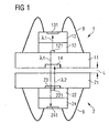
- the FIG. 1 shows an arrangement with two modules 1, 2 for bidirectional data transmission.
- the modules are designed to be complementary to one another in that the light of a first wavelength emitted by the first module 1 is detected by the second module 2 and the light of a second wavelength emitted by the second module 2 is detected by the first module 1.
- a signal transmission section L in which the signals are transmitted as a rule via glass fibers or other optical waveguides.
- a Transmission via a multimode waveguide Preferably, a Transmission via a multimode waveguide.
- the first module 1 has a carrier substrate 11, a transmitting device 12, a monitor diode 13 and a receiving device 14.
- the transmitting device 12 is preferably a VCSEL laser diode with VCSEL structure 121, which is formed in a prefabricated chip.
- the laser diode 12 is mounted upside-down, ie with the light-emitting side down on the carrier substrate 11, so that the light-emitting region 121 directly adjoins the carrier substrate 11.
- a monitor diode 13 with a photosensitive pn junction 131 is arranged, which is contacted via bonding wires.
- the monitor diode 13 detects a fraction of the light emitted by the laser diode 12. It is connected to a control device (not shown) for regulating the output power of the laser diode 1.
- the monitor diode 13 is likewise preferably designed as a prefabricated chip, preferably in an InP substrate. Alternatively, however, the monitor diode can also be monolithically integrated into the laser diode 12. In this case, a pn junction is integrated into the laser diode 12 on the side facing away from the carrier substrate 11 and contacted approximately via bonding wires.
- the laser diode 12 emits light of a first wavelength ⁇ 1, where ⁇ 1 is preferably about 1310 nm, alternatively about 1490 nm or about 1550 nm. A fraction of the light is coupled out in the direction of the monitor diode 13 from the resonator of the laser diode 12 and detected by the monitor diode 13 for monitoring purposes.
- the substrate of the laser diode 12 is for the emitted light of wavelength ⁇ . 1 transparent, as well as the substrate of the monitor diode 13.
- the substrate of the laser diode 12 consists for example of GaAs, which is transparent to light with wavelengths above 950 nm.
- the carrier substrate 11 is preferably made of silicon. Silicon is transparent for wavelengths above about 1100 nm. However, another material which is transparent to the emitted wavelength ⁇ 1 may be used as the carrier substrate.
- the receiving component 14 is integrated in the carrier substrate 11.
- the carrier substrate forms a pn junction on the side facing away from the transmitting component 12.
- the use of silicon as the carrier substrate 11 and as the material of the receiving component 14 is particularly cost-effective.
- the receiving device 14 detects light of a second wavelength ⁇ 2, which is smaller than the first wavelength ⁇ 1.
- the carrier substrate 11 is not transparent for the second wavelength ⁇ 2, so that there is an optical isolation between the transmitting component 12 and the receiving component 14 with respect to the received light of the wavelength ⁇ 2.
- the light of the wavelength ⁇ 1 emitted by the laser diode 12 radiates through the carrier substrate 11 and also the receiving diode 14 undisturbed.
- the carrier substrate must be made of a material other than silicon, since silicon is transparent to these wavelengths and thus an optical isolation between the transmitting device 12 and the receiving device 14 with respect to the received light the wavelength ⁇ 2 is no longer present.
- the carrier substrate 11 for this case consists of InP or sapphire with germanium layers.
- the complementary module 2 likewise has a carrier substrate 21, a transmitting component 22, a receiving component 24 and a monitor diode 23.
- the transmitting device is preferably again a VCSEL laser diode 22 with a light-emitting region 221 which emits light of the second wavelength ⁇ 2.
- the laser diode 22 is mounted upside-down as a chip 22 on the substrate 21.
- the substrate of the laser diode 12 is preferably made of GaAs, which is transparent to light having wavelengths above 950 nm.
- the receiving device 24 is arranged in this embodiment, which is preferably designed as a prefabricated photodiode chip (such as InP) with an integrated pn junction 241. A contacting of the receiving diode 24 via bonding wires 9. The receiving diode detects light of wavelength ⁇ 1.
- the module 2 is complementary to the other module 1.
- the monitor diode 23 is integrated in the module 2 in the carrier substrate 21.
- the monitor diode 23 is located according to FIG. 1 in this case, preferably on the side of the carrier substrate 21 facing the laser diode 22.
- the carrier substrate 21 is transparent to the light emitted by the laser diode 22 of wavelength ⁇ 2, as well as for the light emitted by the laser diode 12 of the complementary module 1 light of wavelength ⁇ 1.
- the substrate of the laser diode 22 itself is transparent only to the light of the wavelength ⁇ 1 detected by the receiver diode 204, but not to the emitted light. From the resonator of the laser diode 22 in the direction of the receiving diode 24 emitted light is therefore absorbed and does not disturb the receiving diode 24.
- the substrate of the laser diode 22 becomes accordingly as a block filter.
- a blocking filter may additionally be arranged on the side of the laser diode 22 facing the receiving diode 24. Additional blocking filters may also be provided in the module 1.
- the light emitted by the laser diode 22 of the wavelength ⁇ 2 first passes through the monitor diode 23. In this case, a small fraction of the emitted light is detected for monitoring purposes.
- the undetected portion radiates through the carrier substrate 21 and is decoupled from the module 2.
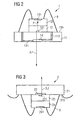
- FIG. 2 shows in more detail the structure of the module 1 of FIG. 1 ,
- the VCSEL laser diode 12 is arranged in flip-chip mounting.
- the p and n contacts of the laser diode are on the mounting side, i. arranged the carrier substrate 201 side facing. The contacting takes place via corresponding metallizations on the upper side 115 of the carrier substrate 11 (not shown).
- the monitor diode 13 On the laser diode 12, the monitor diode 13 is rear side mounted, a fraction X of the light of the laser diode 12 detected.
- the silicon carrier substrate 11 there are two plated-through holes 111, 112, which contact the receiving diode 14 integrated in the carrier substrate 101.
- all the electrical contacts are located on a plane, the mounting plane, which is formed by the one upper side 115 of the carrier substrate 11. This way can from the Assembly level 15 are then bonded in a simple manner to a leadframe, as in the FIG. 4 is still shown.
- the second module 2 of FIG. 1 is in the FIG. 3 shown in detail.
- the carrier substrate 21 is transparent both for light of the detected wavelength ⁇ 1 and for light of the emitted wavelength ⁇ 2. It is preferably made of sapphire. Sapphire is transparent for wavelengths between 850 nm and 1550 nm.
- the VCSEL laser diode 22 is in turn mounted by flip-chip mounting on one side 215 of the carrier substrate 21 so that both contacts are on the same side.
- the structure is comparable to that of the laser diode 12 of FIG. 2 ,
- the receiving diode 24 which is sensitive to another wavelength ⁇ 2, is mounted with the pn junction 24 1 on the back.
- the receiving diode 24 is a receiving diode made of an InP substrate. It serves to detect the light emitted by the module 1 of the wavelength ⁇ 1, which was emitted by the complementary module 1.
- the monitor diode 23 Integrated into the sapphire is the monitor diode 23.
- a crystalline silicon layer is preferably integrated into the sapphire, which provides a pn junction.
- the monitor diode 23 is preferably formed on the laser diode 22 side facing the carrier substrate 21. This allows a simple contacting of the monitor diode via contacts on the surface 115 of the carrier substrate.
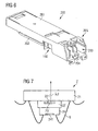
- FIG. 7 shows an alternative embodiment of the module of FIG. 3 ,
- the monitor diode 23 ' is not integrated into the carrier substrate 21, but instead in the laser diode 22' itself.
- the laser diode 22 ' is formed in this embodiment slightly larger than the receiving diode 24, so that the possibility of contacting a common contact of the laser diode 22' and the integrated monitor diode 23 'via a bonding wire 9, the carrier substrate 21 or alternatively directly to a Leadframe is contacted.
- the substrate of the laser diode 22 ' acts as a block filter for light emitted in the direction of the receiving diode 24, after it has passed the monitor diode 23'.
- the FIG. 4 shows the bidirectional module 1, 2 of FIGS. 2, 3 . 7 as a housed module 10, 20 in a standard housing.
- the carrier substrate 11, 21 can have a lens 6 located on the optical axis, which forms the emitted or received light for better coupling to an optical waveguide.
- the carrier substrate 11, 21 is arranged on a leadframe 3, which has a central recess 5 for an optical access to the module and provides the contacting of the module 1, 2. Except for the optical access 5, the arrangement of module 1, 2 and lead frame 3 is encapsulated with a non-transparent plastic compound.
- Such housing are known per se, such as from DE 102 01 102 A1 so they will not be discussed in detail.
- FIG. 5 shows a subassembly 100c with the housed module 10, 20 of the FIG. 4 connected in conjunction with an optical connector receptacle 8 for receiving an optical waveguide.
- a flexible conductor 7 with strip conductors and contact pads for contacting the connection contacts of the module 10, 20 is provided.
- the not connected to the module 10, 20 end of the flex conductor 7 is connected to a circuit board (not shown).
- modules 1, 2 according to the FIGS. 1 to 3 and 7 can be done in any optical transmitters, receivers and transceivers and the use of such modules 1, 2 Although advantageous, but not necessarily in transceivers according to the FIGS. 6 and 9 he follows.
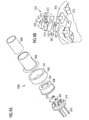
- FIG. 8 shows an alternative embodiment of a subassembly 100d, which in an optoelectronic transceiver 200 according to FIG. 6 can be used.
- two subassemblies 100d are arranged side by side in the transceiver 200 in an alignment such that the optical axis of the subassembly 100d runs parallel to the longitudinal axis of the transceiver 200 so that an optical coupling takes place via the optical ports 203, 204 can be done with an optical fiber.
- the subassembly 100d has a TO package, which in a manner known per se consists of a base plate 310 with plated through holes for a plurality of contact pins 320 and a cap 330 with an optical window 331 which is hermetically sealed to the base plate 310.
- the cap 330 is surrounded by a wall sleeve 340, on whose front side 341 a cap 350 is mounted with a coupling device 360 for receiving an optical waveguide to be connected, which is preferably a single-mode optical waveguide.
- the cover cap 350 is adjusted against a definitive fixation against the wall sleeve 340.
- Such a structure is for example from the WO 98/10319 A1 known.
- the transmission micromodule 370 has as essential components an edge-emitting semiconductor laser 371, a 45 ° prism 372 with a monitor diode 373, a beam splitter 374 with a beam-splitting, with a wavelength-selective filter provided surface 375 and a silicon substrate 376 with an integrated lens 377 on. These components are arranged on a carrier 378.
- the receiving micromodule 380 has a photodiode 382 on a carrier 381.
- a recess 311 is formed, in which the transmitting micromodule 380 is inserted.
- the transmitting micromodule 370 is arranged on the surface of the bottom plate 310.
- the carrier element 378 of the transmit micromodule is transparent to the wavelength that is detected by the photodiode 382.
- Light emitted by the semiconductor laser 371 is reflected at the beam-splitting surface 375 and emitted via the lens 377.
- received light of a different wavelength passes through the wavelength-selective filter of the beam-splitting surface 375, traverses the carrier element 387 and is detected by the photodiode 382 of the receiving micromodule 380.
- the transmit micromodule 370 and the receive micromodule 380 are each contacted via the contact pins 320 and bond wires, not shown.
- the structure described also provides in a very compact manner a subassembly with a transmitting and receiving arrangement, with the same time emitted light of a first wavelength and light of a second wavelength can be detected.
- the TO housing used preferably has external dimensions perpendicular to the optical axis of the exiting laser light of a maximum of 6.5 mm, so that mounting in small form factor (SFF) transceivers and small form factor pluggable (SFP transceivers ) Small design is possible.
- SFF small form factor
- SFP transceivers small form factor pluggable
Landscapes
- Physics & Mathematics (AREA)
- Electromagnetism (AREA)
- Engineering & Computer Science (AREA)
- Computer Networks & Wireless Communication (AREA)
- Signal Processing (AREA)
- General Physics & Mathematics (AREA)
- Optics & Photonics (AREA)
- Optical Couplings Of Light Guides (AREA)
- Semiconductor Lasers (AREA)
Claims (31)
- Emetteur-récepteur optoélectronique pour une transmission de signaux optique bidirectionnelle avec- un premier sous-ensemble optique bidirectionnel (100 ; 100a ; 100c ; 100d) destiné à émettre et recevoir simultanément des signaux optiques, et- un deuxième sous-ensemble optique bidirectionnel (100 ; 100b ; 100c ; 100d) destiné à émettre et recevoir simultanément des signaux optiques,caractérisé par- un boîtier allongé (201) ayant une largeur maximale de 13,5 mm, dans lequel les premier et deuxième sous-ensembles optiques sont conjointement disposés, notamment avec une disposition côte à côte, chacun dans une orientation telle que l'axe optique de chaque sous-ensemble soit parallèle à l'axe longitudinal du boîtier allongé (201), et- une interface optique (205) destinée à coupler deux câbles à fibres optiques, chaque câble à fibres optiques pouvant être couplé optiquement avec un des deux sous-ensembles (100 ; 100a ; 1 00b ; 104c ; 100d).
- Emetteur-récepteur selon la revendication 1, comportant en outre un multiplexeur (250) et un démultiplexeur (240), où- le démultiplexeur (240) répartit un flux de données électriques à transmettre par l'émetteur-récepteur d'une largeur de bande prédéterminée en un premier et un deuxième flux de données partiel à transmettre d'une largeur de bande plus faible,- le premier flux de données partiel à transmettre est amené au premier sous-ensemble et le deuxième flux de données partiel à transmettre est amené au deuxième sous-ensemble, et- les premier et deuxième flux de données à transmettre sont émis par les premier et deuxième sous-ensembles sous forme de signaux optiques, et où- le premier sous-ensemble et le deuxième sous-ensemble reçoivent, simultanément à l'émission de signaux optiques, un premier flux de données partiel optique à recevoir et un deuxième flux de données partiel optique à recevoir chacun d'une largeur de bande définie, les convertissent en des signaux électriques et les amènent au multiplexeur (250) qui regroupe les deux flux de données partiels reçus en un flux de données électrique reçu d'une largeur de bande prédéterminée plus élevée.
- Emetteur-récepteur selon la revendication 2, où le démultiplexeur (240) est un démultiplexeur 1 vers 2 et le multiplexeur (250) est un multiplexeur 2 vers 1 et que les largeurs de bande prédéterminées du signal de données à émettre et à recevoir sont identiques.
- Emetteur-récepteur selon la revendication 1, où le multiplexeur (250) et le démultiplexeur (240) sont intégrés dans l'émetteur-récepteur (200).
- Emetteur-récepteur selon la revendication 1, où le premier sous-ensemble comporte :- un composant d'émission (12) qui émet un rayon lumineux d'une première longueur d'onde (λ1),- un composant de réception (14) qui détecte un rayon lumineux d'une deuxième longueur d'onde (λ2),- un substrat de support (11), transparent pour le rayon lumineux de la première longueur d'onde, sur lequel est disposé le composant d'émission, et- un composant de contrôle (13) qui détecte une fraction du rayon lumineux émis par le composant d'émission (12),où- le composant de réception (14) est intégré dans le substrat de support (11),- le composant de réception (14) et le composant d'émission (12) sont disposés l'un derrière l'autre par rapport à la direction du rayon lumineux émis ou reçu,- le composant de réception (14) est transparent optiquement au rayon lumineux de la première longueur d'onde (11) et- le rayon lumineux émis par le composant d'émission (12) traverse le substrat de support (11) et le composant de réception (14).
- Emetteur-récepteur selon la revendication 5, où le composant d'émission (12) est monté sur le substrat de support (11) avec sa partie supérieure tournée vers le bas.
- Emetteur-récepteur selon la revendication 5, où le composant de réception (14) est intégré dans le substrat de support (11) sur le côté de celui-ci opposé au composant d'émission (12).
- Emetteur-récepteur selon la revendication 5, où le composant de réception (14) intégré dans le substrat de support forme un passage pn intégré dans le substrat de support.
- Emetteur-récepteur selon la revendication 7, caractérisé en ce que le substrat de support (11) comporte deux contacts traversant (111, 112) qui partent du côté (115) du substrat de support (11) tourné vers le composant d'émission (12) et mettent en contact le composant de réception (14).
- Emetteur-récepteur selon la revendication 5, où le substrat de support (11) n'est pas transparent pour le rayon lumineux de la deuxième longueur d'onde (λ2).
- Emetteur-récepteur selon la revendication 5, où la première longueur d'onde (λ1) est plus grande que la deuxième longueur d'onde (λ2).
- Emetteur-récepteur selon la revendication 11, où la première longueur d'onde (λ1) est de 1310 nm, 1490 nm ou 1550 nm et la deuxième longueur d'onde (λ2) de 850 nm ou 1310 nm.
- Emetteur-récepteur selon la revendication 5, où le substrat de support (11) est composé de silicium.
- Emetteur-récepteur selon la revendication 5, où le composant de contrôle (13) est disposé sur le côté du composant d'émission (12) opposé au substrat de support (11).
- Emetteur-récepteur selon la revendication 5, où le composant d'émission est formé en tant que puce laser (12) et que le composant de contrôle est formé en tant que puce de diodes de contrôle (13).
- Emetteur-récepteur selon la revendication 5, où le composant de contrôle est intégré dans le composant d'émission sur le côté du composant d'émission opposé au substrat de support.
- Emetteur-récepteur selon la revendication 1, où le deuxième sous-ensemble comporte :- un composant d'émission (22) qui émet un rayon lumineux d'une deuxième longueur d'onde (λ2),- un composant de réception (24) qui détecte un rayon lumineux d'une première longueur d'onde (λ1),- un substrat de support (21), transparent pour le rayon lumineux de la première longueur d'onde (λ1) et de la deuxième longueur d'onde (λ2), sur lequel est disposé le composant d'émission (22), et- un composant de contrôle (23) qui détecte une fraction du rayon lumineux émis par le composant d'émission (22), où- le composant de réception (24) et le composant d'émission (22) sont disposés l'un derrière l'autre par rapport à la direction du rayon lumineux émis ou reçu,- le composant d'émission (22) est transparent optiquement pour le rayon lumineux de la première longueur d'onde,- le rayon lumineux émis par le composant d'émission (22) traverse le substrat de support (21) et- le rayon lumineux reçu par le composant de réception (24) traverse le substrat de support (21) et le composant d'émission (22).
- Emetteur-récepteur selon la revendication 17, où le composant de contrôle (23) est intégré dans le substrat de support (21).
- Emetteur-récepteur selon la revendication 18, où le composant de contrôle (23) est intégré dans le substrat de support (21) sur le côté de celui-ci tourné vers le composant d'émission (22).
- Emetteur-récepteur selon la revendication 18, où le composant de contrôle (23) intégré dans le substrat de support (21) forme un passage pn dans le substrat de support (21).
- Emetteur-récepteur selon la revendication 17, où le composant de contrôle (23') est intégré dans le composant d'émission (22').
- Emetteur-récepteur selon la revendication 17, où le composant d'émission (22) est disposé sur le substrat de support (21) avec sa partie supérieure tournée vers le bas.
- Emetteur-récepteur selon la revendication 17, où la couche photosensible (241) du composant de réception (24) est disposée sur le côté du composant de réception (24) opposé au composant d'émission (22).
- Emetteur-récepteur selon la revendication 17, où le substrat du composant d'émission (22) n'est pas transparent pour le rayon lumineux émis de la deuxième longueur d'onde (λ2).
- Emetteur-récepteur selon la revendication 17, où la première longueur d'onde (λ1) est plus grande que la deuxième longueur d'onde (12).
- Emetteur-récepteur selon la revendication 25, où la première longueur d'onde (λ1) est de 1310 nm, 1490 nm ou 1550 nm et la deuxième longueur d'onde (12) de 850 nm ou 1310 nm.
- Emetteur-récepteur selon la revendication 17, où le substrat de support (21) est composé de saphir.
- Emetteur-récepteur selon la revendication 17, où le composant d'émission est formé en tant que puce laser (22) et que le composant de réception est formé en tant que puce de photodiodes (24).
- Emetteur-récepteur selon la revendication 17, où le composant d'émission est formé par une diode laser émettant verticalement.
- Emetteur-récepteur selon la revendication 1, où un sous-ensemble comporte :- un micromodule d'émission (370) qui comporte sur un premier élément de support (378) un composant laser (371) qui émet un rayon lumineux d'une première longueur d'onde,- un micromodule de réception (380) qui comporte sur un deuxième élément de support (381) une photodiode (382) qui détecte un rayon lumineux d'une deuxième longueur d'onde, et- un boîtier TO avec une plaque de fond (310) qui sert d'agencement pour le micromodule d'émission et le micromodule de réception, où- le micromodule d'émission (370) et le micromodule de réception (380) sont disposés l'un derrière l'autre par rapport au rayon lumineux émis ou à détecter, et- le premier élément de support (378) du micromodule d'émission (370) est transparent au rayon lumineux à détecter.
- Emetteur-récepteur selon la revendication 30, où la plaque de fond (310) du boîtier TO présente un évidemment (311) qui sert de réceptacle pour le micromodule de réception (380) et que le micromodule d'émission (370) est agencé au-dessus de celui-ci sur la plaque de fond (310).
Applications Claiming Priority (4)
| Application Number | Priority Date | Filing Date | Title |
|---|---|---|---|
| DE10348675A DE10348675B3 (de) | 2003-10-15 | 2003-10-15 | Modul für eine bidirektionale optische Signalübertragung |
| DE10348675 | 2003-10-15 | ||
| US769287 | 2004-01-30 | ||
| US10/769,287 US7418208B2 (en) | 2003-10-15 | 2004-01-30 | Optoelectronic transceiver for a bidirectional optical signal transmission |
Publications (3)
| Publication Number | Publication Date |
|---|---|
| EP1524786A2 EP1524786A2 (fr) | 2005-04-20 |
| EP1524786A3 EP1524786A3 (fr) | 2005-11-02 |
| EP1524786B1 true EP1524786B1 (fr) | 2008-09-10 |
Family
ID=34379087
Family Applications (1)
| Application Number | Title | Priority Date | Filing Date |
|---|---|---|---|
| EP20040077681 Expired - Lifetime EP1524786B1 (fr) | 2003-10-15 | 2004-09-28 | Emetteur-recepteur optoelectronique pour la transmission optique bidirectionelle |
Country Status (1)
| Country | Link |
|---|---|
| EP (1) | EP1524786B1 (fr) |
Families Citing this family (1)
| Publication number | Priority date | Publication date | Assignee | Title |
|---|---|---|---|---|
| CN112865872B (zh) * | 2021-03-06 | 2025-01-24 | 珠海思开达技术有限公司 | 模拟光传输模块 |
Family Cites Families (4)
| Publication number | Priority date | Publication date | Assignee | Title |
|---|---|---|---|---|
| DE4444470A1 (de) * | 1994-11-29 | 1996-05-30 | Hertz Inst Heinrich | Sender/Empfänger-Anordnung für ein optisches Duplexsystem |
| JPH11305078A (ja) * | 1998-04-27 | 1999-11-05 | Oki Electric Ind Co Ltd | 光送受信モジュール |
| DE10064599A1 (de) * | 2000-12-18 | 2002-07-04 | Infineon Technologies Ag | Sende-/Empfangsmodul für eine bidirektionale optische Nachrichten-und Signalübertragung |
| GB2378068B (en) * | 2001-07-27 | 2005-05-04 | Motorola Inc | Bipolar differential amplifier |
-
2004
- 2004-09-28 EP EP20040077681 patent/EP1524786B1/fr not_active Expired - Lifetime
Also Published As
| Publication number | Publication date |
|---|---|
| EP1524786A3 (fr) | 2005-11-02 |
| EP1524786A2 (fr) | 2005-04-20 |
Similar Documents
| Publication | Publication Date | Title |
|---|---|---|
| DE10348675B3 (de) | Modul für eine bidirektionale optische Signalübertragung | |
| DE69409204T2 (de) | Optischer, bidirektionaler Übertragungsmodul | |
| DE69700230T2 (de) | Laserlichtquelle | |
| DE10105943B4 (de) | Faseroptisches Linsensystem zum Koppeln von Fasern mit oberflächenbefestigten Bauelementen | |
| EP1311890B1 (fr) | Bloc opto-electronique destine a multiplexer et / ou a demultiplexer des signaux optiques | |
| EP0600267B1 (fr) | Module optique émetteur-récepteur bidirectionnel | |
| DE102014103330B4 (de) | Bidirektionales optisches Datenkommunikationsmodul und Verfahren für eine optische Kommunikation | |
| EP0463214B1 (fr) | Module d'émission et de réception pour la transmission bidirectionnelle optique de communication et de signal | |
| DE102012200254B4 (de) | Optische Verbindungssysteme mit Stecker, welcher eine optische Biegung hat, und Benutzungsverfahren | |
| DE10037902C2 (de) | Optisches bidirektionales Sende- und Empfangsmodul mit einem Stiftkörper mit integriertem WDM-Filter | |
| DE60032338T2 (de) | Optische nachrichtenübertragungsvorrichtung | |
| DE69916914T2 (de) | LD/PD Modul und LED/PD Modul | |
| DE60131928T2 (de) | Vorrichtung zur bidirektionalen Signalübertragung mittels Licht | |
| EP0383138A2 (fr) | Dispositif pour la réception optique directe d'une pluralité de longueurs d'ondes | |
| DE69836058T2 (de) | Mehrkanaliges optisches Empfänger-/Sendersystem | |
| EP1425619A1 (fr) | Ensemble emetteur-recepteur pour transmission de donnees optique bidirectionnelle | |
| DE19917596B4 (de) | Bidirektionales optisches Kommunikationsbauteil und bidirektionale optische Kommunikationsvorrichtung | |
| DE102012215517A1 (de) | Ein optisches Kopplungssystem zur Verwendung in einem optischen Kommunikationsmodul, ein optisches Kommunikationsmodul, das das optische Kopplungssystem integriert, und ein Verfahren | |
| DE10312500A1 (de) | Anordnung zum Multiplexen und/oder Demultiplexen optischer Signale einer Mehrzahl von Wellenlängen | |
| WO2002084358A1 (fr) | Module d'emission destine a une transmission de signal optique | |
| DE69015588T2 (de) | Optischer Kopf integrierbar in einem hybriden Schaltkreis. | |
| DE60130150T2 (de) | Photonische signalmatrix in integrierter schaltung | |
| DE3737251C2 (de) | Halbleiter-Trägerelement für ein elektro-optisches Modul | |
| EP1145063B1 (fr) | Composant electro-optique a canaux multiples | |
| EP1524786A2 (fr) | Emetteur-recepteur optoelectronique pour la transmission optique bidirectionelle |
Legal Events
| Date | Code | Title | Description |
|---|---|---|---|
| PUAI | Public reference made under article 153(3) epc to a published international application that has entered the european phase |
Free format text: ORIGINAL CODE: 0009012 |
|
| AK | Designated contracting states |
Kind code of ref document: A2 Designated state(s): AT BE BG CH CY CZ DE DK EE ES FI FR GB GR HU IE IT LI LU MC NL PL PT RO SE SI SK TR |
|
| AX | Request for extension of the european patent |
Extension state: AL HR LT LV MK |
|
| PUAL | Search report despatched |
Free format text: ORIGINAL CODE: 0009013 |
|
| AK | Designated contracting states |
Kind code of ref document: A3 Designated state(s): AT BE BG CH CY CZ DE DK EE ES FI FR GB GR HU IE IT LI LU MC NL PL PT RO SE SI SK TR |
|
| AX | Request for extension of the european patent |
Extension state: AL HR LT LV MK |
|
| 17P | Request for examination filed |
Effective date: 20060427 |
|
| AKX | Designation fees paid |
Designated state(s): DE FR GB |
|
| RAP1 | Party data changed (applicant data changed or rights of an application transferred) |
Owner name: FINISAR CORPORATION |
|
| GRAP | Despatch of communication of intention to grant a patent |
Free format text: ORIGINAL CODE: EPIDOSNIGR1 |
|
| GRAS | Grant fee paid |
Free format text: ORIGINAL CODE: EPIDOSNIGR3 |
|
| GRAA | (expected) grant |
Free format text: ORIGINAL CODE: 0009210 |
|
| AK | Designated contracting states |
Kind code of ref document: B1 Designated state(s): DE FR GB |
|
| REG | Reference to a national code |
Ref country code: GB Ref legal event code: FG4D Free format text: NOT ENGLISH |
|
| REF | Corresponds to: |
Ref document number: 502004008013 Country of ref document: DE Date of ref document: 20081023 Kind code of ref document: P |
|
| PLBE | No opposition filed within time limit |
Free format text: ORIGINAL CODE: 0009261 |
|
| STAA | Information on the status of an ep patent application or granted ep patent |
Free format text: STATUS: NO OPPOSITION FILED WITHIN TIME LIMIT |
|
| 26N | No opposition filed |
Effective date: 20090611 |
|
| PG25 | Lapsed in a contracting state [announced via postgrant information from national office to epo] |
Ref country code: DE Free format text: LAPSE BECAUSE OF NON-PAYMENT OF DUE FEES Effective date: 20090401 |
|
| REG | Reference to a national code |
Ref country code: FR Ref legal event code: ST Effective date: 20090731 |
|
| PG25 | Lapsed in a contracting state [announced via postgrant information from national office to epo] |
Ref country code: FR Free format text: LAPSE BECAUSE OF NON-PAYMENT OF DUE FEES Effective date: 20081110 |
|
| PGFP | Annual fee paid to national office [announced via postgrant information from national office to epo] |
Ref country code: GB Payment date: 20140929 Year of fee payment: 11 |
|
| GBPC | Gb: european patent ceased through non-payment of renewal fee |
Effective date: 20150928 |
|
| PG25 | Lapsed in a contracting state [announced via postgrant information from national office to epo] |
Ref country code: GB Free format text: LAPSE BECAUSE OF NON-PAYMENT OF DUE FEES Effective date: 20150928 |