EP1524738A1 - Isolierende Kohlebürstenführung - Google Patents
Isolierende Kohlebürstenführung Download PDFInfo
- Publication number
- EP1524738A1 EP1524738A1 EP04022219A EP04022219A EP1524738A1 EP 1524738 A1 EP1524738 A1 EP 1524738A1 EP 04022219 A EP04022219 A EP 04022219A EP 04022219 A EP04022219 A EP 04022219A EP 1524738 A1 EP1524738 A1 EP 1524738A1
- Authority
- EP
- European Patent Office
- Prior art keywords
- carbon brush
- brush guide
- guide
- layer
- power transmission
- Prior art date
- Legal status (The legal status is an assumption and is not a legal conclusion. Google has not performed a legal analysis and makes no representation as to the accuracy of the status listed.)
- Granted
Links
- 229910052799 carbon Inorganic materials 0.000 claims abstract description 155
- OKTJSMMVPCPJKN-UHFFFAOYSA-N Carbon Chemical compound [C] OKTJSMMVPCPJKN-UHFFFAOYSA-N 0.000 claims abstract description 153
- 229910052782 aluminium Inorganic materials 0.000 claims abstract description 15
- XAGFODPZIPBFFR-UHFFFAOYSA-N aluminium Chemical compound [Al] XAGFODPZIPBFFR-UHFFFAOYSA-N 0.000 claims abstract description 15
- 238000004519 manufacturing process Methods 0.000 claims abstract description 10
- 230000005540 biological transmission Effects 0.000 claims description 18
- 238000007743 anodising Methods 0.000 claims description 8
- 238000005452 bending Methods 0.000 claims description 8
- 229910052751 metal Inorganic materials 0.000 claims description 6
- 239000002184 metal Substances 0.000 claims description 6
- 238000000034 method Methods 0.000 claims description 3
- TWNQGVIAIRXVLR-UHFFFAOYSA-N oxo(oxoalumanyloxy)alumane Chemical compound O=[Al]O[Al]=O TWNQGVIAIRXVLR-UHFFFAOYSA-N 0.000 claims description 3
- 239000004033 plastic Substances 0.000 claims description 3
- 239000011265 semifinished product Substances 0.000 claims description 3
- 230000005855 radiation Effects 0.000 abstract description 5
- PNEYBMLMFCGWSK-UHFFFAOYSA-N Alumina Chemical compound [O-2].[O-2].[O-2].[Al+3].[Al+3] PNEYBMLMFCGWSK-UHFFFAOYSA-N 0.000 abstract description 4
- 238000010521 absorption reaction Methods 0.000 abstract 1
- 239000004411 aluminium Substances 0.000 abstract 1
- 238000009413 insulation Methods 0.000 description 10
- 239000003245 coal Substances 0.000 description 5
- 238000005406 washing Methods 0.000 description 3
- 238000004804 winding Methods 0.000 description 3
- XEEYBQQBJWHFJM-UHFFFAOYSA-N Iron Chemical compound [Fe] XEEYBQQBJWHFJM-UHFFFAOYSA-N 0.000 description 2
- 229910000831 Steel Inorganic materials 0.000 description 2
- RQMIWLMVTCKXAQ-UHFFFAOYSA-N [AlH3].[C] Chemical compound [AlH3].[C] RQMIWLMVTCKXAQ-UHFFFAOYSA-N 0.000 description 2
- AZDRQVAHHNSJOQ-UHFFFAOYSA-N alumane Chemical group [AlH3] AZDRQVAHHNSJOQ-UHFFFAOYSA-N 0.000 description 2
- 238000002048 anodisation reaction Methods 0.000 description 2
- 150000001721 carbon Chemical class 0.000 description 2
- 238000004040 coloring Methods 0.000 description 2
- 230000000694 effects Effects 0.000 description 2
- 239000003973 paint Substances 0.000 description 2
- 239000010959 steel Substances 0.000 description 2
- 229910018072 Al 2 O 3 Inorganic materials 0.000 description 1
- 229910001369 Brass Inorganic materials 0.000 description 1
- 239000004793 Polystyrene Substances 0.000 description 1
- QVGXLLKOCUKJST-UHFFFAOYSA-N atomic oxygen Chemical compound [O] QVGXLLKOCUKJST-UHFFFAOYSA-N 0.000 description 1
- 230000015572 biosynthetic process Effects 0.000 description 1
- 239000010951 brass Substances 0.000 description 1
- 239000003086 colorant Substances 0.000 description 1
- 229940126214 compound 3 Drugs 0.000 description 1
- 239000003822 epoxy resin Substances 0.000 description 1
- 230000002349 favourable effect Effects 0.000 description 1
- 230000017525 heat dissipation Effects 0.000 description 1
- 238000010438 heat treatment Methods 0.000 description 1
- 229910052742 iron Inorganic materials 0.000 description 1
- 238000002955 isolation Methods 0.000 description 1
- 229910052760 oxygen Inorganic materials 0.000 description 1
- 239000001301 oxygen Substances 0.000 description 1
- 239000005011 phenolic resin Substances 0.000 description 1
- 229920000647 polyepoxide Polymers 0.000 description 1
- 229920002223 polystyrene Polymers 0.000 description 1
- -1 polytetrafluoroethylene Polymers 0.000 description 1
- 229920001343 polytetrafluoroethylene Polymers 0.000 description 1
- 239000004810 polytetrafluoroethylene Substances 0.000 description 1
- 238000003860 storage Methods 0.000 description 1
- 239000000126 substance Substances 0.000 description 1
Images
Classifications
-
- H—ELECTRICITY
- H01—ELECTRIC ELEMENTS
- H01R—ELECTRICALLY-CONDUCTIVE CONNECTIONS; STRUCTURAL ASSOCIATIONS OF A PLURALITY OF MUTUALLY-INSULATED ELECTRICAL CONNECTING ELEMENTS; COUPLING DEVICES; CURRENT COLLECTORS
- H01R39/00—Rotary current collectors, distributors or interrupters
- H01R39/02—Details for dynamo electric machines
- H01R39/38—Brush holders
- H01R39/40—Brush holders enabling brush movement within holder during current collection
-
- H—ELECTRICITY
- H01—ELECTRIC ELEMENTS
- H01R—ELECTRICALLY-CONDUCTIVE CONNECTIONS; STRUCTURAL ASSOCIATIONS OF A PLURALITY OF MUTUALLY-INSULATED ELECTRICAL CONNECTING ELEMENTS; COUPLING DEVICES; CURRENT COLLECTORS
- H01R39/00—Rotary current collectors, distributors or interrupters
- H01R39/02—Details for dynamo electric machines
- H01R39/38—Brush holders
- H01R39/388—Brush holders characterised by the material of the brush holder
-
- H—ELECTRICITY
- H01—ELECTRIC ELEMENTS
- H01R—ELECTRICALLY-CONDUCTIVE CONNECTIONS; STRUCTURAL ASSOCIATIONS OF A PLURALITY OF MUTUALLY-INSULATED ELECTRICAL CONNECTING ELEMENTS; COUPLING DEVICES; CURRENT COLLECTORS
- H01R39/00—Rotary current collectors, distributors or interrupters
- H01R39/02—Details for dynamo electric machines
- H01R39/18—Contacts for co-operation with commutator or slip-ring, e.g. contact brush
- H01R39/24—Laminated contacts; Wire contacts, e.g. metallic brush, carbon fibres
Definitions
- the invention relates to a carbon brush guide for a power transmission unit a dynamo-electric machine, in particular for an electric motor, wherein the power transmission unit at least one carbon brush, in particular is designed as a multilayer carbon brush, and a carbon brush guide Metal consists of at least the carbon brush side has an insulating layer.
- From DE 101 57 604 A1 is a carbon brush guide of an electric motor known, consisting of a tinned with an insulating layer Steel sheet exists and which is particularly suitable for a multilayer coal.
- the insulation layer applied in the carbon brush guide serves to avoid it a short-circuit current or cross-flow between the individual Layers of multilayer carbon brush.
- insulation layer is a paint like Phenol resin, epoxy resin or polystyrene paint on the carbon brushed steel sheet applied. When using such isolation between the Carbon brush guide and the multi-layer carbon brush, the gap be tolerated closely.
- the disadvantage of such insulation is that the insulation layer thermally and mechanically can not be stressed as much as a pure metal guide.
- carbon brush guides are known from the prior art, the usually consist of brass sheet and have no insulation layer. Large gaps must be between such an electrically conductive carbon brush guide and a multi-layer carbon brush to allow the multilayer carbon brush As a rule, only with a maximum of one carbon layer, the carbon brush guide touched.
- the carbon brushes within the carbon brush guide can tilt so that at least two different layers of carbon brush with the guide come in line contact. This results in short-circuit currents in this position which leads to excessive heating of motor windings and collector and lead to increased brush wear.
- the carbon brush runs in this tilting position over a brush edge, which still unnecessary brush noise is produced.
- the invention is therefore the object of a carbon brush guide of the type mentioned insulation between a carbon brush and their To provide leadership that is thermally and mechanically strong load, and that the carbon brush guide is economical to manufacture. It should on the one hand the Carbon brush guide be designed so that when the intended Use in a dynamo-electric machine no unnecessary brush noise arise and on the other hand, the carbon brush the smallest possible Wear has.
- the carbon brush guide Aluminum form since aluminum has very good thermo-electrical properties having.
- the aluminum forms anodising non-conductive very thin oxide layer. This alumina layer or
- Eloxal Anlagen usually has a thickness of 5 microns to 30 microns and is still there extremely durable and thermally and mechanically resistant. additionally advantageously remain the good thermal properties of aluminum receive.
- the anodized layer advantageously in a dark color, preferably in black.
- the power transmission unit consisting of the carbon brush guide and the Carbon brush can also have a holder for holding the carbon brush guide include.
- This holder is generally made of plastic. So that Heat in such a power transmission unit of the carbon brush guide can be dissipated again, this carbon brush is advantageously not completely surrounded by the plastic holder. So the heat can over the reassigning outer surfaces of carbon brush guide radiated again become.
- the carbon brush and / or the carbon brush guide is designed so that the carbon brush and the carbon brush guide are in the crack areas of the Can not touch the anodizing layer. This results in a formation of short-circuit currents, especially between the layers of a multilayer carbon brush, safely prevented.
- the carbon brush at its longitudinal edges with a chamfer be provided so as to provide the required distance to the crack areas of Eloxal Anlagen the carbon brush guide produce.
- the carbon brush guide 5 is a power transmission unit intended for a washing machine electric motor.
- This washing machine electric motor is preferably a universal motor.
- the universal motor (not shown) includes, among other things, a stator, a rotor, a Commutator, two bearing plates and the power transmission unit, which in the essentially from the carbon brush guide 5, the carbon brush 1 and the holder. 8 consists.
- the rotor and the stator are each packed with iron and corresponding Provided windings for generating magnetic fields.
- the commutator is mechanically connected to the rotor shaft and electrically connected to the rotor windings.
- the stator is mechanically attached to the bearing plates, which are also used for Serve recording and storage of the rotor shaft. At one of the bearing signs is among other things, the holder 8 of the power transmission unit attached.
- the carbon brushes are designed as multi-layer carbon brushes to a better To achieve commutation.
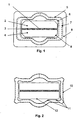
- 1 shows a two-layer carbon brush 1, consisting of two interconnected by means of a non-conductive compound 3 conductive carbon halves 2, 4 consists.
- the one end face of the carbon brush 1 is on the commutator, creating a conductive connection between a Commutator blade and the carbon brush is formed, and the other end of the Carbon brush 1 is contacted with a Stromzhoummungslitze, whereby the two Coal halves 2 and 4 are electrically connected to each other at the contact point.
- the carbon brush guide 5 is shown purely schematically in FIG. In the present Embodiment, this carbon brush guide 5 is made of an aluminum sheet executed, which is anodized on both sides. Thus, the carbon brush guide 5 equipped on both sides with a non-conductive aluminum oxide or Eloxal Anlagen 6, 7.
- the carbon brush 1 facing layer 6 causes the two Coal halves 2 and 4 in a possible touch of the carbon brush guide 5 not be short-circuited. Such a contact occurs in particular, when the carbon brush 1 tilts slightly in operation in the carbon brush guide 5.
- the Insulating layer 6 avoids a short circuit between the carbon halves 2 and 4. As a result, the coal halves 2, 4 are always energized evenly. Such Energizing the coal halves 2, 4 leads to a uniform and low Brush wear.
- the outer wall of the carbon brush guide is also 5 equipped with a non-conductive anodized 7. This will be possible leakage currents between the conductive end shield and the carbon brush guide 5 avoided. This is especially important if the holder 8 due to its shape is not sufficient distance between the End shield and the carbon brush guide 5 can ensure.
- the carbon brush guide 6 directly to the Bearing shield mounted because the outer anodized layer 7 is sufficiently insulating.
- the power transmission unit can be made even cheaper be because the holder 8 of the carbon brush guide 5 can be dispensed with.
- the anodized layer 6, 7 is in a thickness of 15 microns on the carbon brush guide. 5 applied. But other layer thicknesses between 5 and 30 microns are possible. Such anodized layers 6, 7 are sufficiently insulating and very wear-resistant and resistant to climatic and chemical influences. Because the thickness of the Eloxal Anlagen 6 is very uniform and a touch of the carbon brush 1 with the carbon brush guide 5 due to the non-conductive anodized layer 6 is possible, the guide gap (clearance) between carbon brush 1 and carbon brush guide 5 are tolerated very tightly. A transverse game according to DIN 43008 between the carbon brush 1 and the carbon brush guide 5 is in Present embodiment readily complied with and tilting the Carbon brush 1 in the carbon brush guide 5 is thus avoided. By a Such precise guidance of the carbon brush 1 is excluded that a Carbon brush edge over a commutator blade runs and thus a corresponding Brush noise generated.
- the anodizing layer 6 of the carbon brush guide 5 is on the carbon brushes. 1 facing surface executed in a black color.
- Such a coloring the Eloxal Mrs 6 is in an anodization by a suitable choice of Production parameters easily achievable. There are others, too dark, colors conceivable that can absorb heat radiation well. By this special coloring is achieved that in the area of the carbon brush 1 resulting heat, which is the contact point between carbon brush 1 and commutator and radiate the carbon brush 1 in the form of heat radiation, from the Eloxal layer 6 is well absorbed.
- the heat absorbed by the anodizing layer 6 is transferred to the aluminum carbon brush guide 5 and turn away at the carbon brushes 1 Side again radiated.
- the holder 8 of the carbon brush guide 5 is designed so that the carbon brush guide 5 is not completely enclosed by the holder 8.
- the free outside Surfaces of the carbon brush guide 5 then radiate heat to the Environment.
- the heat radiation or the heat release of the exposed Surfaces of the carbon brush guide is additionally favored when the carbon brush guide is arranged in an air flow generated by the engine itself. This air flow is through a suitable design of the bearing plates and / or of the stator influenced.
- the no holder. 8 contains the carbon brush guide 5 in direct contact with the bearing plate on Bearing shield of the engine attached.
- the heat dissipation of the area the carbon brush 1 additionally favors, since the of the carbon brush guide 5 absorbed heat is delivered directly to the bearing plate.
- Such direct attachment of the carbon brush guide 5 on the bearing plate is determined by the non-conductive outer Eloxal Mrs 7 allows.
- an aluminum sheet For the advantageous production of the carbon brush guide 5 according to the invention anodized in an initial manufacturing step an aluminum sheet. Out of such Anodized aluminum sheet is a semi-finished product in a second production step made for the carbon brush guide 5. In the present embodiment is The semi-finished stamped from the anodized aluminum sheet, but also other suitable methods are conceivable. This semi-finished product is then in a third Production step to the carbon brush guide 5 bent. In a one-sided Anodized aluminum sheet, the bending process is designed so that the anodized layer 6 lies inside, so in the guide region of the carbon brush. 1
- an anodized layer may crack in the bending area. Such cracks can reduce the insulating effect of the anodizing layer 6 with respect to the carbon brush 1 in the bending region.
- 2 shows a favorable design possibility of a carbon brush guide 10, in which each deformation region of the carbon brush guide begins and ends with a convex curvature 11, that is, a curvature 11 facing away from the carbon brush 12. This ensures that the carbon brush 12 does not move when displaced curved surfaces of the carbon brush guide 10 can touch. Thus, a contact of the carbon brush 12 is excluded with the areas that may have possible cracks in the anodized layer 6. Over time, the exposed areas of aluminum within the cracks by the oxygen in the air automatically become an insulating layer of Al 2 O 3 again .
- An alternative power transmission unit includes a special design of the Carbon brush 1, wherein the longitudinal edges of the carbon brush 1 each have a chamfer. 9 have, as shown in Fig. 1. Also in this version will ensures that the carbon brush does not reach the bending areas when relocating the carbon brush guide 5 can touch.
- the present invention is not limited to the use of multilayer carbon brushes limited, but it can also be applied for block carbon brushes become.
- the same embodiment of the carbon brush guide for both carbon brush types or for AC and DC motors be used.
Landscapes
- Motor Or Generator Current Collectors (AREA)
- Apparatus For Radiation Diagnosis (AREA)
- Fishing Rods (AREA)
Abstract
Description
Claims (10)
- Kohlebürstenführung für eine Stromübertragungseinheit einer dynamo-elektrischen Maschine, insbesondere für einen Elektromotor, wobei die Stromübertragungseinheit mindestens aus einer Kohlebürste (1), die insbesondere als Mehrschichtkohlebürste ausgeführt ist, und einer Kohlebürstenführung (5) aus Metall besteht, die mindestens kohlebürstenseitig eine isolierende Schicht aufweist, dadurch gekennzeichnet, dass die Kohlebürstenführung (5) in Aluminium mit mindestens einer Aluminiumoxid-Schicht (6, 7) ausgeführt ist.
- Kohlebürstenführung nach Anspruch 1, dadurch gekennzeichnet, dass die Aluminiumoxid-Schicht (6,7) eine künstlich aufgebrachte Eloxal-Schicht ist.
- Kohlebürstenführung nach Anspruch 1 oder 2, dadurch gekennzeichnet, dass die Eloxalschicht (6, 7) eine Dicke aufweist, die zwischen 5 µm bis 30 µm liegt.
- Kohlebürstenführung nach einem der Ansprüche 1 bis 3, dadurch gekennzeichnet, dass mindestens kohlebürstenseitig die Eloxalschicht (6, 7) der Kohlebürstenführung (5) zur Absorption von Wärmestrahlen geeignet ist.
- Kohlebürstenführung nach Anspruch 4, dadurch gekennzeichnet, dass mindestens kohlebürstenseitig die Eloxalschicht (6, 7) der Kohlebürstenführung (5) dunkel, insbesondere schwarz, eingefärbt ist.
- Stromübertragungseinheit mit einer Kohlebürstenführung nach einem der Ansprüche 1 bis 5 und einer Kohlebürste, dadurch gekennzeichnet, dass die Kohlebürste (1, 12) und/oder die Kohlebürstenführung (5, 10) so geformt sind, dass sich die Kohlebürste (1, 12) und die Kohlebürstenführung (5, 10) nur an nicht gekrümmten Flächen der Kohlebürstenführung (5, 10) berühren können.
- Stromübertragungseinheit nach Anspruch 6, die zusätzlich einen Halter (8) aus Kunststoff zur Aufnahme der Kohlebürstenführung (5) enthält, dadurch gekennzeichnet, dass die Kohlebürstenführung (5) nicht vollständig vom Halter (8) umfasst ist.
- Kohlebürste für eine Stromübertragungseinheit nach einem der Ansprüche 6 oder 7, dadurch gekennzeichnet, dass die Kohlebürste (1) an allen Längskanten eine Fase (9) aufweist.
- Dynamo-elektrische Maschine, insbesondere ein Elektromotor, dadurch gekennzeichnet, dass die dynamo-elektrische Maschine mit einer Kohlebürstenführung (5) nach einem der Ansprüche 1 bis 5, mit einer Kohlebürste nach Anspruch 8 und/oder mit einer Stromübertragungseinheit nach einem der Ansprüchen 6 oder 7 versehen ist.
- Herstellungsverfahren einer Kohlebürstenführung für eine Stromübertragungseinheit einer dynamo-elektrischen Maschine, insbesondere eines Elektromotors, dadurch gekennzeichnet, dass das Verfahren folgende Schritte enthält:a. Eloxieren eines Aluminiumblechabschnitts mindestens auf einer Seite,b. Fertigen eines Halbzeugs für die Kohlenbürstenführung (5, 10) aus dem eloxiertem Aluminiumblechabschnitt undc. Biegen des Halbzeugs zu einer Kohlebürstenführung (5, 10).
Applications Claiming Priority (2)
| Application Number | Priority Date | Filing Date | Title |
|---|---|---|---|
| DE10347764A DE10347764A1 (de) | 2003-10-14 | 2003-10-14 | Isolierte Kohlebürstenführung |
| DE10347764 | 2003-10-14 |
Publications (2)
| Publication Number | Publication Date |
|---|---|
| EP1524738A1 true EP1524738A1 (de) | 2005-04-20 |
| EP1524738B1 EP1524738B1 (de) | 2006-11-29 |
Family
ID=34353404
Family Applications (1)
| Application Number | Title | Priority Date | Filing Date |
|---|---|---|---|
| EP04022219A Expired - Lifetime EP1524738B1 (de) | 2003-10-14 | 2004-09-17 | Isolierende Kohlebürstenführung |
Country Status (5)
| Country | Link |
|---|---|
| US (1) | US7514836B2 (de) |
| EP (1) | EP1524738B1 (de) |
| CN (1) | CN100481650C (de) |
| AT (1) | ATE347185T1 (de) |
| DE (2) | DE10347764A1 (de) |
Cited By (1)
| Publication number | Priority date | Publication date | Assignee | Title |
|---|---|---|---|---|
| DE102014214221A1 (de) | 2014-07-22 | 2016-01-28 | Schunk Kohlenstofftechnik Gmbh | Schichtkohlebürste und Verfahren zur Herstellung einer Schichtkohlebürste |
Families Citing this family (13)
| Publication number | Priority date | Publication date | Assignee | Title |
|---|---|---|---|---|
| DE10347764A1 (de) * | 2003-10-14 | 2005-05-12 | Bsh Bosch Siemens Hausgeraete | Isolierte Kohlebürstenführung |
| FR2896095B1 (fr) * | 2006-01-11 | 2008-06-13 | Siemens Vdo Automotive Sas | Balai pour moteur electrique |
| KR100740126B1 (ko) * | 2006-02-02 | 2007-07-16 | 삼성에스디아이 주식회사 | 이차 전지 모듈용 격벽 및 이를 포함하는 이차 전지 모듈 |
| DE102006029671A1 (de) * | 2006-06-28 | 2008-01-03 | BSH Bosch und Siemens Hausgeräte GmbH | Führungseinrichtung für eine Kohlebürste |
| US9762015B2 (en) * | 2014-06-10 | 2017-09-12 | General Electric Company | Brush holder apparatus and system |
| US9647404B2 (en) * | 2014-06-10 | 2017-05-09 | General Electric Company | Brush holder apparatus and system |
| US9762014B2 (en) * | 2014-06-10 | 2017-09-12 | General Electric Company | Brush holder apparatus and system |
| US9793670B2 (en) * | 2014-06-10 | 2017-10-17 | General Electric Company | Brush holder apparatus and system |
| DE102014117370A1 (de) | 2014-11-26 | 2016-06-02 | Thyssenkrupp Ag | Führungsschiene für Aufzugsystem und Aufzugsystem |
| CN105429373B (zh) * | 2015-12-10 | 2018-09-04 | 佛山市威灵洗涤电机制造有限公司 | 碳刷组件和电机 |
| US10284056B2 (en) | 2017-04-13 | 2019-05-07 | General Electric Company | Brush holder apparatus having brush terminal |
| US10658806B2 (en) | 2017-04-13 | 2020-05-19 | General Electric Company | Brush holder apparatus having brush wear indicator |
| JP6375422B2 (ja) * | 2017-08-28 | 2018-08-15 | 株式会社ミツバ | 減速機構付モータ |
Citations (4)
| Publication number | Priority date | Publication date | Assignee | Title |
|---|---|---|---|---|
| DE759800C (de) * | 1939-08-17 | 1953-09-07 | Siemens Schuckertwerke A G | Buerstenhalter fuer elektrische Maschinen |
| GB2191346A (en) * | 1986-06-06 | 1987-12-09 | Johnson Electric Ind Mfg | Insulating metallic brush cages for electric motors |
| US5481150A (en) * | 1991-04-25 | 1996-01-02 | Kabushiki Kaisha Tec | Brush and commutator motor having brush device using the same |
| DE19522329A1 (de) * | 1995-06-20 | 1997-01-02 | Hoffmann Elektrokohle | Bürstenhalterung für Elektromotoren |
Family Cites Families (14)
| Publication number | Priority date | Publication date | Assignee | Title |
|---|---|---|---|---|
| GB219346A (en) * | 1923-01-22 | 1924-07-22 | British Aluminium Co Ltd | Improvements relating to aluminium alloys |
| US2783405A (en) * | 1953-02-24 | 1957-02-26 | Atkins Bernard Roy | Dynamo-electric machine brush |
| US2948795A (en) * | 1958-07-17 | 1960-08-09 | Gen Devices Inc | Commutator brush assembly |
| US3654504A (en) * | 1971-03-29 | 1972-04-04 | Gen Electric | Brush mechanism |
| US4056749A (en) * | 1976-01-19 | 1977-11-01 | General Signal Corporation | Modular motor |
| DE3882045D1 (de) | 1988-09-16 | 1993-07-29 | Siemens Ag | Metall-buerstenkoecher fuer eine mehrschicht-buerste. |
| DE9106978U1 (de) * | 1991-06-07 | 1992-10-01 | Robert Bosch Gmbh, 7000 Stuttgart | Elektrischer Kleinmotor mit einem eine Öffnung aufweisenden Gehäuse |
| JPH04372546A (ja) * | 1991-06-20 | 1992-12-25 | Seiko Epson Corp | ステッピングモータ |
| DE19543125A1 (de) * | 1995-11-18 | 1997-05-22 | Teves Gmbh Alfred | Bürstentrageplatte |
| DE19931915A1 (de) * | 1999-07-08 | 2001-01-18 | Carl Kittel Autoteile Gmbh | Verfahren zum Eloxieren einer Oberfläche |
| DE10054537A1 (de) * | 2000-11-03 | 2002-06-06 | Hoffmann & Co Elektrokohle Ag | Bürstenanordnung für Elektromotoren |
| JP4360035B2 (ja) * | 2001-02-13 | 2009-11-11 | パナソニック電工株式会社 | モータブラシ保持構造 |
| DE10157604A1 (de) | 2001-11-26 | 2003-06-05 | Schunk Italia S R L | Kohlebürstenführung |
| DE10347764A1 (de) * | 2003-10-14 | 2005-05-12 | Bsh Bosch Siemens Hausgeraete | Isolierte Kohlebürstenführung |
-
2003
- 2003-10-14 DE DE10347764A patent/DE10347764A1/de not_active Withdrawn
-
2004
- 2004-09-17 AT AT04022219T patent/ATE347185T1/de not_active IP Right Cessation
- 2004-09-17 DE DE502004002158T patent/DE502004002158D1/de not_active Expired - Lifetime
- 2004-09-17 EP EP04022219A patent/EP1524738B1/de not_active Expired - Lifetime
- 2004-10-14 CN CNB2004100881532A patent/CN100481650C/zh not_active Expired - Fee Related
- 2004-10-14 US US10/965,511 patent/US7514836B2/en not_active Expired - Fee Related
Patent Citations (4)
| Publication number | Priority date | Publication date | Assignee | Title |
|---|---|---|---|---|
| DE759800C (de) * | 1939-08-17 | 1953-09-07 | Siemens Schuckertwerke A G | Buerstenhalter fuer elektrische Maschinen |
| GB2191346A (en) * | 1986-06-06 | 1987-12-09 | Johnson Electric Ind Mfg | Insulating metallic brush cages for electric motors |
| US5481150A (en) * | 1991-04-25 | 1996-01-02 | Kabushiki Kaisha Tec | Brush and commutator motor having brush device using the same |
| DE19522329A1 (de) * | 1995-06-20 | 1997-01-02 | Hoffmann Elektrokohle | Bürstenhalterung für Elektromotoren |
Cited By (2)
| Publication number | Priority date | Publication date | Assignee | Title |
|---|---|---|---|---|
| DE102014214221A1 (de) | 2014-07-22 | 2016-01-28 | Schunk Kohlenstofftechnik Gmbh | Schichtkohlebürste und Verfahren zur Herstellung einer Schichtkohlebürste |
| DE102014214221B4 (de) | 2014-07-22 | 2021-08-26 | Schunk Kohlenstofftechnik Gmbh | Schichtkohlebürste und Verfahren zur Herstellung einer Schichtkohlebürste |
Also Published As
| Publication number | Publication date |
|---|---|
| CN100481650C (zh) | 2009-04-22 |
| US7514836B2 (en) | 2009-04-07 |
| EP1524738B1 (de) | 2006-11-29 |
| US20050156478A1 (en) | 2005-07-21 |
| DE10347764A1 (de) | 2005-05-12 |
| ATE347185T1 (de) | 2006-12-15 |
| DE502004002158D1 (de) | 2007-01-11 |
| CN1607704A (zh) | 2005-04-20 |
Similar Documents
| Publication | Publication Date | Title |
|---|---|---|
| EP1524738B1 (de) | Isolierende Kohlebürstenführung | |
| DE102020117274B3 (de) | Elektrische Maschine mit einem Spaltrohr zur Trennung eines Nassraums und eines Trockenraums der Maschine | |
| DE102007020057A1 (de) | Linearmotor mit integrierter Kühlung | |
| DE102011084296A1 (de) | Gehäuseelement, Statorelement und diesbezügliche Anordnung für eine elektrische Maschine | |
| DE102017102314A1 (de) | Wicklung einer elektrischen Maschine mit gesteigertem Füllgrad | |
| DE9106978U1 (de) | Elektrischer Kleinmotor mit einem eine Öffnung aufweisenden Gehäuse | |
| DE69826534T2 (de) | Wechselstromgenerator für Fahrzeuge | |
| DE10349442A1 (de) | Elektrische Maschine mit Permanentmagnetrotor und Verfahren zu dessen Herstellung | |
| DE102016000985A1 (de) | Verfahren zum Herstellen einer elektrischen Maschine und elektrische Maschine | |
| DE69606685T2 (de) | Induktionsmotor mit axialem Luftspalt | |
| EP1711985B1 (de) | Bürstenköcher für eine Dynamo-elektrische Maschine | |
| WO2006106081A1 (de) | Nassläuferpumpe | |
| DE112022006740T5 (de) | Schleifringvorrichtung und ein diese vorrichtung aufweisender traktionsmotor | |
| EP0145987A2 (de) | Elektromaschine, insbesondere als Antrieb für eine Umwälzpumpe | |
| WO1997016880A2 (de) | Langstator für einen linearmotor und zur herstellung des langstators bestimmtes blechpaket | |
| DE10157604A1 (de) | Kohlebürstenführung | |
| DE102012207675A1 (de) | Anordnung zur Wärmeableitung für ein Kunststoffgehäuse mit darin angeordneten elektronischen Bauelementen | |
| DE69205337T2 (de) | Verbesserungen an elektrischen Drehmaschinen. | |
| DE102023202321A1 (de) | Nutisolierauskleidung für Elektromotoren und Herstellungsmethode | |
| DE102021114546A1 (de) | Elektrische Maschine | |
| DE112022001200T5 (de) | Ankerwicklung und Verfahren zum Herstellen derselben | |
| DE102020007754A1 (de) | Elektrische Maschine | |
| DE102006029671A1 (de) | Führungseinrichtung für eine Kohlebürste | |
| DE8910158U1 (de) | Elektromotor | |
| DE2039114B2 (de) | Kühlungseinrichtung für einen eine Heizungswasser-Umwälzpumpe antreibenden Elektromotor und Verfahren zur Herstellung einer Isolierschicht |
Legal Events
| Date | Code | Title | Description |
|---|---|---|---|
| PUAI | Public reference made under article 153(3) epc to a published international application that has entered the european phase |
Free format text: ORIGINAL CODE: 0009012 |
|
| AK | Designated contracting states |
Kind code of ref document: A1 Designated state(s): AT BE BG CH CY CZ DE DK EE ES FI FR GB GR HU IE IT LI LU MC NL PL PT RO SE SI SK TR |
|
| AX | Request for extension of the european patent |
Extension state: AL HR LT LV MK |
|
| RIN1 | Information on inventor provided before grant (corrected) |
Inventor name: SCHACH, RAINER Inventor name: SKRIPPEK, JOERG Inventor name: BERGHAENEL, DIETMAR |
|
| 17P | Request for examination filed |
Effective date: 20051020 |
|
| GRAP | Despatch of communication of intention to grant a patent |
Free format text: ORIGINAL CODE: EPIDOSNIGR1 |
|
| AKX | Designation fees paid |
Designated state(s): AT BE BG CH CY CZ DE DK EE ES FI FR GB GR HU IE IT LI LU MC NL PL PT RO SE SI SK TR |
|
| GRAS | Grant fee paid |
Free format text: ORIGINAL CODE: EPIDOSNIGR3 |
|
| GRAA | (expected) grant |
Free format text: ORIGINAL CODE: 0009210 |
|
| AK | Designated contracting states |
Kind code of ref document: B1 Designated state(s): AT BE BG CH CY CZ DE DK EE ES FI FR GB GR HU IE IT LI LU MC NL PL PT RO SE SI SK TR |
|
| PG25 | Lapsed in a contracting state [announced via postgrant information from national office to epo] |
Ref country code: SK Free format text: LAPSE BECAUSE OF FAILURE TO SUBMIT A TRANSLATION OF THE DESCRIPTION OR TO PAY THE FEE WITHIN THE PRESCRIBED TIME-LIMIT Effective date: 20061129 Ref country code: CZ Free format text: LAPSE BECAUSE OF FAILURE TO SUBMIT A TRANSLATION OF THE DESCRIPTION OR TO PAY THE FEE WITHIN THE PRESCRIBED TIME-LIMIT Effective date: 20061129 Ref country code: SI Free format text: LAPSE BECAUSE OF FAILURE TO SUBMIT A TRANSLATION OF THE DESCRIPTION OR TO PAY THE FEE WITHIN THE PRESCRIBED TIME-LIMIT Effective date: 20061129 Ref country code: RO Free format text: LAPSE BECAUSE OF FAILURE TO SUBMIT A TRANSLATION OF THE DESCRIPTION OR TO PAY THE FEE WITHIN THE PRESCRIBED TIME-LIMIT Effective date: 20061129 Ref country code: PL Free format text: LAPSE BECAUSE OF FAILURE TO SUBMIT A TRANSLATION OF THE DESCRIPTION OR TO PAY THE FEE WITHIN THE PRESCRIBED TIME-LIMIT Effective date: 20061129 Ref country code: NL Free format text: LAPSE BECAUSE OF FAILURE TO SUBMIT A TRANSLATION OF THE DESCRIPTION OR TO PAY THE FEE WITHIN THE PRESCRIBED TIME-LIMIT Effective date: 20061129 Ref country code: IE Free format text: LAPSE BECAUSE OF FAILURE TO SUBMIT A TRANSLATION OF THE DESCRIPTION OR TO PAY THE FEE WITHIN THE PRESCRIBED TIME-LIMIT Effective date: 20061129 Ref country code: FI Free format text: LAPSE BECAUSE OF FAILURE TO SUBMIT A TRANSLATION OF THE DESCRIPTION OR TO PAY THE FEE WITHIN THE PRESCRIBED TIME-LIMIT Effective date: 20061129 |
|
| REG | Reference to a national code |
Ref country code: GB Ref legal event code: FG4D Free format text: NOT ENGLISH |
|
| GBT | Gb: translation of ep patent filed (gb section 77(6)(a)/1977) |
Effective date: 20061129 |
|
| REG | Reference to a national code |
Ref country code: CH Ref legal event code: NV Representative=s name: SIEMENS SCHWEIZ AG Ref country code: CH Ref legal event code: EP |
|
| REG | Reference to a national code |
Ref country code: IE Ref legal event code: FG4D Free format text: LANGUAGE OF EP DOCUMENT: GERMAN |
|
| REF | Corresponds to: |
Ref document number: 502004002158 Country of ref document: DE Date of ref document: 20070111 Kind code of ref document: P |
|
| PG25 | Lapsed in a contracting state [announced via postgrant information from national office to epo] |
Ref country code: BG Free format text: LAPSE BECAUSE OF FAILURE TO SUBMIT A TRANSLATION OF THE DESCRIPTION OR TO PAY THE FEE WITHIN THE PRESCRIBED TIME-LIMIT Effective date: 20070228 Ref country code: SE Free format text: LAPSE BECAUSE OF FAILURE TO SUBMIT A TRANSLATION OF THE DESCRIPTION OR TO PAY THE FEE WITHIN THE PRESCRIBED TIME-LIMIT Effective date: 20070228 Ref country code: DK Free format text: LAPSE BECAUSE OF FAILURE TO SUBMIT A TRANSLATION OF THE DESCRIPTION OR TO PAY THE FEE WITHIN THE PRESCRIBED TIME-LIMIT Effective date: 20070228 |
|
| PG25 | Lapsed in a contracting state [announced via postgrant information from national office to epo] |
Ref country code: ES Free format text: LAPSE BECAUSE OF FAILURE TO SUBMIT A TRANSLATION OF THE DESCRIPTION OR TO PAY THE FEE WITHIN THE PRESCRIBED TIME-LIMIT Effective date: 20070312 |
|
| ET | Fr: translation filed | ||
| PG25 | Lapsed in a contracting state [announced via postgrant information from national office to epo] |
Ref country code: PT Free format text: LAPSE BECAUSE OF FAILURE TO SUBMIT A TRANSLATION OF THE DESCRIPTION OR TO PAY THE FEE WITHIN THE PRESCRIBED TIME-LIMIT Effective date: 20070430 |
|
| NLV1 | Nl: lapsed or annulled due to failure to fulfill the requirements of art. 29p and 29m of the patents act | ||
| REG | Reference to a national code |
Ref country code: IE Ref legal event code: FD4D |
|
| PLBE | No opposition filed within time limit |
Free format text: ORIGINAL CODE: 0009261 |
|
| STAA | Information on the status of an ep patent application or granted ep patent |
Free format text: STATUS: NO OPPOSITION FILED WITHIN TIME LIMIT |
|
| 26N | No opposition filed |
Effective date: 20070830 |
|
| BERE | Be: lapsed |
Owner name: BSH BOSCH UND SIEMENS HAUSGERATE G.M.B.H. Effective date: 20070930 |
|
| PG25 | Lapsed in a contracting state [announced via postgrant information from national office to epo] |
Ref country code: MC Free format text: LAPSE BECAUSE OF NON-PAYMENT OF DUE FEES Effective date: 20070930 Ref country code: GR Free format text: LAPSE BECAUSE OF FAILURE TO SUBMIT A TRANSLATION OF THE DESCRIPTION OR TO PAY THE FEE WITHIN THE PRESCRIBED TIME-LIMIT Effective date: 20070301 |
|
| PG25 | Lapsed in a contracting state [announced via postgrant information from national office to epo] |
Ref country code: BE Free format text: LAPSE BECAUSE OF NON-PAYMENT OF DUE FEES Effective date: 20070930 |
|
| PG25 | Lapsed in a contracting state [announced via postgrant information from national office to epo] |
Ref country code: AT Free format text: LAPSE BECAUSE OF NON-PAYMENT OF DUE FEES Effective date: 20070917 |
|
| PG25 | Lapsed in a contracting state [announced via postgrant information from national office to epo] |
Ref country code: EE Free format text: LAPSE BECAUSE OF FAILURE TO SUBMIT A TRANSLATION OF THE DESCRIPTION OR TO PAY THE FEE WITHIN THE PRESCRIBED TIME-LIMIT Effective date: 20061129 |
|
| REG | Reference to a national code |
Ref country code: CH Ref legal event code: PCAR Free format text: SIEMENS SCHWEIZ AG;INTELLECTUAL PROPERTY FREILAGERSTRASSE 40;8047 ZUERICH (CH) |
|
| PG25 | Lapsed in a contracting state [announced via postgrant information from national office to epo] |
Ref country code: LU Free format text: LAPSE BECAUSE OF NON-PAYMENT OF DUE FEES Effective date: 20070917 Ref country code: CY Free format text: LAPSE BECAUSE OF FAILURE TO SUBMIT A TRANSLATION OF THE DESCRIPTION OR TO PAY THE FEE WITHIN THE PRESCRIBED TIME-LIMIT Effective date: 20061129 |
|
| PG25 | Lapsed in a contracting state [announced via postgrant information from national office to epo] |
Ref country code: HU Free format text: LAPSE BECAUSE OF FAILURE TO SUBMIT A TRANSLATION OF THE DESCRIPTION OR TO PAY THE FEE WITHIN THE PRESCRIBED TIME-LIMIT Effective date: 20070530 |
|
| PGFP | Annual fee paid to national office [announced via postgrant information from national office to epo] |
Ref country code: IT Payment date: 20100928 Year of fee payment: 7 |
|
| PGFP | Annual fee paid to national office [announced via postgrant information from national office to epo] |
Ref country code: CH Payment date: 20110926 Year of fee payment: 8 |
|
| PGFP | Annual fee paid to national office [announced via postgrant information from national office to epo] |
Ref country code: FR Payment date: 20111005 Year of fee payment: 8 Ref country code: TR Payment date: 20110906 Year of fee payment: 8 Ref country code: GB Payment date: 20110923 Year of fee payment: 8 Ref country code: DE Payment date: 20110930 Year of fee payment: 8 |
|
| REG | Reference to a national code |
Ref country code: CH Ref legal event code: PL |
|
| GBPC | Gb: european patent ceased through non-payment of renewal fee |
Effective date: 20120917 |
|
| REG | Reference to a national code |
Ref country code: FR Ref legal event code: ST Effective date: 20130531 |
|
| REG | Reference to a national code |
Ref country code: DE Ref legal event code: R119 Ref document number: 502004002158 Country of ref document: DE Effective date: 20130403 |
|
| PG25 | Lapsed in a contracting state [announced via postgrant information from national office to epo] |
Ref country code: GB Free format text: LAPSE BECAUSE OF NON-PAYMENT OF DUE FEES Effective date: 20120917 Ref country code: CH Free format text: LAPSE BECAUSE OF NON-PAYMENT OF DUE FEES Effective date: 20120930 Ref country code: DE Free format text: LAPSE BECAUSE OF NON-PAYMENT OF DUE FEES Effective date: 20130403 Ref country code: LI Free format text: LAPSE BECAUSE OF NON-PAYMENT OF DUE FEES Effective date: 20120930 |
|
| PG25 | Lapsed in a contracting state [announced via postgrant information from national office to epo] |
Ref country code: IT Free format text: LAPSE BECAUSE OF NON-PAYMENT OF DUE FEES Effective date: 20120917 Ref country code: FR Free format text: LAPSE BECAUSE OF NON-PAYMENT OF DUE FEES Effective date: 20121001 |
|
| PG25 | Lapsed in a contracting state [announced via postgrant information from national office to epo] |
Ref country code: TR Free format text: LAPSE BECAUSE OF NON-PAYMENT OF DUE FEES Effective date: 20120917 |