EP1524352A2 - Machine pour l'encollage des fils de chaíne - Google Patents
Machine pour l'encollage des fils de chaíne Download PDFInfo
- Publication number
- EP1524352A2 EP1524352A2 EP04023953A EP04023953A EP1524352A2 EP 1524352 A2 EP1524352 A2 EP 1524352A2 EP 04023953 A EP04023953 A EP 04023953A EP 04023953 A EP04023953 A EP 04023953A EP 1524352 A2 EP1524352 A2 EP 1524352A2
- Authority
- EP
- European Patent Office
- Prior art keywords
- warp
- rods
- sheets
- sizing
- warp sheets
- Prior art date
- Legal status (The legal status is an assumption and is not a legal conclusion. Google has not performed a legal analysis and makes no representation as to the accuracy of the status listed.)
- Withdrawn
Links
Images




Classifications
-
- D—TEXTILES; PAPER
- D06—TREATMENT OF TEXTILES OR THE LIKE; LAUNDERING; FLEXIBLE MATERIALS NOT OTHERWISE PROVIDED FOR
- D06B—TREATING TEXTILE MATERIALS USING LIQUIDS, GASES OR VAPOURS
- D06B23/00—Component parts, details, or accessories of apparatus or machines, specially adapted for the treating of textile materials, not restricted to a particular kind of apparatus, provided for in groups D06B1/00 - D06B21/00
- D06B23/06—Guiding means for preventing filaments, yarns or threads from sticking together
-
- D—TEXTILES; PAPER
- D06—TREATMENT OF TEXTILES OR THE LIKE; LAUNDERING; FLEXIBLE MATERIALS NOT OTHERWISE PROVIDED FOR
- D06B—TREATING TEXTILE MATERIALS USING LIQUIDS, GASES OR VAPOURS
- D06B3/00—Passing of textile materials through liquids, gases or vapours to effect treatment, e.g. washing, dyeing, bleaching, sizing, impregnating
- D06B3/04—Passing of textile materials through liquids, gases or vapours to effect treatment, e.g. washing, dyeing, bleaching, sizing, impregnating of yarns, threads or filaments
-
- D—TEXTILES; PAPER
- D06—TREATMENT OF TEXTILES OR THE LIKE; LAUNDERING; FLEXIBLE MATERIALS NOT OTHERWISE PROVIDED FOR
- D06B—TREATING TEXTILE MATERIALS USING LIQUIDS, GASES OR VAPOURS
- D06B3/00—Passing of textile materials through liquids, gases or vapours to effect treatment, e.g. washing, dyeing, bleaching, sizing, impregnating
- D06B3/10—Passing of textile materials through liquids, gases or vapours to effect treatment, e.g. washing, dyeing, bleaching, sizing, impregnating of fabrics
- D06B3/18—Passing of textile materials through liquids, gases or vapours to effect treatment, e.g. washing, dyeing, bleaching, sizing, impregnating of fabrics combined with squeezing, e.g. in padding machines
Definitions
- the warp yarns with the size applied thereto are bonded to one another with fluff, and therefore the warp sheet cannot be smoothly divided into the two separate warp sheets immediately after it has been squeezed.
- the manner in which the warp yarns are bonded to one another with the fluff varies depending on the manner in which the size is applied thereto, and the position at which the warp sheet is divided varies accordingly.
- the warp sheet cannot be divided immediately and dries before it can be divided.
- the warp sheet is divided after it has dried, it is divided irregularly and a large amount of fluff with uneven lengths is generated.
- Japanese Unexamined Patent Application Publication No. 3-227449 discloses a sizing technique in which, after the warp sheet is guided into the size box for sizing the warp sheet and squeezed by the squeeze rollers so that the excess size is removed, it is divided into two separate warp sheets using a comb placed above a sizing unit. According to this technique, the warp sheet is divided more easily compared to the technique disclosed in Japanese Unexamined Utility Model Registration Application Publication No. 5-56988.
- the number of teeth on the comb is less than the number of warp yarns, and the warp yarns which are not separated from one another by the teeth are separated at a position higher than the position where the other warp yarns are separated by the teeth. As a result, fluff with uneven lengths is generated.
- a warp sizing machine includes a sizing unit for sizing a warp sheet and a cylinder drying unit placed above the sizing unit, the warp sheet sized by the sizing unit being divided into two separate warp sheets and the two separate warp sheets being guided to respective drying cylinders included in the cylinder drying unit.
- the warp sizing machine is characterized in that two rods corresponding to the two warp sheets are provided in a space between the two warp sheets moving from the sizing unit to the respective drying cylinders, the rods rotating at peripheral speeds lower than the moving speed of the warp sheets and being in contact only with the respective warp sheets.
- the two cylinders are at the most upstream positions in two series of drying cylinders included in the cylinder drying unit placed above the sizing unit, and are separated from each other in a direction substantially perpendicular to the two warp sheets (that is, the planes including the warp sheets) .
- the two rods are positioned such that the relationship L ⁇ (D1 + D2)/2 is satisfied, where D1 and D2 are the outer diameters of the rods and L is the distance between the axes of the rods in a direction substantially perpendicular to the moving directions of the warp sheets.
- the two rods may rotate in opposite directions such that the peripheries of the rods move in the same directions as the moving directions of the respective warp sheets at the contact areas of the rods and the respective warp sheets.
- the two rods may rotate in opposite directions such that the peripheries of the rods move in the directions opposite to the moving directions of the respective warp sheets at the contact areas of the rods and the respective warp sheets.
- the two rods may rotate in opposite directions such that the peripheries of the rods selectively move in directions the same as or opposite to the moving directions of the respective warp sheets at the contact areas of the rods and the respective warp sheets.
- a warp sizing machine includes a sizing unit for sizing a warp sheet and a cylinder drying unit placed above the sizing unit, the warp sheet sized by the sizing unit being divided into two separate warp sheets and the two separate warp sheets being guided to respective drying cylinders included in the cylinder drying unit.
- the warp sizing machine is characterized in that two rods corresponding to the two warp sheets are provided in a space between the two warp sheets moving from the sizing unit to the respective drying cylinders, the rods rotating at peripheral speeds lower than the moving speed of the warp sheets and being in contact only with the respective warp sheets, and another two rods corresponding to the two warp sheets are provided outside the space between the two warp sheets, the rods rotating at peripheral speeds lower than the moving speed of the warp sheets and being in contact with the respective warp sheets.
- two rods corresponding to the two warp sheets are provided in the space between the two warp sheets moving from the sizing unit to the respective drying cylinders of the cylinder drying unit, the rods rotating at peripheral speeds lower than the moving speed of the warp sheets and being in contact only with the respective warp sheets. Since the two rods are disposed in the space between the two warp sheets and are in contact only with the respective warp sheets, the two warp sheets are separated from each other at a constant position near the sizing unit. Accordingly, the fluff length is equalized and fluff binding is performed in which the rods slick down the fluff by coming into contact with the respective warp sheets.
- the size and the fluff on each of the two warp sheets are prevented from being transferred onto the rod corresponding to the other warp sheet and eventually onto the other warp sheet. Since the rods rotate, the fluff and the size transferred onto the rods from the respective warp sheets rotate together with the rods, come into contact with the warp sheets again, and are transferred back onto the warp sheets before they accumulate on the rods and form large lumps. Accordingly, the resulting warp sheet is free from large lumps of size and fluff, and therefore warp yarns in the warp sheet is prevented from being damaged when they are separated from one another.
- the warp yarns are prevented from sticking to one another to form two-ply or three-ply yarns, and failure in shedding motion can be prevented in a loom.
- the peripheral speeds of the rods are lower than the moving speed of the warp sheets, the fluff and the size on the rods are prevented from being spattered due to the rotation.
- the rods When the two rods are positioned such that the relationship L ⁇ (D1 + D2)/2 is satisfied, where D1 and D2 are the outer diameters of the rods and L is the distance between the axes of the rods in a direction substantially perpendicular to the moving directions of the warp sheets, the rods are in contact only with the respective warp sheets with a small contact force at positions near the sizing unit. Accordingly, fluff binding is performed without causing the rods to rub the respective warp sheets hard, and therefore the fluff length is equalized.
- the fluff and the size on the rods come into contact with the warp sheets at upstream points in the moving directions of the warp sheets as the rods rotate, and are transferred onto the warp sheets. Accordingly, the size and the fluff are prevented from accumulating on the rods.
- the rotating directions of the rods can be selected depending on the kind of warp and the kind of size. Accordingly, optimum conditions can be set.
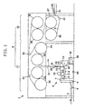
- Fig. 1 shows a warp sizing machine 1.
- the warp sizing machine 1 includes a sizing unit 2 and a cylinder drying unit 3 placed above the sizing unit 2.
- a sheet of multiple warp yarns that is, a warp sheet 4
- a warp sheet 4 is supplied from a warp-sheet feeder (not shown), guided into a size box 8 included in the sizing unit 2 by guide rollers 5, 6, and 7, and immersed into size 10 by an immersion roller 9.
- the warp sheet 4 passes between a first sizing roller 11 and a first squeeze roller 12, which face each other in the vertical direction, and between a second sizing roller 13 and a second squeeze roller 14, which face each other in the horizontal direction.
- the immersion roller 9, the first sizing roller 11, and the second sizing roller 13 are partially immersed in the size 10, and are rotated at a peripheral speed equal to the moving speed of the warp sheet 4.
- the size 10 is contained in the size box 8, and the level of the size 10 is maintained at a predetermined depth by causing the size 10 to overflow.
- a collection box 39 which also contains the size 10 is provided below the size box 8, and the size 10 in the collection box 39 is supplied to the size box 8 through a circulation path by a size circulation pump 40, and is caused to overflow into the collection box 39. Accordingly, the amount of size 10 in the size box 8 is always maintained constant and the level of the size 10 in the size box 8 is maintained at the predetermined depth.
- the collection box 39 is refilled when the level of the size 10 in the collection box 39 falls to or below a predetermined depth.
- the cylinder drying unit 3 includes a first cylinder drying section 17 for primary drying at an upstream location in the moving direction of the warp sheets 4a and 4b and a second cylinder drying section 18 for secondary drying at a downstream location in the moving direction of the warp sheets 4a and 4b.
- the first cylinder drying section 17 includes a first series of drying cylinders 31 and 33 and a second series of drying cylinders 32 and 34 for separately drying the two warp sheets 4a and 4b.
- the two drying cylinders 31 and 32 at the most upstream positions in the two series of drying cylinders are separated from each other in a direction substantially perpendicular to the planes including the warp sheets 4a and 4b, thereby dividing the warp sheet 4 into the two separate warp sheets 4a and 4b.
- the two warp sheets 4a and 4b are recombined together after the primary drying, and accordingly the warp interval returns to the original warp interval. Then, the thus obtained warp sheet 4 is subjected to the secondary drying in the second cylinder drying section 18, where the warp sheet 4 is further dried by coming into contact with drying cylinders 35, 36, 37, and 38. After the primary and secondary drying, the warp sheet 4 is guided by guide rollers 41 and is wrapped around a warp beam (not shown).
- the warp sizing machine 1 is characterized by including a plurality of rods, for example, a first inner rod 15 and a second inner rod 16 corresponding to the two warp sheets 4a and 4b, respectively, in a space between the two warp sheets 4a and 4b moving from the sizing unit 2 to the respective drying cylinders 32 and 31 of the cylinder drying unit 3 (the first cylinder drying section 17).
- the first and the second inner rods 15 and 16 rotate at peripheral speeds lower than the moving speed of the warp sheets 4a and 4b, and are in contact only with the respective warp sheets 4a and 4b.
- the first and the second outer rods 19 and 20 rotate at peripheral speeds lower than the moving speed of the warp sheets 4a and 4b, and are in contact with the respective warp sheets 4a and 4b.
- Fig. 2 shows the positional relationship between the first and the second inner rods 15 and 16 and that between the first and the second outer rods 19 and 20.
- the first and the second inner rods 15 and 16 are disposed as near as possible to the second sizing roller 13 and the second squeeze roller 14 of the sizing unit 2. This is because the warp sheet 4 is preferably divided as quickly as possible after the size starts to dry in view of equalizing the fluff length and reducing the quality variation of the resulting warp sheet 4.
- first and the second inner rods 15 and 16 are positioned such that the relationship L ⁇ (D1 + D2)/2 is satisfied, where D1 is the outer diameter of the first inner rod 15, D2 is the outer diameter of the second inner rod 16, and L is the distance between the axes of the first and the second inner rods 15 and 16 in a direction substantially perpendicular to the moving directions of the warp sheets 4a and 4b, and are disposed as near as possible to the sizing unit 2.
- the first and the second inner rods 15 and 16 are in contact with the respective warp sheets 4a and 4b with a small contact force at positions near the sizing unit 2. Accordingly, fluff binding is performed without causing the first and the second inner rods 15 and 16 to rub the respective warp sheets 4a and 4b hard, and therefore the fluff length is equalized.
- the positions of the first and the second outer rods 19 and 20 and their function will be described in detail below with reference to Fig. 6.
- Fig. 3 shows the supporting structure of the first and the second inner rods 15 and 16 at one end thereof.
- the first and the second inner rods 15 and 16 are both cylindrical, and are connected to hollow shafts 22 with connectors 21 at both ends thereof so that they can rotate relative to oil-impregnated bearing portions included in bearing brackets 23.
- the bearing brackets 23 are attached to a frame 24, and accordingly the first and the second inner rods 15 and 16 are held in place by the frame 24.
- the shafts 22 are connected to rotary joints 26 at ends remote from the first and the second inner rods 15 and 16, and center holes of the shafts 22 and those of the rotary joints 26 function as water passages 25 for a coolant (cooling water).
- the coolant (cooling water) is supplied from a coolant source (cooling water source) into the water passages 25 in the shafts 22 and the rotary joints 26 at one end, enters cooling sections 27 provided in the first and the second inner rods 15 and 16 to cool the first and the second inner rods 15 and 16, and flows out at the other end.
- a coolant source cooling water source
- the coolant (cooling water) circulates in the inner spaces of the first and the second inner rods 15 and 16 as described above, condensation occurs on the peripheral surfaces of the first and the second inner rods 15 and 16, and moisture is added to the size 10 on the peripheral surfaces of the first and the second inner rods 15 and 16.
- the size 10 does not solidify on the peripheral surfaces of the first and the second inner rods 15 and 16, but is removed from the peripheral surfaces by being transferred onto the warp sheets 4a and 4b as the first and the second inner rods 15 and 16 rotate. Accordingly, the size 10 is prevented from accumulating and solidifying on the peripheral surfaces of the first and the second inner rods 15 and 16.
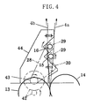
- the rotating directions of the first and the second inner rods 15 and 16 are switched by moving the switching sprocket 30 between the upper and lower positions and changing the manner in which the chain 28 is wrapped around the two sprockets 29.
- the optimum rotating direction is selected depending on the kind of warp, the kind of size, and the operational conditions, such as the moving speed, of the warp sizing machine.
- the rotating directions of the first and the second inner rods 15 and 16 can of course be selected with a selection switch.
- the first and the second outer rods 19 and 20 are placed above the first and the second inner rods 15 and 16 disposed in the space between the warp sheets 4a and 4b. However, one or both of the first and the second outer rods 19 and 20 may also be placed below the first and the second inner rods 15 and 16. The first and the second outer rods 19 and 20 also serve to bend the warp sheets 4a and 4b and reduce the space therebetween.
- the rods 15, 16, 19, and 20 are arranged such that the first and the second inner rods 15 and 16 are in contact only with the respective warp sheets 4a and 4b.
- the warp sheet 4 When the warp sheet 4 is divided into the two separate warp sheets 4a and 4b, vibration of the warp sheets 4a and 4b may occur depending on the kind of warp. In such a case, the warp sheets 4a and 4b vibrate while moving, and there is a risk that the first and the second inner rods 15 and 16 will accidentally come into contact with the warp sheets 4b and 4a, respectively. In this case, however, the first and the second inner rods 15 and 16 are not continuously in contact with the warp sheets 4b and 4a, respectively, but come into contact with them irregularly. Accordingly, the operations and effects of the present invention are maintained.
- the present invention is incorporated in the structure for dividing the warp sheet 4 into the two separate warp sheets 4a and 4b at a position between the sizing unit and the two series of drying cylinders, and the sizing method and the drying method are not limited to those described above.
Landscapes
- Engineering & Computer Science (AREA)
- Textile Engineering (AREA)
- Treatment Of Fiber Materials (AREA)
- Warping, Beaming, Or Leasing (AREA)
Applications Claiming Priority (2)
| Application Number | Priority Date | Filing Date | Title |
|---|---|---|---|
| JP2003354159 | 2003-10-14 | ||
| JP2003354159A JP2005120493A (ja) | 2003-10-14 | 2003-10-14 | 経糸糊付け機 |
Publications (2)
| Publication Number | Publication Date |
|---|---|
| EP1524352A2 true EP1524352A2 (fr) | 2005-04-20 |
| EP1524352A3 EP1524352A3 (fr) | 2005-10-05 |
Family
ID=34373555
Family Applications (1)
| Application Number | Title | Priority Date | Filing Date |
|---|---|---|---|
| EP04023953A Withdrawn EP1524352A3 (fr) | 2003-10-14 | 2004-10-07 | Machine pour l'encollage des fils de chaíne |
Country Status (4)
| Country | Link |
|---|---|
| EP (1) | EP1524352A3 (fr) |
| JP (1) | JP2005120493A (fr) |
| KR (1) | KR20050035830A (fr) |
| CN (1) | CN1607288A (fr) |
Families Citing this family (1)
| Publication number | Priority date | Publication date | Assignee | Title |
|---|---|---|---|---|
| CN210712102U (zh) * | 2019-10-13 | 2020-06-09 | 苏州比达尔创新材料科技有限公司 | 一种纺织纤维均匀上浆装置 |
Family Cites Families (6)
| Publication number | Priority date | Publication date | Assignee | Title |
|---|---|---|---|---|
| US2438084A (en) * | 1946-04-15 | 1948-03-16 | Wood Allison Allen | Yarn smoothing apparatus and method |
| US3732603A (en) * | 1971-11-12 | 1973-05-15 | Burlington Industries Inc | Method and apparatus for laying down the fiber hairiness of textile yarns |
| DE3202923A1 (de) * | 1982-01-29 | 1983-08-11 | Gebrüder Sucker, 4050 Mönchengladbach | Verfahren und vorrichtung zum trocknen einer laufenden fadenschar |
| JPS6042312B2 (ja) * | 1983-02-07 | 1985-09-21 | 桑村繊維株式会社 | 紡績糸の経糸糊付毛羽伏せ方法並びにその装置 |
| JPH0324632Y2 (fr) * | 1986-03-27 | 1991-05-29 | ||
| DE4038368A1 (de) * | 1990-01-19 | 1991-07-25 | Sucker & Franz Mueller Gmbh | Vorrichtung zum trocknen einer fadenschar |
-
2003
- 2003-10-14 JP JP2003354159A patent/JP2005120493A/ja active Pending
-
2004
- 2004-08-06 KR KR1020040062053A patent/KR20050035830A/ko not_active Withdrawn
- 2004-08-10 CN CNA2004100565450A patent/CN1607288A/zh active Pending
- 2004-10-07 EP EP04023953A patent/EP1524352A3/fr not_active Withdrawn
Also Published As
| Publication number | Publication date |
|---|---|
| EP1524352A3 (fr) | 2005-10-05 |
| JP2005120493A (ja) | 2005-05-12 |
| KR20050035830A (ko) | 2005-04-19 |
| CN1607288A (zh) | 2005-04-20 |
Similar Documents
| Publication | Publication Date | Title |
|---|---|---|
| US3861996A (en) | Paper web transfer system carrying the web from forming wire to press section | |
| DE69429941T2 (de) | Verfahren und Modul zum Trocknen sowie ihre Anwendung in Trockenpartien insbesondere von Hochgeschwindigkeitspapiermaschinen | |
| DE69417121T2 (de) | Trockenpartie einer Papiermaschine | |
| EP1524352A2 (fr) | Machine pour l'encollage des fils de chaíne | |
| CA2657627A1 (fr) | Presse a double toile | |
| CN206416653U (zh) | 一种热转移印花机的毛毯张紧装置 | |
| DE3322996C2 (fr) | ||
| FI93876C (fi) | Paperikoneen kuivatusosa, jossa on yksiviiraviennillä varustettuja sylinteriryhmiä | |
| CN109281085A (zh) | 一种浸轧一体染色工艺 | |
| US5785816A (en) | Method for the dewatering of a paper fiber material layer in a double-screen former and apparatus for its execution | |
| EP0302905B1 (fr) | Systeme d'entrainement d'un rouleau-guide de feutre | |
| CN108454230A (zh) | 一种高效纺织加工装置 | |
| KR100504586B1 (ko) | 교정부재를 갖춘 선재 직선교정기 | |
| KR102244089B1 (ko) | 연동형 섬유 건조장치 | |
| CN205775576U (zh) | 一种齿轮齿条多级造纸纤维筛分装置 | |
| US3829359A (en) | Paper making machine having oncetwisted endless felts | |
| CN219525866U (zh) | 一种带有预清洁结构的包纱机 | |
| CN220564800U (zh) | 造纸网毯纤维梳理机用刮料装置 | |
| US2616153A (en) | Felt hardening machine | |
| CN218465144U (zh) | 一种纺织面料加工用除湿装置 | |
| CN212408224U (zh) | 一种具有润滑结构的纺织并轴 | |
| CN214529434U (zh) | 整经机用旋转经轴架 | |
| CN220013064U (zh) | 一种纺纱织品脱水装置 | |
| CN219690065U (zh) | 一种无水印染定型机 | |
| CN117071210A (zh) | 一种用于加弹丝生产的清理装置 |
Legal Events
| Date | Code | Title | Description |
|---|---|---|---|
| PUAI | Public reference made under article 153(3) epc to a published international application that has entered the european phase |
Free format text: ORIGINAL CODE: 0009012 |
|
| AK | Designated contracting states |
Kind code of ref document: A2 Designated state(s): AT BE BG CH CY CZ DE DK EE ES FI FR GB GR HU IE IT LI LU MC NL PL PT RO SE SI SK TR |
|
| AX | Request for extension of the european patent |
Extension state: AL HR LT LV MK |
|
| PUAL | Search report despatched |
Free format text: ORIGINAL CODE: 0009013 |
|
| AK | Designated contracting states |
Kind code of ref document: A3 Designated state(s): AT BE BG CH CY CZ DE DK EE ES FI FR GB GR HU IE IT LI LU MC NL PL PT RO SE SI SK TR |
|
| AX | Request for extension of the european patent |
Extension state: AL HR LT LV MK |
|
| RIC1 | Information provided on ipc code assigned before grant |
Ipc: 7D 06C 15/00 B Ipc: 7D 06B 3/18 A |
|
| AKX | Designation fees paid | ||
| STAA | Information on the status of an ep patent application or granted ep patent |
Free format text: STATUS: THE APPLICATION IS DEEMED TO BE WITHDRAWN |
|
| 18D | Application deemed to be withdrawn |
Effective date: 20060405 |
|
| REG | Reference to a national code |
Ref country code: DE Ref legal event code: 8566 |