EP1524215A1 - Vakuum-Behandlungsanlage für ebene rechteckige bzw. quadratische Substrate - Google Patents
Vakuum-Behandlungsanlage für ebene rechteckige bzw. quadratische Substrate Download PDFInfo
- Publication number
- EP1524215A1 EP1524215A1 EP04019331A EP04019331A EP1524215A1 EP 1524215 A1 EP1524215 A1 EP 1524215A1 EP 04019331 A EP04019331 A EP 04019331A EP 04019331 A EP04019331 A EP 04019331A EP 1524215 A1 EP1524215 A1 EP 1524215A1
- Authority
- EP
- European Patent Office
- Prior art keywords
- vacuum
- chamber
- plant according
- treatment plant
- vacuum treatment
- Prior art date
- Legal status (The legal status is an assumption and is not a legal conclusion. Google has not performed a legal analysis and makes no representation as to the accuracy of the status listed.)
- Granted
Links
- 239000000758 substrate Substances 0.000 title claims abstract description 175
- 238000012545 processing Methods 0.000 title description 2
- 230000007246 mechanism Effects 0.000 claims abstract description 28
- 238000009434 installation Methods 0.000 claims abstract 3
- 238000011282 treatment Methods 0.000 claims description 49
- 230000000712 assembly Effects 0.000 claims description 29
- 238000000429 assembly Methods 0.000 claims description 29
- 238000009489 vacuum treatment Methods 0.000 claims description 23
- 238000012546 transfer Methods 0.000 claims description 17
- 239000007789 gas Substances 0.000 claims description 14
- 125000006850 spacer group Chemical group 0.000 claims description 4
- 230000001360 synchronised effect Effects 0.000 claims description 3
- 230000009471 action Effects 0.000 claims description 2
- 230000000873 masking effect Effects 0.000 claims description 2
- 238000001771 vacuum deposition Methods 0.000 abstract description 2
- 238000000034 method Methods 0.000 description 12
- 238000000576 coating method Methods 0.000 description 9
- 239000000969 carrier Substances 0.000 description 8
- 239000011248 coating agent Substances 0.000 description 7
- 230000009467 reduction Effects 0.000 description 7
- 230000008569 process Effects 0.000 description 6
- 239000002245 particle Substances 0.000 description 5
- 238000005299 abrasion Methods 0.000 description 4
- 238000010276 construction Methods 0.000 description 4
- 239000000463 material Substances 0.000 description 4
- 230000015572 biosynthetic process Effects 0.000 description 3
- 238000011109 contamination Methods 0.000 description 3
- 238000006073 displacement reaction Methods 0.000 description 3
- 239000000428 dust Substances 0.000 description 3
- 238000004901 spalling Methods 0.000 description 3
- 241001295925 Gegenes Species 0.000 description 2
- 230000008859 change Effects 0.000 description 2
- 238000001816 cooling Methods 0.000 description 2
- 230000001186 cumulative effect Effects 0.000 description 2
- 238000013461 design Methods 0.000 description 2
- 238000011161 development Methods 0.000 description 2
- 230000000694 effects Effects 0.000 description 2
- 238000010438 heat treatment Methods 0.000 description 2
- 239000012535 impurity Substances 0.000 description 2
- 238000007789 sealing Methods 0.000 description 2
- 230000007723 transport mechanism Effects 0.000 description 2
- 235000012431 wafers Nutrition 0.000 description 2
- 241001136792 Alle Species 0.000 description 1
- -1 Floppy disks Substances 0.000 description 1
- 206010052128 Glare Diseases 0.000 description 1
- 230000001133 acceleration Effects 0.000 description 1
- 238000009825 accumulation Methods 0.000 description 1
- 230000001154 acute effect Effects 0.000 description 1
- 238000006243 chemical reaction Methods 0.000 description 1
- 239000007795 chemical reaction product Substances 0.000 description 1
- 238000005229 chemical vapour deposition Methods 0.000 description 1
- 238000004140 cleaning Methods 0.000 description 1
- 239000000356 contaminant Substances 0.000 description 1
- 230000001955 cumulated effect Effects 0.000 description 1
- 238000005520 cutting process Methods 0.000 description 1
- 125000004122 cyclic group Chemical group 0.000 description 1
- 238000013500 data storage Methods 0.000 description 1
- 238000000151 deposition Methods 0.000 description 1
- 230000008021 deposition Effects 0.000 description 1
- 238000007599 discharging Methods 0.000 description 1
- 238000009826 distribution Methods 0.000 description 1
- 230000005489 elastic deformation Effects 0.000 description 1
- 230000005611 electricity Effects 0.000 description 1
- 238000005530 etching Methods 0.000 description 1
- 239000011521 glass Substances 0.000 description 1
- 239000011261 inert gas Substances 0.000 description 1
- 239000000203 mixture Substances 0.000 description 1
- 238000010943 off-gassing Methods 0.000 description 1
- 238000005240 physical vapour deposition Methods 0.000 description 1
- 238000009832 plasma treatment Methods 0.000 description 1
- 239000000047 product Substances 0.000 description 1
- 238000005086 pumping Methods 0.000 description 1
- 238000007665 sagging Methods 0.000 description 1
- 239000004065 semiconductor Substances 0.000 description 1
- 238000004544 sputter deposition Methods 0.000 description 1
- 239000000126 substance Substances 0.000 description 1
- 238000004381 surface treatment Methods 0.000 description 1
- 238000012549 training Methods 0.000 description 1
- 238000011144 upstream manufacturing Methods 0.000 description 1
- 238000007738 vacuum evaporation Methods 0.000 description 1
Images




Classifications
-
- C—CHEMISTRY; METALLURGY
- C23—COATING METALLIC MATERIAL; COATING MATERIAL WITH METALLIC MATERIAL; CHEMICAL SURFACE TREATMENT; DIFFUSION TREATMENT OF METALLIC MATERIAL; COATING BY VACUUM EVAPORATION, BY SPUTTERING, BY ION IMPLANTATION OR BY CHEMICAL VAPOUR DEPOSITION, IN GENERAL; INHIBITING CORROSION OF METALLIC MATERIAL OR INCRUSTATION IN GENERAL
- C23C—COATING METALLIC MATERIAL; COATING MATERIAL WITH METALLIC MATERIAL; SURFACE TREATMENT OF METALLIC MATERIAL BY DIFFUSION INTO THE SURFACE, BY CHEMICAL CONVERSION OR SUBSTITUTION; COATING BY VACUUM EVAPORATION, BY SPUTTERING, BY ION IMPLANTATION OR BY CHEMICAL VAPOUR DEPOSITION, IN GENERAL
- C23C14/00—Coating by vacuum evaporation, by sputtering or by ion implantation of the coating forming material
- C23C14/22—Coating by vacuum evaporation, by sputtering or by ion implantation of the coating forming material characterised by the process of coating
- C23C14/56—Apparatus specially adapted for continuous coating; Arrangements for maintaining the vacuum, e.g. vacuum locks
- C23C14/568—Transferring the substrates through a series of coating stations
-
- B—PERFORMING OPERATIONS; TRANSPORTING
- B65—CONVEYING; PACKING; STORING; HANDLING THIN OR FILAMENTARY MATERIAL
- B65G—TRANSPORT OR STORAGE DEVICES, e.g. CONVEYORS FOR LOADING OR TIPPING, SHOP CONVEYOR SYSTEMS OR PNEUMATIC TUBE CONVEYORS
- B65G49/00—Conveying systems characterised by their application for specified purposes not otherwise provided for
- B65G49/05—Conveying systems characterised by their application for specified purposes not otherwise provided for for fragile or damageable materials or articles
- B65G49/06—Conveying systems characterised by their application for specified purposes not otherwise provided for for fragile or damageable materials or articles for fragile sheets, e.g. glass
- B65G49/067—Sheet handling, means, e.g. manipulators, devices for turning or tilting sheet glass
-
- B—PERFORMING OPERATIONS; TRANSPORTING
- B65—CONVEYING; PACKING; STORING; HANDLING THIN OR FILAMENTARY MATERIAL
- B65G—TRANSPORT OR STORAGE DEVICES, e.g. CONVEYORS FOR LOADING OR TIPPING, SHOP CONVEYOR SYSTEMS OR PNEUMATIC TUBE CONVEYORS
- B65G2249/00—Aspects relating to conveying systems for the manufacture of fragile sheets
- B65G2249/02—Controlled or contamination-free environments or clean space conditions
Definitions
- the invention relates to a vacuum treatment plant for flat rectangular or square substrates in an at least substantially vertical position, containing a vacuum chamber with at least two distributed on the circumference of the vacuum chamber chamber side open Treatment chambers, an entry lock, a discharge lock and a rotatable array of substrate holders within the vacuum chamber with a drive mechanism for sequential rotation and the advance and retraction of the substrate holder relative to the treatment chambers.
- each substrate horizontally fed to a lock system therein first lifted by means of a lifting device upwards and then through a pivoting device pivoted in a vertical position, in the it is attached to a substrate holder.
- a lifting device upwards and then through a pivoting device pivoted in a vertical position, in the it is attached to a substrate holder.
- discharging in one second lock system then becomes the order of these steps vice versa.
- This would be true for large rectangular substrates considerable space problems, large lock and chamber volumes as well as long evacuation times and / or high suction rates Lead vacuum pumps.
- the buffer chamber is concentric and arranged with vertical axis a turntable, with which the substrates with their holders and with their main planes, so almost radially aligned with the respective treatment chamber and off retracted this position in the treatment chambers and again be retrieved.
- the turntable has no own substrate holder.
- For the transport of substrate holders are in each treatment chamber and on the turntable separated and separated driven conveyors arranged with rollers for the substrate holder.
- the construction costs and the required drive and Control devices are considerable; In particular, on the Turntable also several independent of each other conveyors be arranged with rollers.
- two buffer chambers with rotatable exchange units for carriers with substrates through two linear transport routes changeable length to connect with each other to the number of To be able to change coating stations.
- the carriers can do this in be transported vertically or slightly inclined position.
- a transport path is provided for a discontinuous transport and has one at each end, adjacent to the buffer chambers Lock chamber with two valves and before and after a loading and an unloading station for the carriers.
- the other transport route is for provided a continuous transport and has at both ends, adjacent to the buffer chambers via valves, one transfer area each for the carriers, each with the substrates.
- Means for a carrier movement transverse to the transport direction within the system are not provided neither on the linear transport paths, nor in the buffer chambers, still in the transfer areas.
- the buffer chambers are only provided with means for heating and cooling.
- the transport device here again serves a rotationally symmetrical passage or buffer chamber with a turntable, on the underside of such a pinion drive with six pinions and a motor to guide, change the direction of displacement and the Radial displacement of the substrate holder is arranged.
- the buffer chamber are - separated by shut-off valves - a lock system and at least three treatment chambers for different Arranged vacuum processes.
- the substrate holders are in radial Retracted longitudinally into the treatment chambers, as a result must have corresponding radial dimensions, so that a fictitious radius around the entire plant has a large diameter, which leads to a correspondingly large footprint.
- the longitudinal displacement and corresponding drives in the treatment chambers are also Therefore, because such treatment chambers in radial Directions can be strung together.
- the invention is therefore based on the object, construction principles and Establish operational procedures leading to a further reduction in the Footprint, the chamber volumes, the evacuation times and to a further simplification of the "handling" of the substrates outside and within the vacuum chamber and still especially one significantly reducing the risk of contamination of the substrates Particles lead to chipped layer packages.
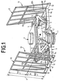
- FIG. 1 is a central drive mechanism 1 with vertical Axle and a coaxial mounting flange 2 for attachment shown at a lower bottom of the vacuum chamber, not shown here.
- This drive mechanism 1 carries in its upper part a Rotatable chamber 3 with square plan, at the corners in total eight booms 4 are attached, which are about oblique struts 5 at support a cylindrical base 6 of the chamber 3, respectively paired together over four radially projecting arms 7 (see see FIG. 2).
- each of the trusses carries at least two prominent rollers 11, which are not as editions for here serve substrates shown and, if necessary, can be driven and / or locked.
- each of the trusses 10 carries an obliquely upward and behind at an angle between 3 and 15 degrees to the vertical aligned frame 12 with longitudinal and transverse struts on Art a framework, the vertical supports 12a on the respective Bracket 9 is supported.
- the two substrate holders 13 shown are thereby in the direction of the arrows 14 opposite and substantially radially to each other movable. It It should be emphasized that only two of the substrate holders 13 are shown. The two remaining substrate holder, in front of and behind the drive mechanism. 1 are arranged, the sake of clarity are not shown. she are also radially movable in opposite directions, and while at right angles to the two arrows 14.
- the frame racks 12 are perforated at numerous points and to a Not shown gas source connected so that the substrates in the Charging position in the manner of a "hovercraft" frictionless and shape-preserving on the respective substrate holder 13, by the rollers 11 led, can be deferred. Thereafter, the gas supply is interrupted, to the gas atmospheres in the individual treatment chambers not to interfere.
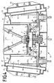
- FIGS. 3 and 4 show the rotation system according to FIGS. 1 and 2 integrated into a vacuum chamber 15 with a vertical axis A-A.
- the Vacuum chamber 15 consists of an inner cup-shaped chamber part 16 with a bottom 17 in which the upper end portion of the drive mechanism 1 is inserted by means of a flange 18 vacuum-tight.
- the vertical support via four anchor struts 19, the effective Length is adjustable via adjusting elements 20. Of these are only the two behind the vertical section plane (E-E in Figure 6) lying adjustment elements 20, which are suspended from radial gussets 21.
- the vacuum chamber 15 further has an outer chamber portion 22 in Shape of a four-sided truncated pyramid with a bottom 23, through the lower end portion 24 of the drive mechanism 1 vacuum-tight passed through.
- the inner and the outer chamber part 16 and 22 are connected by a blanket 25 vacuum-tight.
- the walls of the outer chamber part 22 are in equidistant distribution with four rectangular openings 26 provided, of which here also only two diametrically opposite openings 26 are visible.
- Treatment chambers 27 and 28 placed on, with devices not shown equipped for a wide variety of vacuum processes can be.
- the outer walls 27a and 28a of the treatment chambers 27 and 28 are ribbed 50 for absorbing the forces of atmospheric pressure provided (esp. Figure 7).
- FIG. 5 now shows an enlarged detail of the drive mechanism 1 in its position according to Figure 4. It will be the previous Reference numerals used and updated.
- the drive mechanism 1 has a coaxial, through the bottoms 17 and 23 passing shaft 32, by means of a first vacuum-tight Rotary feedthrough 33 through the upper floor 17 and by means of a second vacuum-tight rotary feedthrough 34 and by a radial bearing 35th is guided through the lower bottom 23 therethrough.
- a group of Connecting piece 36 serves to supply treatment media and if necessary - also for power supply.
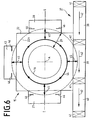
- FIG. 6 now shows a schematic representation of the superimposed one Movements in the circumferential direction and in the radial direction.
- Parallel to the outer chamber part 22, which also in the manner of a truncated cone may be formed according to the dashed circle 22a runs parallel to a tangent to the vacuum chamber 15 a lock row 37, which consists of an entry lock 38 of a transfer chamber 39 and a Discharge lock 40 consists.
- the lock row 37 contains vacuum valves 41 known type.
- the line E-E stands for the vertical cutting plane of the FIGS. 3 and 4.
- the linear stepwise transport direction of the inclined or guided substrates without substrate holder through the lock row 37 is indicated by the row of arrows 42.
- the transfer chamber 39 is located another treatment chamber 43 opposite. Inside the ring-shaped Room 29 are the movement sequences indicated by thick arrows.
- the stepwise rotational movement takes place - from the transfer chamber 39 starting at 90 degrees along the closed arrow line 44.
- At the four stops each immediately before the transfer chamber 39 and the treatment chambers 27, 43 and 28 are by radial Double arrows 45 feed and retraction of the substrates indicated. Of the Feed of the substrates takes place until immediately before shielding frame-shaped Apertures 46, which are in the opening areas of the treatment chambers 27, 43 and 28 are arranged.
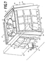
- FIG. 7 now shows a perspective exterior view of a complete one Appendix with the means and the reference numerals according to Figures 1 to 6.
- the entry lock 38 and the discharge lock 40 indicated by dashed lines.
- the inclined entry slot 39a is shown, as well an attached pump nozzle 47 with a gate valve 48th and a cryopump 49.
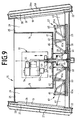
- FIGS. 8 and 9 now show a variant of the article according to FIGS Figures 1 to 7 with the previous reference numerals.
- the difference here is the rotation and feed drive for the Substrate holder 13.
- a rotary and lifting drive 51 is arranged, the one first motor 52 having a reduction gear 53 for generating a Rotary movement and a second motor 54 with a reduction gear 55 for generating a lifting and lowering movement of a common Shaft 56 has.
- Four double trapezoidal arm assemblies 57 are arranged on a turntable 58, which by the shaft 56 in stepwise Rotation is offset.
- the substrate holders 13 are continuous in FIG Lines shown in their retracted positions.
- the T-shaped formation of the members 65 is effected by a connection with further, rotatably attached links 65a, the lower ends of which Pairs of not particularly highlighted sway bearings with the horizontal lower edges of wedge-shaped arms 61 are connected, which are arranged at the lower ends of the substrate holder 13.
- This Movement forced by the angle levers 59 follows synchronously all other trapezoidal handlebar assemblies 57.
- the shaft 56 is by means of a combination 66 of an upper Rotary bearing and a vacuum feedthrough by means of a rotationally fixed circular disc-shaped Support plate 67 through the bottom 17 of the inner Chamber parts 16 passed.
- the lower end of the shaft 56 is axial slidably guided in a lower pivot bearing 68, which in turn in another turntable 69 is mounted, the upwards one cylindrical attachment 70 with openings 71 and a radial Flange 72 carries, on the turntable 58 with the trapezoidal handlebar assemblies 57 is attached.
- the sealing downwards takes place through a stationary support plate 73, the vacuum-tight in the bottom 23 of the outer Chamber parts 22 inserted and below the end of the shaft 56 with a cup-shaped projection 74 is provided for the lowering of the shaft 56.
Landscapes
- Chemical & Material Sciences (AREA)
- Chemical Kinetics & Catalysis (AREA)
- Engineering & Computer Science (AREA)
- Materials Engineering (AREA)
- Mechanical Engineering (AREA)
- Metallurgy (AREA)
- Organic Chemistry (AREA)
- Physical Vapour Deposition (AREA)
- Container, Conveyance, Adherence, Positioning, Of Wafer (AREA)
- Chemical And Physical Treatments For Wood And The Like (AREA)
- Wrappers (AREA)
- Crystals, And After-Treatments Of Crystals (AREA)
- Physical Deposition Of Substances That Are Components Of Semiconductor Devices (AREA)
Abstract
Description
- alle Schwenklager der Lenkeranordnungen unterhalb der waagrechten Mittellinie der Höhe der tragenden Fläche der Substrathalter angeordnet sind,
- der Antriebsmechanismus für jeden Substrathalter paarweise angeordnete Ausleger besitzt, an denen jeweils eine Parallelogramm-Lenkeranordnung hängend angeordnet ist,
- die unteren Schwenklager der Parallelogramm-Lenkeranordnungen jeweils an einem U-förmigen Bügel angeordnet sind, dessen nach außen gerichtete Schenkel mit einer Traverse verbunden sind, die den unteren Abschluß des jeweiligen Substrathalters bildet,
- der Antriebsmechanismus einen Drehteller besitzt, auf den für jeden Substrathalter eine Gruppe von Trapez-Lenkeranordnungen aufgestellt ist,
- der Antriebsmechanismus ein Dreh- und Hubantrieb mit einer konzentrischen Welle ist, durch deren Vertikalbewegung die Trapez-Lenkeranordnungen mit Radialbewegungen auf die Substrathalter zur Einwirkung bringbar sind,
- die Vakuumkammer
- a) ein topfförmiges, rotationssymmetrisches und stationäres inneres Kammerteil mit einer vertikalen Achse und einem ersten Boden besitzt,
- b) ein äußeres, das innere Kammerteil mit Abstand umgebendes Kammerteil besitzt, zwischen denen ein ringförmiger Raum für die Rotation der Substrathalter angeordnet ist, wobei das äußere Kammerteil mit mehreren, in gleichem Winkelabstand angeordnete öffnungen und daran angeschlossene Behandlungskammern versehen ist und einen weiteren Boden besitzt, der stationär und mit Abstand unterhalb des ersten Bodens angeordnet ist,
- c) für die synchrone Radialbewegung der Substrathalter relativ zu den öffnungen der Behandlungskammern mindestens eine Lenkeranordnung aufweist, die um die Achse drehbar zwischen dem ersten Boden und dem zweiten Boden angeordnet ist, und schließlich
- d) eine Schleusenreihe mit einer übergabekammer für die sukzessive Beschickung der Anlage mit rahmenlos geführten Substraten besitzt.
- die lineare, fluchtende Schleusenreihe in tangentialer Ausrichtung zur Vakuumkammer angeordnet ist und eine Eintragsschleuse, eine übergabekammer und eine Austragsschleuse mit zwischengeschalteten Vakuumventilen enthält, wobei die Schleusenreihe einen linearen Transportweg der Substrate vor und nach der Vakuumbehandlung definiert,
- die um die senkrechte Achse drehbaren Substrathalter nach oben hin um einen Winkel zwischen 1 und 20 Grad gegen die Achse geneigt angeordnet sind, insbesondere, wenn die um die senkrechte Achse drehbaren Substrathalter nach oben hin um einen Winkel zwischen 3 und 15 Grad gegen die Achse geneigt angeordnet sind.
- sich für die rahmenlose Führung der Substrate in den Schleusenkammern stationäre Substrathalter befinden, die unter den gleichen Winkeln zur Senkrechten stehen wie die drehbaren Substrathalter (13),
- die Substrathalter an ihren unteren Enden Rollen für die Aufnahme und Weitergabe der Substrate und darüber öffnungen für den Austritt von Gasen zur Ausbildung von Gaskissen zum reibungsfreien Transport der Substrate während ihrer Relativbewegung zum jeweiligen Substrathalter aufweisen,
- die öffnungen der Behandlungskammern in bezug auf die ihnen gegenüber stehenden drehbaren Substrathalter Ränder aufweisen, die in einer zur Ebene der Substrathalter parallelen Ebene liegen,
- die öffnungen der Behandlungskammern mit Blenden zur Maskierung der Substrate während der Behandlung versehen sind,
- die Lenkeranordnungen für den Vorschub der drehbaren Substrathalter ausschließlich Gelenke besitzen, mit denen die Substrathalter ohne Auftreten von linearen Gleitreibungen bewegbar sind,
- die kürzesten und oberen Glieder der Trapez-Lenkeranordnungen in ihrer Mitte weitere Gelenke besitzen, und wenn jeweil zwei in Reihe geschaltete Trapez-Lenkeranordnungen mittels Distanzlenkern derart miteinander verbunden sind, daß die in Reihe geschalteten Trapez-Lenkeranordnungen jeweils gleiche Winkelstellungen einnehmen,
- der Antriebsmechanismus für die Welle in dem inneren, zur Atmosphäre hin offenen Kammerteil angeordnet ist,
- die oberen Glieder der Trapez-Lenkeranordnungen fest angebrachte weitere Lenker besitzen, deren untere Enden über Gelenke mit Auslegern verbunden sind, an deren äußeren Enden die Substrathalter befestigt sind,
- die oberen Glieder und deren Lenker die Form eines "T" aufweisen, insbesondere, wenn
- an der Welle ein Tragflansch angeordnet ist, der über Lenker auf Winkelhebel einwirkt, die auf dem Drehteller gelagert sind und deren einer Schenkel ein Teil der jeweils innersten Trapez-Lenkeranordnungen ist und durch den ein Verschwenken der Trapez-Lenkeranordnungen herbeiführbar ist.
- Figur 1
- eine perspektivische Darstellung des inneren Antriebsmechanismus mit zwei Substratträgern in radial eingezogener Stellung,
- Figur 2
- eine perspektivische Darstellung des inneren Antriebsmechanismus analog Figur 1, jedoch mit zwei Substratträgern in radial ausgefahrener Stellung,
- Figur 3
- einen teilweisen vertikalen Radialschnitt durch eine Vakuumanlage mit einem Antriebsmechanismus in der Stellung nach Figur 1,
- Figur 4
- einen teilweisen vertikalen Radialschnitt durch eine Vakuumanlage mit einem Antriebsmechanismus in der Stellung nach Figur 2,
- Figur 5
- einen vergrößerten Ausschnitt aus dem Antriebsmechanismus gemäß Figur 4,
- Figur 6
- eine schematische Darstellung der überlagerten Bewegungsabläufe in Umfangsrichtung und in radialen Richtungen,
- Figur 7
- eine perspektivische Außenansicht einer vollständigen Anlage mit den Mitteln nach den Figuren 1 bis 6,
- Figur 8
- eine Variante des Gegenstandes nach den Figuren 1 bis 7 mit eingezogenen Substrathaltern analog Figur 3,
- Figur 9
- den Gegenstannd von Figur 8 mit ausgefahreren Substrathaltern analog Figur 4 und
- Figur 10
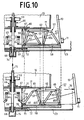
- einen Vergleich von Ausschnitten aus den Figuren 8 und 9,
- 1
- Antriebsmechanismus
- 2
- Montageflansch
- 3
- Kammer
- 4
- Ausleger
- 5
- Schrägstreben
- 6
- Unterbau
- 7
- Ausleger
- 8
- Parallelogramm-Lenkeranordnungen
- 9
- Bügel
- 10
- Traverse
- 11
- Rollen
- 12
- Rahmengestell
- 12a
- Stützen
- 13
- Substrathalter
- 13a
- Stellungen
- 14
- Pfeile
- 15
- Vakuumkammer
- 16
- Kammerteil
- 17
- Boden
- 18
- Flansch
- 19
- Ankerstreben
- 20
- Einstellelemente
- 21
- Knotenbleche
- 22
- Kammerteil
- 22a
- Kreis
- 23
- Boden
- 24
- Endbereich
- 25
- Decke
- 26
- öffnungen
- 27
- Behandlungskammer
- 27a
- Außenwand
- 28
- Behandlungskammer
- 28a
- Außenwand
- 29
- Raum
- 30
- Steuerstangen
- 31
- Schwenklager
- 32
- Welle
- 33
- Drehdurchführung
- 34
- Drehdurchführung
- 35
- Radiallager
- 36
- Anschlußstutzen
- 37
- Schleusenreihe
- 38
- Eintragsschleuse
- 39
- übergabekammer
- 39a
- Eintrittsschlitz
- 40
- Austragsschleuse
- 41
- Vakuumventile
- 42
- Pfeile
- 43
- Behandlungskammer
- 44
- Pfeillinie
- 45
- Doppelpfeile
- 46
- Blenden
- 47
- Pumpstutzen
- 48
- Absperrschieber
- 49
- Kryopumpe
- 50
- Verrippungen
- 51
- Dreh- und Hubantrieb
- 52
- Motor
- 53
- Untersetzungsgetriebe
- 54
- Motor
- 55
- Untersetzungsgetriebe
- 56
- Welle
- 57
- Trapez-Lenkeranordnungen
- 58
- Drehteller
- 59
- Winkelhebel
- 60
- Festlager
- 61
- Ausleger
- 62
- Distanzlenker
- 63
- Tragflansch
- 64
- Lenker
- 65
- Glieder
- 65a
- Lenker
- 66
- Kombination
- 67
- Tragplatte
- 68
- Drehlager
- 69
- Drehscheibe
- 70
- Aufsatz
- 71
- Durchbrechungen
- 72
- Flansch
- 73
- Tragplatte
- 74
- Fortsatz
- 75
- Pfeil
- 76
- Pfeil
- A-A
- Achse
- E-E
- Linie/Schnittebene
- H
- Höhe
- M
- Mittelline
Claims (20)
- Vakuum-Behandlungsanlage für ebene rechteckige bzw. quadratische Substrate in einer zumindest im wesentlichen senkrechten Stellung, enthaltend eine Vakuumkammer (15) mit mindestens zwei auf den Umfang der Vakuumkammer (15) verteilten kammerseitig offenen Behandlungskammern (27, 28, 43), eine Eintragsschleuse (38), eine Austragsschleuse (40) und eine drehbare Anordnung von Substrathaltern (13) innerhalb der Vakuumkammer (15) mit einem Antriebsmechanismus (1, 51) für die sequentielle Rotation und den Vorschub und Rückzug der Substrathalter (13) relativ zu den Behandlungskammern (27, 28, 43), dadurch gekennzeichnet, daß die Substrathalter (13) in ihren unteren Bereichen über Lenkeranordnungen (8, 57) mit dem Antriebsmechanismus (1, 51) verbunden sind und daß zumindest die unteren Schwenklager der Lenkeranordnungen (8, 57) unterhalb einer waagrechten Mittellinie (M) der Höhe (H) der tragenden Fläche der Substrathalter (13) angeordnet sind.
- Vakuum-Behandlungsanlage nach Anspruch 1, dadurch gekennzeichnet, daß alle Schwenklager der Lenkeranordnungen (8, 57) unterhalb der waagrechten Mittellinie (M) der Höhe (H) der tragenden Fläche der Substrathalter (13) angeordnet sind.
- Vakuum-Behandlungsanlage nach Anspruch 1, dadurch gekennzeichnet, daß der Antriebsmechanismus (1) für jeden Substrathalter (13) paarweise angeordnete Ausleger (4) besitzt, an denen jeweils eine Parallelogramm-Lenkeranordnung (8) hängend angeordnet ist.
- Vakuum-Behandlungsanlage nach Anspruch 3, dadurch gekennzeichnet, daß die unteren Schwenklager der Parallelogramm-Lenkeranordnungen jeweils an einem U-förmigen Bügel (9) angeordnet sind, dessen nach außen gerichtete Schenkel (9a) mit einer Traverse (10) verbunden sind, die den unteren Abschluß des jeweiligen Substrathalters (13) bildet.
- Vakuum-Behandlungsanlage nach den Ansprüchen 1 und 2, dadurch gekennzeichnet, daß der Antriebsmechanismus (51) einen Drehteller (58) besitzt, auf den für jeden Substrathalter (13) eine Gruppe von Trapez-Lenkeranordnungen (57) aufgestellt ist.
- Vakuum-Behandlungsanlage nach Anspruch 5, dadurch gekennzeichnet, daß der Antriebsmechanismus (51) ein Dreh- und Hubantrieb mit einer konzentrischen Welle (56) ist, durch deren Vertikalbewegung die Trapez-Lenkeranordnungen (57) mit Radialbewegungen auf die Substrathalter (13) zur Einwirkung bringbar sind.
- Vakuum-Behandlungsanlage nach mindestens einem der Ansprüche 1 bis 6, dadurch gekennzeichnet, daß die Vakuumkammer (15)a) ein topfförmiges, rotationssymmetrisches und stationäres inneres Kammerteil (16) mit einer vertikalen Achse (A-A) und einem ersten Boden (17) besitzt,b) ein äußeres, das innere Kammerteil (16) mit Abstand umgebendes Kammerteil (22) besitzt, zwischen denen ein ringförmiger Raum (29) für die Rotation der Substrathalter (13) angeordnet ist, wobei das äußere Kammerteil (22) mit mehreren, in gleichem Winkelabstand angeordnete öffnungen (26) und daran angeschlossene Behandlungskammern (27, 28, 43) versehen ist und einen weiteren Boden (23) besitzt, der stationär und mit Abstand unterhalb des ersten Bodens (17) angeordnet ist,c) für die synchrone Radialbewegung der Substrathalter (13) relativ zu den öffnungen (26) der Behandlungskammern (27, 28, 43) mindestens eine Lenkeranordnung (8, 57) aufweist, die um die Achse (A-A) drehbar zwischen dem ersten Boden (17) und dem zweiten Boden (23) angeordnet ist, und schließlichd) eine Schleusenreihe (37) mit einer übergabekammer (39) für die sukzessive Beschickung der Anlage mit rahmenlos geführten Substraten.
- Vakuum-Behandlungsanlage nach mindestens einem der Ansprüche 1 bis 7, dadurch gekennzeichnet, daß
die lineare, fluchtende Schleusenreihe (37) in tangentialer Ausrichtung zur Vakuumkammer (15) angeordnet ist und eine Eintragsschleuse (38), eine übergabekammer (39) und eine Austragsschleuse (40) mit zwischengeschalteten Vakuumventilen (41) enthält, wobei die Schleusenreihe (37) einen linearen Transportweg der Substrate vor und nach der Vakuumbehandlung definiert. - Vakuum-Behandlungsanlage nach mindestens einem der Ansprüche 1 bis 8, dadurch gekennzeichnet, daß die um die senkrechte Achse (A-A) drehbaren Substrathalter (13) nach oben hin um einen Winkel zwischen 1 und 20 Grad gegen die Achse (A-A) geneigt angeordnet sind.
- Vakuum-Behandlungsanlage nach Anspruch 9, dadurch gekennzeichnet, daß die um die senkrechte Achse (A-A) drehbaren Substrathalter (13) nach oben hin um einen Winkel zwischen 3 und 15 Grad gegen die Achse (A-A) geneigt angeordnet sind.
- Vakuum-Behandlungsanlage nach mindestens einem der Ansprüche 1 bis 10, dadurch gekennzeichnet, daß sich für die rahmenlose Führung der Substrate in den Schleusenkammern (38, 40) stationäre Substrathalter befinden, die unter den gleichen Winkeln zur Senkrechten stehen wie die drehbaren Substrathalter (13).
- Vakuum-Behandlungsanlage nach mindestens einem der Ansprüche 1 bis 11, dadurch gekennzeichnet, daß die Substrathalter (13) an ihren unteren Enden Rollen (11) für die Aufnahme und Weitergabe der Substrate und darüber öffnungen für den Austritt von Gasen zur Ausbildung von Gaskissen zum reibungsfreien Transport der Substrate während ihrer Relativbewegung zum jeweiligen Substrathalter (13) aufweisen.
- Vakuum-Behandlungsanlage nach mindestens einem der Ansprüche 1 bis 12, dadurch gekennzeichnet, daß die öffnungen (26) der Behandlungskammern (27, 28, 43) in bezug auf die ihnen gegenüber stehenden drehbaren Substrathalter (13) Ränder aufweisen, die in einer zur Ebene der Substrathalter (13) parallelen Ebene liegen.
- Vakuum-Behandlungsanlage nach Anspruch 13 , dadurch gekennzeichnet, daß die öffnungen (26) der Behandlungskammern (27, 28, 43) mit Blenden (46) zur Maskierung der Substrate während der Behandlung versehen sind.
- Vakuum-Behandlungsanlage nach mindestens einem der Ansprüche 1 bis 14, dadurch gekennzeichnet, daß die Lenkeranordnungen (8, 57) für den Vorschub der drehbaren Substrathalter (13) ausschließlich Gelenke besitzen, mit denen die Substrathalter (13) ohne Auftreten von linearen Gleitreibungen bewegbar sind.
- Vakuum-Behandlungsanlage nach Anspruch 5, dadurch gekennzeichnet, daß die kürzesten und oberen Glieder (65) der Trapez-Lenkeranordnungen (57) in ihrer Mitte weitere Gelenke besitzen, und daß jeweil zwei in Reihe geschaltete Trapez-Lenkeranordnungen (57) mittels Distanzlenkern (62) derart miteinander verbunden sind, daß die in Reihe geschalteten Trapez-Lenkeranordnungen (57) jeweils gleiche Winkelstellungen einnehmen.
- Vakuum-Behandlungsanlage nach mindestens einem der Ansprüche 5 bis 7, dadurch gekennzeichnet, daß der Antriebsmechanismus (51) für die Welle (56) in dem inneren, zur Atmosphäre hin offenen Kammerteil (16) angeordnet ist.
- Vakuum-Behandlungsanlage nach Anspruch 16, dadurch gekennzeichnet, daß die oberen Glieder (65) der Trapez-Lenkeranordnungen (57) fest angebrachte weitere Lenker (65a) besitzen, deren untere Enden über Gelenke mit Auslegern (61) verbunden sind, an deren äußeren Enden die Substrathalter (13) befestigt sind.
- Vakuum-Behandlungsanlage nach Anspruch 18, dadurch gekennzeichnet, daß die oberen Glieder (65) und deren Lenker (65a) die Form eines "T" aufweisen.
- Vakuum-Behandlungsanlage nach mindestens einem der Ansprüche 16 bis 19, dadurch gekennzeichnet, daß an der Welle (56) ein Tragflansch (63) angeordnet ist, der über Lenker (64) auf Winkelhebel (59) einwirkt, die auf dem Drehteller (58) gelagert sind und deren einer Schenkel ein Teil der jeweils innersten Trapez-Lenkeranordnungen (57) ist und durch den ein Verschwenken der Trapez-Lenkeranordnungen (57) herbeiführbar ist.
Priority Applications (1)
| Application Number | Priority Date | Filing Date | Title |
|---|---|---|---|
| PL04019331T PL1524215T3 (pl) | 2003-10-17 | 2004-08-14 | Instalacja próżniowa do obróbki płaskich prostokątnych względnie kwadratowych podłoży |
Applications Claiming Priority (2)
| Application Number | Priority Date | Filing Date | Title |
|---|---|---|---|
| DE10348281 | 2003-10-17 | ||
| DE10348281A DE10348281B4 (de) | 2003-10-17 | 2003-10-17 | Vakuum-Behandlungsanlage für ebene rechteckige oder quadratische Substrate |
Publications (2)
| Publication Number | Publication Date |
|---|---|
| EP1524215A1 true EP1524215A1 (de) | 2005-04-20 |
| EP1524215B1 EP1524215B1 (de) | 2006-08-02 |
Family
ID=34353448
Family Applications (1)
| Application Number | Title | Priority Date | Filing Date |
|---|---|---|---|
| EP04019331A Expired - Lifetime EP1524215B1 (de) | 2003-10-17 | 2004-08-14 | Vakuum-Behandlungsanlage für ebene rechteckige bzw. quadratische Substrate |
Country Status (9)
| Country | Link |
|---|---|
| US (1) | US20050081791A1 (de) |
| EP (1) | EP1524215B1 (de) |
| JP (1) | JP3997223B2 (de) |
| KR (1) | KR100689652B1 (de) |
| CN (1) | CN100381605C (de) |
| AT (1) | ATE334920T1 (de) |
| DE (2) | DE10348281B4 (de) |
| PL (1) | PL1524215T3 (de) |
| TW (1) | TWI250220B (de) |
Cited By (2)
| Publication number | Priority date | Publication date | Assignee | Title |
|---|---|---|---|---|
| WO2009003552A3 (de) * | 2007-05-09 | 2009-05-28 | Leybold Optics Gmbh | Behandlungssystem für flache substrate |
| EP3217421A1 (de) * | 2014-06-24 | 2017-09-13 | EV Group E. Thallner GmbH | Vorrichtung zur oberflächenbehandlung von substraten |
Families Citing this family (5)
| Publication number | Priority date | Publication date | Assignee | Title |
|---|---|---|---|---|
| ATE518970T1 (de) | 2008-02-01 | 2011-08-15 | Applied Materials Inc | Doppelbeschichtungsvorrichtung mit verbesserter trennplatte |
| DE112009002468B4 (de) * | 2008-11-14 | 2020-01-02 | Ulvac, Inc. | Dünnschicht-Niederschlagsvorrichtung, organische EL-Element-Herstellungsvorrichtung und organische Dünnschicht-Niederschlagsverfahren |
| DE102008059794B3 (de) * | 2008-12-01 | 2010-04-01 | Grenzebach Maschinenbau Gmbh | Verfahren und Vorrichtung zur Umkehr der Beschickung von Sputter-Beschichtungsanlagen in Reinräumen, sowie Computerprogramm zur Durchführung des Verfahrens und maschinenlesbarer Träger mit dem Programmcode |
| DE102010043883A1 (de) * | 2010-11-12 | 2012-05-16 | Von Ardenne Anlagentechnik Gmbh | Beschichtungsverfahren und Beschichtungsanlage |
| CN103147053B (zh) * | 2012-12-14 | 2015-04-22 | 广东志成冠军集团有限公司 | 多功能连续式磁控溅射镀膜装置 |
Citations (6)
| Publication number | Priority date | Publication date | Assignee | Title |
|---|---|---|---|---|
| BE648039A (de) * | ||||
| FR2307770A1 (fr) * | 1975-04-17 | 1976-11-12 | Saint Gobain | Dispositif automatique pour servir des feuilles de verre sur une machine et simultanement evacuer les feuilles travaillees |
| GB2169872A (en) * | 1985-01-17 | 1986-07-23 | Andrew Marc Edwards | Materials handling machine |
| EP0665193A2 (de) * | 1994-01-11 | 1995-08-02 | Intevac, Inc. | System zum Behandeln und zum Handhaben von Substraten für Flachdisplays |
| JP2001253536A (ja) * | 2000-03-09 | 2001-09-18 | Hirata Corp | 基板移載ロボット装置 |
| US20020078892A1 (en) * | 2000-12-27 | 2002-06-27 | Nobuyuki Takahashi | Substrate processing device and through-chamber |
Family Cites Families (4)
| Publication number | Priority date | Publication date | Assignee | Title |
|---|---|---|---|---|
| JP2948842B2 (ja) * | 1989-11-24 | 1999-09-13 | 日本真空技術株式会社 | インライン型cvd装置 |
| CH691376A5 (de) * | 1995-10-17 | 2001-07-13 | Unaxis Balzers Ag | Vakuumanlage zur Oberflächenbearbeitung von Werkstücken. |
| JP3794964B2 (ja) * | 2002-02-06 | 2006-07-12 | 三菱重工業株式会社 | クラスタ型真空処理装置 |
| ATE343220T1 (de) * | 2004-05-28 | 2006-11-15 | Applied Films Gmbh & Co Kg | Antriebsmechanismus für eine vakuum- behandlungsanlage |
-
2003
- 2003-10-17 DE DE10348281A patent/DE10348281B4/de not_active Expired - Fee Related
-
2004
- 2004-03-26 TW TW093108293A patent/TWI250220B/zh not_active IP Right Cessation
- 2004-08-14 DE DE502004001084T patent/DE502004001084D1/de not_active Expired - Lifetime
- 2004-08-14 EP EP04019331A patent/EP1524215B1/de not_active Expired - Lifetime
- 2004-08-14 PL PL04019331T patent/PL1524215T3/pl unknown
- 2004-08-14 AT AT04019331T patent/ATE334920T1/de not_active IP Right Cessation
- 2004-09-02 US US10/932,563 patent/US20050081791A1/en not_active Abandoned
- 2004-09-17 JP JP2004272073A patent/JP3997223B2/ja not_active Expired - Fee Related
- 2004-10-14 KR KR1020040082166A patent/KR100689652B1/ko not_active Expired - Fee Related
- 2004-10-15 CN CNB2004100856831A patent/CN100381605C/zh not_active Expired - Fee Related
Patent Citations (6)
| Publication number | Priority date | Publication date | Assignee | Title |
|---|---|---|---|---|
| BE648039A (de) * | ||||
| FR2307770A1 (fr) * | 1975-04-17 | 1976-11-12 | Saint Gobain | Dispositif automatique pour servir des feuilles de verre sur une machine et simultanement evacuer les feuilles travaillees |
| GB2169872A (en) * | 1985-01-17 | 1986-07-23 | Andrew Marc Edwards | Materials handling machine |
| EP0665193A2 (de) * | 1994-01-11 | 1995-08-02 | Intevac, Inc. | System zum Behandeln und zum Handhaben von Substraten für Flachdisplays |
| JP2001253536A (ja) * | 2000-03-09 | 2001-09-18 | Hirata Corp | 基板移載ロボット装置 |
| US20020078892A1 (en) * | 2000-12-27 | 2002-06-27 | Nobuyuki Takahashi | Substrate processing device and through-chamber |
Non-Patent Citations (1)
| Title |
|---|
| PATENT ABSTRACTS OF JAPAN vol. 2000, no. 26 1 July 2002 (2002-07-01) * |
Cited By (2)
| Publication number | Priority date | Publication date | Assignee | Title |
|---|---|---|---|---|
| WO2009003552A3 (de) * | 2007-05-09 | 2009-05-28 | Leybold Optics Gmbh | Behandlungssystem für flache substrate |
| EP3217421A1 (de) * | 2014-06-24 | 2017-09-13 | EV Group E. Thallner GmbH | Vorrichtung zur oberflächenbehandlung von substraten |
Also Published As
| Publication number | Publication date |
|---|---|
| JP2005120468A (ja) | 2005-05-12 |
| JP3997223B2 (ja) | 2007-10-24 |
| ATE334920T1 (de) | 2006-08-15 |
| DE10348281B4 (de) | 2007-06-06 |
| TW200514864A (en) | 2005-05-01 |
| CN1609269A (zh) | 2005-04-27 |
| TWI250220B (en) | 2006-03-01 |
| US20050081791A1 (en) | 2005-04-21 |
| EP1524215B1 (de) | 2006-08-02 |
| KR20050037360A (ko) | 2005-04-21 |
| DE502004001084D1 (de) | 2006-09-14 |
| KR100689652B1 (ko) | 2007-03-08 |
| CN100381605C (zh) | 2008-04-16 |
| PL1524215T3 (pl) | 2006-11-30 |
| DE10348281A1 (de) | 2005-05-19 |
Similar Documents
| Publication | Publication Date | Title |
|---|---|---|
| EP0354294B1 (de) | Vorrichtung nach dem Karussell-Prinzip zum Beschichten von Substraten | |
| EP0291690B1 (de) | Vorrichtung zum Ein-und Ausschleusen von Werkstücken in eine Beschichtungskammer | |
| EP0312694B1 (de) | Vorrichtung nach dem Karussell-Prinzip zum Beschichten von Substraten | |
| DE3854270T2 (de) | System zur chemischen abscheidung aus der dampfphase. | |
| DE4210110C2 (de) | Halbleitereinrichtung-Herstellungsvorrichtung und Verfahren zum Herstellen einer Halbleitereinrichtung | |
| DE69023633T2 (de) | Kathodenzerstäubungsgerät und kathodenzerstäubungsanlage. | |
| DE69307445T2 (de) | Schichtbildende Vorrichtung | |
| EP0396951B1 (de) | Halte- und Transportvorrichtung für eine Scheibe | |
| CH691376A5 (de) | Vakuumanlage zur Oberflächenbearbeitung von Werkstücken. | |
| EP0518109B1 (de) | Vakuumbehandlungsanlage | |
| EP1571234B1 (de) | Verfahren für den Betrieb einer Inline-Beschichtungsanlage | |
| WO2009117983A1 (de) | Verfahren und vorrichtung zur fixierung und den weitertransport stossempfindlicher platten in sputter - beschickungsanlagen | |
| DE3702775A1 (de) | Vorrichtung zum quasi-kontinuierlichen behandeln von substraten | |
| EP0905275B1 (de) | Vorrichtung zum Beschichten eines im wesentlichen flachen scheibenförmigen Substrats | |
| EP1617456B1 (de) | Antriebsmechanismus für eine Vakuum-Behandlungsanlage | |
| DE10348281B4 (de) | Vakuum-Behandlungsanlage für ebene rechteckige oder quadratische Substrate | |
| WO2010122152A1 (de) | Transporteinrichtung mit einem auslenkbaren dichtrahmen | |
| DE10319379A1 (de) | Vorrichtung zum Transportieren eines flachen Substrats in einer Vakuumkammer | |
| EP1042788B1 (de) | Vakuumbehandlungsanlage | |
| DE202012102431U1 (de) | Vorrichtung zur Gasseparation in einer Anlage zur Vakuumbehandlung | |
| EP0389820A1 (de) | Vorrichtung zum Ein- und Ausschleusen eines Werkstücks in eine Vakuumkammer | |
| CH691377A5 (de) | Kammeranordnung für den Transport von Werkstücken und deren Verwendung. | |
| DE4235674C2 (de) | Kammer für den Transport von Werkstücken in Vakuumatmosphäre, Kammerkombination und Verfahren zum Transportieren eines Werkstückes | |
| DE102011083139A1 (de) | Substratbehandlungsverfahren und Substratbehandlungsanlage | |
| DE1796098A1 (de) | Anlage zur Herstellung von Oberflaechenaufdampfungen vorzugsweise auf Glasscheiben |
Legal Events
| Date | Code | Title | Description |
|---|---|---|---|
| PUAI | Public reference made under article 153(3) epc to a published international application that has entered the european phase |
Free format text: ORIGINAL CODE: 0009012 |
|
| AK | Designated contracting states |
Kind code of ref document: A1 Designated state(s): AT BE BG CH CY CZ DE DK EE ES FI FR GB GR HU IE IT LI LU MC NL PL PT RO SE SI SK TR |
|
| AX | Request for extension of the european patent |
Extension state: AL HR LT LV MK |
|
| 17P | Request for examination filed |
Effective date: 20050226 |
|
| AKX | Designation fees paid |
Designated state(s): AT BE BG CH CY CZ DE DK EE ES FI FR GB GR HU IE IT LI LU MC NL PL PT RO SE SI SK TR |
|
| GRAP | Despatch of communication of intention to grant a patent |
Free format text: ORIGINAL CODE: EPIDOSNIGR1 |
|
| GRAS | Grant fee paid |
Free format text: ORIGINAL CODE: EPIDOSNIGR3 |
|
| GRAA | (expected) grant |
Free format text: ORIGINAL CODE: 0009210 |
|
| AK | Designated contracting states |
Kind code of ref document: B1 Designated state(s): AT BE BG CH CY CZ DE DK EE ES FI FR GB GR HU IE IT LI LU MC NL PL PT RO SE SI SK TR |
|
| PG25 | Lapsed in a contracting state [announced via postgrant information from national office to epo] |
Ref country code: IT Free format text: LAPSE BECAUSE OF FAILURE TO SUBMIT A TRANSLATION OF THE DESCRIPTION OR TO PAY THE FEE WITHIN THE PRESCRIBED TIME-LIMIT;WARNING: LAPSES OF ITALIAN PATENTS WITH EFFECTIVE DATE BEFORE 2007 MAY HAVE OCCURRED AT ANY TIME BEFORE 2007. THE CORRECT EFFECTIVE DATE MAY BE DIFFERENT FROM THE ONE RECORDED. Effective date: 20060802 Ref country code: FI Free format text: LAPSE BECAUSE OF FAILURE TO SUBMIT A TRANSLATION OF THE DESCRIPTION OR TO PAY THE FEE WITHIN THE PRESCRIBED TIME-LIMIT Effective date: 20060802 Ref country code: SI Free format text: LAPSE BECAUSE OF FAILURE TO SUBMIT A TRANSLATION OF THE DESCRIPTION OR TO PAY THE FEE WITHIN THE PRESCRIBED TIME-LIMIT Effective date: 20060802 Ref country code: GB Free format text: LAPSE BECAUSE OF FAILURE TO SUBMIT A TRANSLATION OF THE DESCRIPTION OR TO PAY THE FEE WITHIN THE PRESCRIBED TIME-LIMIT Effective date: 20060802 Ref country code: IE Free format text: LAPSE BECAUSE OF FAILURE TO SUBMIT A TRANSLATION OF THE DESCRIPTION OR TO PAY THE FEE WITHIN THE PRESCRIBED TIME-LIMIT Effective date: 20060802 Ref country code: SK Free format text: LAPSE BECAUSE OF FAILURE TO SUBMIT A TRANSLATION OF THE DESCRIPTION OR TO PAY THE FEE WITHIN THE PRESCRIBED TIME-LIMIT Effective date: 20060802 Ref country code: RO Free format text: LAPSE BECAUSE OF FAILURE TO SUBMIT A TRANSLATION OF THE DESCRIPTION OR TO PAY THE FEE WITHIN THE PRESCRIBED TIME-LIMIT Effective date: 20060802 |
|
| REG | Reference to a national code |
Ref country code: GB Ref legal event code: FG4D Free format text: NOT ENGLISH |
|
| PG25 | Lapsed in a contracting state [announced via postgrant information from national office to epo] |
Ref country code: MC Free format text: LAPSE BECAUSE OF NON-PAYMENT OF DUE FEES Effective date: 20060831 |
|
| REG | Reference to a national code |
Ref country code: CH Ref legal event code: NV Representative=s name: KEMENY AG PATENTANWALTBUERO Ref country code: CH Ref legal event code: EP |
|
| REG | Reference to a national code |
Ref country code: IE Ref legal event code: FG4D Free format text: LANGUAGE OF EP DOCUMENT: GERMAN |
|
| REF | Corresponds to: |
Ref document number: 502004001084 Country of ref document: DE Date of ref document: 20060914 Kind code of ref document: P |
|
| PG25 | Lapsed in a contracting state [announced via postgrant information from national office to epo] |
Ref country code: SE Free format text: LAPSE BECAUSE OF FAILURE TO SUBMIT A TRANSLATION OF THE DESCRIPTION OR TO PAY THE FEE WITHIN THE PRESCRIBED TIME-LIMIT Effective date: 20061102 Ref country code: BG Free format text: LAPSE BECAUSE OF FAILURE TO SUBMIT A TRANSLATION OF THE DESCRIPTION OR TO PAY THE FEE WITHIN THE PRESCRIBED TIME-LIMIT Effective date: 20061102 Ref country code: DK Free format text: LAPSE BECAUSE OF FAILURE TO SUBMIT A TRANSLATION OF THE DESCRIPTION OR TO PAY THE FEE WITHIN THE PRESCRIBED TIME-LIMIT Effective date: 20061102 |
|
| PG25 | Lapsed in a contracting state [announced via postgrant information from national office to epo] |
Ref country code: ES Free format text: LAPSE BECAUSE OF FAILURE TO SUBMIT A TRANSLATION OF THE DESCRIPTION OR TO PAY THE FEE WITHIN THE PRESCRIBED TIME-LIMIT Effective date: 20061113 |
|
| PG25 | Lapsed in a contracting state [announced via postgrant information from national office to epo] |
Ref country code: PT Free format text: LAPSE BECAUSE OF FAILURE TO SUBMIT A TRANSLATION OF THE DESCRIPTION OR TO PAY THE FEE WITHIN THE PRESCRIBED TIME-LIMIT Effective date: 20070102 |
|
| RAP2 | Party data changed (patent owner data changed or rights of a patent transferred) |
Owner name: APPLIED MATERIALS GMBH & CO. KG |
|
| ET | Fr: translation filed | ||
| GBV | Gb: ep patent (uk) treated as always having been void in accordance with gb section 77(7)/1977 [no translation filed] |
Effective date: 20060802 |
|
| NLT1 | Nl: modifications of names registered in virtue of documents presented to the patent office pursuant to art. 16 a, paragraph 1 |
Owner name: APPLIED MATERIALS GMBH & CO. KG |
|
| NLT2 | Nl: modifications (of names), taken from the european patent patent bulletin |
Owner name: APPLIED MATERIALS GMBH & CO. KG Effective date: 20070103 |
|
| REG | Reference to a national code |
Ref country code: CH Ref legal event code: PFA Owner name: APPLIED MATERIALS GMBH & CO. KG Free format text: APPLIED FILMS GMBH & CO. KG#SIEMENSSTRASSE 100#63755 ALZENAU (DE) -TRANSFER TO- APPLIED MATERIALS GMBH & CO. KG#SIEMENSSTRASSE 100#63755 ALZENAU (DE) |
|
| REG | Reference to a national code |
Ref country code: IE Ref legal event code: FD4D |
|
| REG | Reference to a national code |
Ref country code: FR Ref legal event code: CD |
|
| PLBE | No opposition filed within time limit |
Free format text: ORIGINAL CODE: 0009261 |
|
| STAA | Information on the status of an ep patent application or granted ep patent |
Free format text: STATUS: NO OPPOSITION FILED WITHIN TIME LIMIT |
|
| 26N | No opposition filed |
Effective date: 20070503 |
|
| PG25 | Lapsed in a contracting state [announced via postgrant information from national office to epo] |
Ref country code: AT Free format text: LAPSE BECAUSE OF NON-PAYMENT OF DUE FEES Effective date: 20060814 |
|
| BECN | Be: change of holder's name |
Owner name: *APPLIED MATERIALS G.M.B.H. & CO. K.G. Effective date: 20060802 |
|
| PG25 | Lapsed in a contracting state [announced via postgrant information from national office to epo] |
Ref country code: GR Free format text: LAPSE BECAUSE OF FAILURE TO SUBMIT A TRANSLATION OF THE DESCRIPTION OR TO PAY THE FEE WITHIN THE PRESCRIBED TIME-LIMIT Effective date: 20061103 |
|
| PG25 | Lapsed in a contracting state [announced via postgrant information from national office to epo] |
Ref country code: EE Free format text: LAPSE BECAUSE OF FAILURE TO SUBMIT A TRANSLATION OF THE DESCRIPTION OR TO PAY THE FEE WITHIN THE PRESCRIBED TIME-LIMIT Effective date: 20060802 |
|
| PG25 | Lapsed in a contracting state [announced via postgrant information from national office to epo] |
Ref country code: LU Free format text: LAPSE BECAUSE OF NON-PAYMENT OF DUE FEES Effective date: 20060814 Ref country code: TR Free format text: LAPSE BECAUSE OF FAILURE TO SUBMIT A TRANSLATION OF THE DESCRIPTION OR TO PAY THE FEE WITHIN THE PRESCRIBED TIME-LIMIT Effective date: 20060802 Ref country code: HU Free format text: LAPSE BECAUSE OF FAILURE TO SUBMIT A TRANSLATION OF THE DESCRIPTION OR TO PAY THE FEE WITHIN THE PRESCRIBED TIME-LIMIT Effective date: 20070203 |
|
| PGFP | Annual fee paid to national office [announced via postgrant information from national office to epo] |
Ref country code: CH Payment date: 20080717 Year of fee payment: 5 Ref country code: NL Payment date: 20080718 Year of fee payment: 5 |
|
| PG25 | Lapsed in a contracting state [announced via postgrant information from national office to epo] |
Ref country code: CY Free format text: LAPSE BECAUSE OF FAILURE TO SUBMIT A TRANSLATION OF THE DESCRIPTION OR TO PAY THE FEE WITHIN THE PRESCRIBED TIME-LIMIT Effective date: 20060802 |
|
| PGFP | Annual fee paid to national office [announced via postgrant information from national office to epo] |
Ref country code: CZ Payment date: 20080728 Year of fee payment: 5 Ref country code: FR Payment date: 20080714 Year of fee payment: 5 Ref country code: PL Payment date: 20080805 Year of fee payment: 5 |
|
| PGFP | Annual fee paid to national office [announced via postgrant information from national office to epo] |
Ref country code: BE Payment date: 20080801 Year of fee payment: 5 |
|
| PGFP | Annual fee paid to national office [announced via postgrant information from national office to epo] |
Ref country code: DE Payment date: 20090821 Year of fee payment: 6 |
|
| BERE | Be: lapsed |
Owner name: *APPLIED MATERIALS G.M.B.H. & CO. K.G. Effective date: 20090831 |
|
| REG | Reference to a national code |
Ref country code: CH Ref legal event code: PL Ref country code: NL Ref legal event code: V1 Effective date: 20100301 |
|
| PG25 | Lapsed in a contracting state [announced via postgrant information from national office to epo] |
Ref country code: CZ Free format text: LAPSE BECAUSE OF NON-PAYMENT OF DUE FEES Effective date: 20090814 Ref country code: CH Free format text: LAPSE BECAUSE OF NON-PAYMENT OF DUE FEES Effective date: 20090831 Ref country code: LI Free format text: LAPSE BECAUSE OF NON-PAYMENT OF DUE FEES Effective date: 20090831 |
|
| REG | Reference to a national code |
Ref country code: FR Ref legal event code: ST Effective date: 20100430 |
|
| PG25 | Lapsed in a contracting state [announced via postgrant information from national office to epo] |
Ref country code: BE Free format text: LAPSE BECAUSE OF NON-PAYMENT OF DUE FEES Effective date: 20090831 |
|
| PG25 | Lapsed in a contracting state [announced via postgrant information from national office to epo] |
Ref country code: FR Free format text: LAPSE BECAUSE OF NON-PAYMENT OF DUE FEES Effective date: 20090831 Ref country code: NL Free format text: LAPSE BECAUSE OF NON-PAYMENT OF DUE FEES Effective date: 20100301 |
|
| PG25 | Lapsed in a contracting state [announced via postgrant information from national office to epo] |
Ref country code: PL Free format text: LAPSE BECAUSE OF NON-PAYMENT OF DUE FEES Effective date: 20090814 |
|
| REG | Reference to a national code |
Ref country code: DE Ref legal event code: R119 Ref document number: 502004001084 Country of ref document: DE Effective date: 20110301 |
|
| REG | Reference to a national code |
Ref country code: PL Ref legal event code: LAPE |
|
| PG25 | Lapsed in a contracting state [announced via postgrant information from national office to epo] |
Ref country code: DE Free format text: LAPSE BECAUSE OF NON-PAYMENT OF DUE FEES Effective date: 20110301 |