EP1524133B1 - Sender für ein Reifenzustandsüberwachungsgerät - Google Patents
Sender für ein Reifenzustandsüberwachungsgerät Download PDFInfo
- Publication number
- EP1524133B1 EP1524133B1 EP04005319A EP04005319A EP1524133B1 EP 1524133 B1 EP1524133 B1 EP 1524133B1 EP 04005319 A EP04005319 A EP 04005319A EP 04005319 A EP04005319 A EP 04005319A EP 1524133 B1 EP1524133 B1 EP 1524133B1
- Authority
- EP
- European Patent Office
- Prior art keywords
- transmission
- transmitter
- vehicle
- tire
- transmission power
- Prior art date
- Legal status (The legal status is an assumption and is not a legal conclusion. Google has not performed a legal analysis and makes no representation as to the accuracy of the status listed.)
- Expired - Lifetime
Links
- 238000012544 monitoring process Methods 0.000 title claims description 18
- 230000005540 biological transmission Effects 0.000 claims description 206
- 238000001514 detection method Methods 0.000 claims description 35
- 230000001133 acceleration Effects 0.000 claims description 31
- 238000000034 method Methods 0.000 claims description 6
- 229910052751 metal Inorganic materials 0.000 description 8
- 239000002184 metal Substances 0.000 description 8
- 239000011324 bead Substances 0.000 description 5
- 230000005856 abnormality Effects 0.000 description 4
- 238000005259 measurement Methods 0.000 description 4
- 238000013459 approach Methods 0.000 description 3
- 230000002238 attenuated effect Effects 0.000 description 3
- 238000010586 diagram Methods 0.000 description 3
- XEEYBQQBJWHFJM-UHFFFAOYSA-N Iron Chemical compound [Fe] XEEYBQQBJWHFJM-UHFFFAOYSA-N 0.000 description 2
- 230000005611 electricity Effects 0.000 description 2
- 230000000737 periodic effect Effects 0.000 description 2
- 229910052782 aluminium Inorganic materials 0.000 description 1
- XAGFODPZIPBFFR-UHFFFAOYSA-N aluminium Chemical compound [Al] XAGFODPZIPBFFR-UHFFFAOYSA-N 0.000 description 1
- 230000001276 controlling effect Effects 0.000 description 1
- 229910052742 iron Inorganic materials 0.000 description 1
- 238000012986 modification Methods 0.000 description 1
- 230000004048 modification Effects 0.000 description 1
- 238000012545 processing Methods 0.000 description 1
- 230000001105 regulatory effect Effects 0.000 description 1
- 230000003014 reinforcing effect Effects 0.000 description 1
Images

Classifications
-
- B—PERFORMING OPERATIONS; TRANSPORTING
- B60—VEHICLES IN GENERAL
- B60C—VEHICLE TYRES; TYRE INFLATION; TYRE CHANGING; CONNECTING VALVES TO INFLATABLE ELASTIC BODIES IN GENERAL; DEVICES OR ARRANGEMENTS RELATED TO TYRES
- B60C23/00—Devices for measuring, signalling, controlling, or distributing tyre pressure or temperature, specially adapted for mounting on vehicles; Arrangement of tyre inflating devices on vehicles, e.g. of pumps or of tanks; Tyre cooling arrangements
- B60C23/02—Signalling devices actuated by tyre pressure
- B60C23/04—Signalling devices actuated by tyre pressure mounted on the wheel or tyre
- B60C23/0408—Signalling devices actuated by tyre pressure mounted on the wheel or tyre transmitting the signals by non-mechanical means from the wheel or tyre to a vehicle body mounted receiver
Definitions
- the present invention relates to a transmitter of a tire condition monitoring apparatus. More particularly, the present invention pertains to a transmitter for a wireless tire condition monitoring apparatus that permits a driver in a vehicle passenger compartment to check conditions of tires, such as the air pressure.
- Wireless tire condition monitoring apparatuses that allow a driver in a vehicle passenger compartment to check the conditions of vehicle tires have been proposed.
- Japanese Laid-Open Patent Publication No. 2001-174357 discloses such an apparatus.
- the apparatus of the publication includes transmitters and a receiver. Each transmitter is located in the wheel of one of the tires and the receiver is located in the body frame of the vehicle. Each transmitter detects the conditions, such as air pressure and the temperature of the associated tire, and wirelessly transmits the detected information.
- the receiver receives data wirelessly transmitted by the transmitters with an antenna and displays the conditions of the tires, for example, on a display located in front of the driver's seat.
- Each transmitter is accommodated in a case provided in the corresponding tire valve.
- the tire valve is fitted in a valve hole of the corresponding wheel. Accordingly, the case, which accommodates the transmitter, is located in the corresponding tire.
- the wheels are formed of metal, such as aluminum and iron.
- Metal bead wire is embedded in sidewalls of each tire for reinforcing the tire.
- the transmitter is provided in a tire of a vehicle, and comprises a running state detection device for detecting a running state of the vehicle; a transmission circuit, wherein the transmission circuit generates a transmission signal containing data representing a condition of the tire and outputs the transmission signal; an antenna for wirelessly transmitting the transmission signal; and a controller that changes transmission intervals according to a detection result of the running state detection device.
- the present invention provides a transmitter of a tire condition monitoring apparatus.
- the transmitter is provided in a tire of a vehicle.
- the transmitter has a running state detection device, a transmission circuit, an antenna and a controller.
- the running state detection device detects the running state of the vehicle.
- the transmission circuit generates a transmission signal containing data representing a condition of the tire and outputs the transmission signal.
- the antenna wirelessly transmits the transmission signal.
- the controller changes the transmission power of the transmission circuit according to the detection result of the running state detection device.
- the present invention also provides a transmitter of a tire condition monitoring apparatus.
- the transmitter is attached to a vehicle wheel to be located inside a tire.
- the transmitter has a detection device, a transmission circuit, an antenna and a controller.
- the detection device detects that the transmitter is attached to the wheel.
- the transmission circuit generates a transmission signal containing data representing a condition of the tire and outputs the transmission signal.
- the antenna wirelessly transmits the transmission signal.
- the controller changes a transmission power of the transmission circuit according to a detection result of the detection device.
- the present invention also provides a transmitter of a tire condition monitoring apparatus.
- the transmitter is provided in a tire of a vehicle and wirelessly transmits data representing a condition of the tire.
- the transmitter has a transmission circuit, an antenna and a controller.
- the transmission circuit generates a transmission signal containing data representing a condition of the tire and outputs the transmission signal.
- the antenna wirelessly transmits the transmission signal.
- the controller detects whether the antenna is detuned.
- the controller changes a transmission power of the transmission circuit according to a detection result.
- the present invention also provides a method for controlling a transmission power.
- the method is applied to a transmitter of a tire condition monitoring apparatus.
- the transmitter is provided in a tire of a vehicle and includes a transmission circuit and an antenna.
- the transmission circuit generates a transmission signal containing data representing a condition of the tire and outputs the transmission signal.
- the antenna wirelessly transmits the transmission signal.
- the method including detecting a running state of the vehicle with a running state detection device; and changing a transmission power of the transmission circuit according to a detection result of the running state detection device.
- Transmitters 30 of a tire condition monitoring apparatus 1 will now be described with reference to the drawings.
- the apparatus 1 is used in a vehicle such as an automobile.
- the tire condition monitoring apparatus 1 includes the transmitters 30 and a receiver 40.
- the number of the transmitters 30 is four.
- Each transmitter 30 is located in one of the tires 20 of a vehicle 10.
- the receiver 40 is located on a body frame 11 of the vehicle 10.
- Each transmitter 30 is located in the corresponding tire 20 and is fixed, for example, to a wheel 21 of the tire 20. Each transmitter 30 measures the condition of the corresponding tire 20, that is, the pressure of the tire 20. The transmitter 30 then wirelessly transmits data containing air pressure data.
- the receiver 40 is located at a predetermined position on the body frame 11 and is activated by electricity of a battery (not shown) of the vehicle 10.
- a reception antenna 41 is connected to the receiver 40 with a cable 42. The receiver 40 receives data transmitted by the transmitters 30 through the reception antenna 41.
- a display 50 is located in the view of the driver of the vehicle 10, for example, in the passenger compartment.
- the display 50 is connected to the receiver 40 with a cable 43.
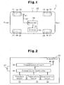
- each transmitter 30 includes a transmission controller 31, which is a microcomputer.
- the controller 31 includes, for example, a central processing unit (CPU), a read only memory (ROM), and a random access memory (RAM).
- a unique ID code is registered in an internal memory, for example, the ROM, of the controller 31. The ID code is used to distinguish the associated transmitter 30 from the other three transmitters 30.
- Each transmitter 30 includes a pressure sensor 32, a temperature sensor 33, and an acceleration sensor 34.
- the tire pressure sensor 32 measures the air pressure in the interior of the associated tire 20 and provides the controller 31 with pressure data, which is obtained from the measurement.
- the temperature sensor 33 measures the temperature in the interior of the associated tire 20 and provides the transmission controller 31 with temperature data, which is obtained from the measurement.
- the acceleration sensor 34 detects a centrifugal acceleration that acts on the acceleration sensor 34 as the tire 20 rotates.
- the centrifugal acceleration is a parameter that correlates with the speed of the vehicle. Specifically, when detecting a centrifugal acceleration that is equal to or greater than a predetermined reference value, each acceleration sensor 34 outputs data representing the running state of the vehicle 10 to the transmission controller 31.
- the tires 20 rotate.
- the transmitter 30 attached to the wheel 21 of the corresponding tire 20, which applies acceleration to the associated acceleration sensor 34.
- centrifugal acceleration applied to each acceleration sensor 34 reaches the predetermined reference value.
- the acceleration sensor 34 sends data representing that the vehicle 10 is moving to the transmission controller 31.
- Each transmission controller 31 sends the air pressure data, the temperature data, and the registered ID code to a transmission circuit 35.
- the transmission circuit 35 encodes and modulates the data sent from the transmission controller 31, thereby generating a transmission signal.
- the transmission antenna 36 transmits the transmission signal as a wireless radio wave.
- Each transmitter 30 is provided with a battery 37. The transmitter 30 is driven by electricity of the battery 37.
- the transmission controller 31 of each transmitter 30 controls the pressure sensor 32 and the temperature sensor 33 to perform measurement at predetermined time intervals (for example, every fifteen seconds). Also, the transmission controller 31 controls the transmission circuit 35 to perform periodic transmission every time the pressure sensor 32 completes a predetermined number of (e.g., 4 cycles of) measurements. Further, when detecting an abnormality of the pressure in the tire 20 or of the temperature in the tire 20, the controller 31 causes the transmission circuit 35 to perform transmission irrespective of timing of the periodic transmission.
- the timing of transmission of the transmitters 30 are regulated such that each transmitter 30 performs transmission at a timing different from those of the other transmitters 30. Therefore, two or more of the transmitters 30 do not perform transmission simultaneously.
- each acceleration sensor 34 detects a centrifugal acceleration that is equal to or greater than the predetermined reference value
- the acceleration sensor 34 outputs data representing the running state of the vehicle 10 to the transmission controller 31.
- the transmission controller 31 determines that the transmitter 30 has been installed in the wheel 21 of a tire 20 and has started being used.
- the transmission controller 31 then a signal requesting a change in the transmission power to the transmission circuit 35.
- the transmission circuit 35 changes the transmission power (first transmission power) to a greater transmission power (second transmission power).
- the transmission power of the transmission circuit 35 is changed to a value greater than the current transmission power.
- the transmission controller 31 increases the transmission power of the transmission circuit 35 based on the start of use of the transmitter 30.
- each transmitter 30 is provided in the wheel 21 of the corresponding tire 20, data that is wirelessly transmitted by the transmitter 30 is received by the receiver 40.
- the receiver 40 includes a reception controller 44 and a reception circuit 45.
- the reception controller 44 processes data received with the reception antenna 41.
- the reception controller 44 which is, for example, a microcomputer, includes a CPU, a ROM, and a RAM.
- the reception circuit 45 receives data transmitted by the transmitters 30 through the reception antenna 41.
- the reception circuit 45 demodulates and decodes the received data and sends the data to the reception controller 44.
- the reception controller 44 Based on the received data, the reception controller 44 obtains the internal pressure and the temperature of the tire 20 that are associated with the transmitter 30 that is the source of the received data. The reception controller 44 also causes the display 50 to show data regarding the air pressure and the temperature. Particularly, when there is an abnormality in the internal pressure or the temperature of the tire 20, the reception controller 44 displays warning on the display 50.
- the receiver 40 is activated when a key switch (not shown) of the vehicle 10 is turned on.
- This embodiment has the following advantages.
- Each transmission controller 31 may determine whether the speed of the vehicle 10 is equal to or greater than a predetermined value based on a detection result of the associated acceleration sensor 34. In this case, the transmission controller 31 increases the transmission power of the transmission circuit 35 when the vehicle speed is equal to or greater than the reference value. Specifically, when the speed of the vehicle 10 is equal to or greater than the reference value, the transmission controller 31 changes the transmission power of the transmission circuit 35 from the current transmission power (the first transmission power) to a greater transmission power (the second transmission power).
- the illustrated embodiment may be modified that, when the speed of the vehicle is determined to be less than a reference value based on a detection result of the acceleration sensor 34, the transmission controller 31 changes the transmission power of the transmission circuit 35 to the first transmission power, which is smaller than the second transmission power.
- the transmission controller 31 changes the transmission power of the transmission circuit 35 from the current transmission power (the first transmission power) to a greater transmission power (the second transmission power).
- the transmission controller 31 changes the transmission power of the transmission circuit 35 according to the speed of the vehicle 10.
- the transmission controller 31 increases the transmission power of the transmission circuit 35 for a greater value of the speed of the vehicle. This reduces the power consumption of the battery 37. As a result, the life of the battery 37 is extended.
- the transmission antenna 36 is detuned by influence of the metal used in the wheel 21 and the bead wire in the tire 20.
- the transmission circuit 35 which includes a tuning circuit, is also detuned. This reduces the transmission power of the transmission circuit 35.
- the transmission controller 31 may be configured to change the transmission power of the transmission circuit 35 when the transmission antenna 36 is detuned. That is, when the transmission antenna 36 is detuned, the transmission controller 31 makes the transmission power of the transmission circuit 35 greater than the transmission power when the transmission antenna 36 is not detuned. In this configuration, the acceleration sensor 34 may be omitted.
- a mechanical switch for example, a push button switch 70
- the push button switch 70 is switched to different states when the transmitter 30 is attached to the wheel 21 and when the transmitter 30 is detached from the wheel 21.
- the push button switch 70 is provided such that the push button switch 70 is pressed by a drop center portion 22 of the wheel 21 when a tire valve 80 is attached to the wheel 21.
- the transmission controller 31 changes the transmission power of the transmission circuit 35. That is, when the transmitter 30 is attached to the wheel 21, the transmission controller 31 makes the transmission power of the transmission circuit 35 greater than the transmission power when the transmitter 30 is detached from the wheel 21.
- the transmitter 30 shown in Fig. 2 may be provided with the push button switch 70 shown in Fig. 4. In this case, only when the push button switch 70 is pressed down, that is, when the transmitter 30 is attached to the wheel 21, the transmission power is switched based on a signal from the acceleration sensor 34. When the push button switch 70 is not pressed down, that is, when the transmitter 30 is not attached to the wheel 21, the transmission power is maintained to a low level (first transmission power).
- the acceleration sensor 34 may be replaced by another type of detection means that converts the approach of metal into an electrical change.
- a magnetoresistance (MR) element may be used.
- the transmission controller 31 changes the transmission power of the transmission circuit 35 to an appropriate transmission power.
- the transmission controller 31 may be configured to change the transmission power of the transmission circuit 35 to an appropriate transmission power based on whether metal approaches the element. This configuration also extends the life of the battery 37.
- the acceleration sensor 34 may be replaced by other types of driving detection means such as a rotation sensor that detects rotation of the tire 20 and an angular acceleration sensor that detects an angular acceleration of the tire 20. These types of_sensors are capable of detecting whether the vehicle 10 is moving. This modification has the same advantages as the illustrated embodiment.
- the reference value of the acceleration sensor 34 may be changed to a value that indicates that the vehicle 10 is not moving. For example, the reference value may be changed to zero.
- the abnormality When there is an abnormality in the pressure or the temperature of the tire 20, the abnormality may be indicated by a sound.
- a speaker that is mounted on the vehicle 10 in advance may be used as an informing device.
- Air pressure data and temperature data transmitted by the transmitter 30 may indicate the values of the air pressure and the temperature or whether the air pressure and the temperature are within permissible ranges.
- the temperature sensor 33 may be omitted. This reduces the costs of the transmitter 30 of the tire condition monitoring apparatus 1.
- the present invention may be applied to two-wheeled vehicles, such as bicycles and motor cycles, multi-wheeled busses, multi-wheeled trailers and industrial vehicles having the tires 20 (for example, a forklift).
- two-wheeled vehicles such as bicycles and motor cycles, multi-wheeled busses, multi-wheeled trailers and industrial vehicles having the tires 20 (for example, a forklift).
- the present invention is applied to a trailer, the receiver 40 and the display 50 are provided in the tractor.
Landscapes
- Engineering & Computer Science (AREA)
- Mechanical Engineering (AREA)
- Arrangements For Transmission Of Measured Signals (AREA)
- Measuring Fluid Pressure (AREA)
Claims (12)
- Sender einer Reifenzustandsüberwachungsvorrichtung, der in einem Fahrzeugreifen vorgesehen ist, mit:einer Betriebszustandsdetektionseinrichtung zum Detektieren des Betriebszustands des Fahrzeugs;einer Sendeschaltung, die ein Sendesignal erzeugt, das einen Zustand des Reifens wiedergebende Daten enthält, und das Sendesignal ausgibt;einer Antenne zum drahtlosen Senden des Sendesignals, undeinem Controller, der die Sendeleistung der Sendeschaltung dem Detektionsergebnis der Betriebszustandsdetektionseinrichtung gemäß ändert.
- Sender nach Anspruch 1, dadurch gekennzeichnet, daß die Betriebszustandsdetektionseinrichtung einen Beschleunigungssensor aufweist.
- Sender nach Anspruch 1 oder 2, dadurch gekennzeichnet, daß der Controller anhand eines Detektionsergebnisses der Betriebszustandsdetektionseinrichtung feststellt, ob sich das Fahrzeug bewegt, wobei der Controller, wenn festgestellt wird, daß sich das Fahrzeug bewegt, die Sendeleistung der Sendeschaltung gegenüber einer Sendeleistung erhöht, bei der festgestellt wird, daß sich das Fahrzeug nicht bewegt.
- Sender nach Anspruch 1 oder 2, dadurch gekennzeichnet, daß die Betriebszustandsdetektionseinrichtung einen Parameter detektiert, der mit einer Geschwindigkeit des Fahrzeugs korreliert, wobei der Controller die Sendeleistung der Sendeschaltung der Geschwindigkeit des Fahrzeugs gemäß ändert.
- Sender nach Anspruch 4, dadurch gekennzeichnet, daß der Controller die Sendeleistung der Sendeschaltung bei einem höheren Wert der Fahrzeuggeschwindigkeit erhöht.
- Sender nach Anspruch 4, dadurch gekennzeichnet, daß der Controller, wenn die Geschwindigkeit größer oder gleich einem Referenzwert ist, die Sendeleistung der Sendeschaltung gegenüber der Sendeleistung erhöht, bei der die Geschwindigkeit des Fahrzeugs kleiner als der Referenzwert ist.
- Sender einer Reifenzustandsüberwachungsvorrichtung, der an einer im Inneren eines Reifens anzuordnenden Fahrzeugfelge angebracht ist, mit:einer Detektionseinrichtung zum Detektieren, daß der Sender an der Felge angebracht ist;einer Sendeschaltung, die ein Sendesignal erzeugt, das einen Zustand des Reifens wiedergebende Daten enthält, und das Sendesignal ausgibt;einer Antenne zum drahtlosen Senden des Sendesignals, undeinem Controller, der eine Sendeleistung der Sendeschaltung einem Detektionsergebnis der Detektionseinrichtung gemäß ändert.
- Sender nach Anspruch 7, dadurch gekennzeichnet, daß die Detektionseinrichtung ein Schalter ist, der abhängig davon, ob der Sender an der Felge angebracht oder von der Felge abgenommen ist, in unterschiedliche Zustände geschaltet wird.
- Sender nach Anspruch 7 oder 8, dadurch gekennzeichnet, daß der Controller die Sendeleistung der Sendeschaltung bei an der Felge angebrachtem Sender gegenüber der Sendeleistung bei von der Felge abgenommenem Sender erhöht.
- Sender einer Reifenzustandsüberwachungsvorrichtung, der in einem Fahrzeugreifen vorgesehen ist und drahtlos einen Zustand des Reifens wiedergebende Daten sendet, mit:einer Sendeschaltung, die ein Sendesignal erzeugt, das einen Zustand des Reifens wiedergebende Daten enthält, und das Sendesignal ausgibt;einer Antenne zum drahtlosen Senden des Sendesignals, undeinem Controller zum Detektieren, ob die Antenne verstimmt ist, wobei der Controller eine Sendeleistung der Sendeschaltung einem Detektionsergebnis gemäß ändert.
- Sender nach Anspruch 10, dadurch gekennzeichnet, daß der Controller, wenn festgestellt wird, daß die Sendeantenne verstimmt ist, die Sendeleistung der Sendeschaltung gegenüber der Sendeleistung erhöht, bei der festgestellt wird, daß die Sendeantenne nicht verstimmt ist.
- Verfahren zur Steuerung einer Sendeleistung, wobei das Verfahren auf einen Sender einer Reifenzustandsüberwachungsvorrichtung angewandt wird, der in einem Fahrzeugreifen vorgesehen ist und eine Sendeschaltung sowie eine Antenne aufweist, wobei die Sendeschaltung ein Sendesignal erzeugt, das einen Zustand des Reifens wiedergebende Daten enthält, und das Sendesignal ausgibt, und wobei die Antenne das Sendesignal drahtlos sendet,
wobei der Sender einen Betriebszustand des Fahrzeugs mit einer Betriebszustandsdetektionseinrichtung detektiert, und
eine Sendeleistung der Sendeschaltung einem Detektionsergebnis der Betriebszustandsdetektionseinrichtung gemäß ändert.
Applications Claiming Priority (2)
| Application Number | Priority Date | Filing Date | Title |
|---|---|---|---|
| JP2003354108 | 2003-10-14 | ||
| JP2003354108A JP2005119370A (ja) | 2003-10-14 | 2003-10-14 | タイヤ状態監視装置の送信機 |
Publications (2)
| Publication Number | Publication Date |
|---|---|
| EP1524133A1 EP1524133A1 (de) | 2005-04-20 |
| EP1524133B1 true EP1524133B1 (de) | 2006-08-23 |
Family
ID=34373552
Family Applications (1)
| Application Number | Title | Priority Date | Filing Date |
|---|---|---|---|
| EP04005319A Expired - Lifetime EP1524133B1 (de) | 2003-10-14 | 2004-03-05 | Sender für ein Reifenzustandsüberwachungsgerät |
Country Status (4)
| Country | Link |
|---|---|
| US (1) | US7212105B2 (de) |
| EP (1) | EP1524133B1 (de) |
| JP (1) | JP2005119370A (de) |
| DE (1) | DE602004002058T2 (de) |
Families Citing this family (29)
| Publication number | Priority date | Publication date | Assignee | Title |
|---|---|---|---|---|
| JP2005329856A (ja) * | 2004-05-21 | 2005-12-02 | Nec Electronics Corp | 監視装置、送受信システム及びその制御方法 |
| JP4289561B2 (ja) * | 2004-12-24 | 2009-07-01 | 横浜ゴム株式会社 | 車両の異常検出方法及びその装置並びにそのセンサユニット |
| JP2006327324A (ja) * | 2005-05-24 | 2006-12-07 | Fuji Heavy Ind Ltd | タイヤ状態監視装置 |
| FI122392B (fi) * | 2005-07-14 | 2011-12-30 | Secure Oy W | Ajoneuvon pyörien tarkkailujärjestelmä ja langaton mittausmoduuli |
| JP2007107987A (ja) * | 2005-10-13 | 2007-04-26 | Pacific Ind Co Ltd | タイヤ状態監視装置 |
| JP4856423B2 (ja) * | 2005-12-27 | 2012-01-18 | 太平洋工業株式会社 | タイヤ情報通信システム |
| TWI326644B (en) * | 2006-01-30 | 2010-07-01 | Sanyo Electric Co | Tire pressure monitoring system and tire pressure monitoring device |
| JP4721225B2 (ja) | 2006-03-24 | 2011-07-13 | 太平洋工業株式会社 | タイヤ状態監視装置及びその製造方法 |
| JP4921017B2 (ja) | 2006-03-31 | 2012-04-18 | 太平洋工業株式会社 | データ通信システム |
| JP2007287019A (ja) | 2006-04-19 | 2007-11-01 | Pacific Ind Co Ltd | タイヤ監視用無線回路及びタイヤ監視システム |
| JP2007290664A (ja) | 2006-04-27 | 2007-11-08 | Pacific Ind Co Ltd | タイヤ圧検出側受信回路及びタイヤ監視システム |
| FR2906063B1 (fr) * | 2006-09-19 | 2011-08-05 | Renault Sas | Systeme de gestion de capteurs embarques, piece de vehicule et vehicule correspondants |
| JP5019839B2 (ja) | 2006-10-04 | 2012-09-05 | 株式会社ブリヂストン | タイヤ情報管理システム |
| JP2008230536A (ja) * | 2007-03-23 | 2008-10-02 | Pacific Ind Co Ltd | 無線機搭載車両 |
| US8676245B2 (en) * | 2007-03-30 | 2014-03-18 | Motorola Solutions, Inc. | System and method for controlling the transmission power of a node |
| US8098146B2 (en) * | 2007-10-26 | 2012-01-17 | Measurement Ltd. | Tire pressure monitoring system using wireless network |
| DE102008008237B4 (de) * | 2008-02-08 | 2021-06-02 | Volkswagen Ag | Verfahren und System zur Erfassung der Drehbewegung eines Fahrzeugrades |
| DE102008021466A1 (de) * | 2008-04-29 | 2009-11-12 | Beru Ag | Verfahren, System und Systemkomponenten zur drahtlosen Reifendrucküberwachung |
| DE102008021469A1 (de) * | 2008-04-29 | 2009-11-05 | Beru Ag | Verfahren, System und Systemkomponenten zur drahtlosen Reifendrucküberwachung |
| IT1397584B1 (it) | 2009-12-18 | 2013-01-16 | Eltek Spa | Dispositivo di monitoraggio di una ruota di un veicolo e relativo metodo di comunicazione. |
| FR2955414B1 (fr) * | 2010-01-15 | 2012-02-03 | Johnson Controls Tech Co | Procede d'echange de signaux entre un capteur de pression de pneu et une unite centrale equipant un vehicule automobile. |
| CN103487640A (zh) * | 2013-09-22 | 2014-01-01 | 浙江大学 | 基于分布式网络的企业用电设备的电流监测方法 |
| JP2015143049A (ja) * | 2014-01-31 | 2015-08-06 | 太平洋工業株式会社 | 走行検出装置 |
| CN105539029B (zh) * | 2015-12-21 | 2017-11-07 | 同致电子科技(厦门)有限公司 | 一种胎压监测模块自动调节发射功率的方法 |
| GB2547937B (en) * | 2016-03-04 | 2018-12-19 | Continental Automotive Gmbh | Wheel unit, system for transmitting data from a wheel unit, and method for transmitting data from a wheel unit |
| JP6618455B2 (ja) * | 2016-11-28 | 2019-12-11 | 日立オートモティブシステムズ株式会社 | 電子制御装置、車載システム、および電源制御方法 |
| DE102019104741B4 (de) * | 2019-02-25 | 2021-07-22 | Sick Ag | Sensorvorrichtung und Überwachungssystem |
| EP3888955B1 (de) * | 2019-08-29 | 2025-08-27 | Pacific Industrial Co., Ltd. | Sender, empfänger und sende-/empfangssystem |
| FR3120687B1 (fr) * | 2021-03-09 | 2023-01-27 | Continental Automotive | Détection d’une anomalie de géométrie d’une roue de véhicule |
Family Cites Families (9)
| Publication number | Priority date | Publication date | Assignee | Title |
|---|---|---|---|---|
| DE3703128A1 (de) * | 1987-02-03 | 1988-08-11 | Continental Gummi Werke Ag | Ueberwachungsverfahren und -vorrichtung fuer dynamisch beanspruchte gummiartikel |
| US5109213A (en) * | 1991-07-05 | 1992-04-28 | Williams John J | Tire pressure monitor |
| US5838229A (en) * | 1995-07-18 | 1998-11-17 | Schrader-Bridgeport International, Inc. | Remote tire pressure monitoring system employing coded tire identification and radio frequency transmission and enabling recalibration upon tire rotation or replacement |
| DE19534616B4 (de) * | 1995-09-18 | 2007-01-11 | Alpha-Beta Electronics Ag | Reifendruck-Überwachungseinrichtung |
| EP1110764B1 (de) * | 1999-12-20 | 2005-12-07 | TRW Automotive U.S. LLC | Vorrichtung und Verfahren zur Überprüfung des Betriebszustandes eines Fahrzeugsreifen |
| JP2001174357A (ja) | 1999-12-22 | 2001-06-29 | Pacific Ind Co Ltd | タイヤ空気圧センサー |
| US6570462B2 (en) * | 2000-11-08 | 2003-05-27 | Research In Motion Limited | Adaptive tuning device and method utilizing a surface acoustic wave device for tuning a wireless communication device |
| JP2003237328A (ja) * | 2002-02-19 | 2003-08-27 | Pacific Ind Co Ltd | タイヤ状態監視装置の送信機及びタイヤ状態監視装置 |
| US6691567B2 (en) * | 2002-03-01 | 2004-02-17 | Lear Corporation | System and method for tire pressure monitoring including automatic tire location recognition |
-
2003
- 2003-10-14 JP JP2003354108A patent/JP2005119370A/ja active Pending
-
2004
- 2004-03-05 DE DE602004002058T patent/DE602004002058T2/de not_active Expired - Fee Related
- 2004-03-05 EP EP04005319A patent/EP1524133B1/de not_active Expired - Lifetime
- 2004-03-17 US US10/802,189 patent/US7212105B2/en not_active Expired - Fee Related
Also Published As
| Publication number | Publication date |
|---|---|
| US20050078002A1 (en) | 2005-04-14 |
| DE602004002058D1 (de) | 2006-10-05 |
| EP1524133A1 (de) | 2005-04-20 |
| US7212105B2 (en) | 2007-05-01 |
| DE602004002058T2 (de) | 2007-03-01 |
| JP2005119370A (ja) | 2005-05-12 |
Similar Documents
| Publication | Publication Date | Title |
|---|---|---|
| EP1524133B1 (de) | Sender für ein Reifenzustandsüberwachungsgerät | |
| US6963274B2 (en) | Transmitter of tire condition monitoring apparatus and tire condition monitoring apparatus | |
| US6983649B2 (en) | Tire condition monitoring apparatus | |
| US20040172179A1 (en) | Transmitter of tire condition monitoring apparatus and tire condition monitoring apparatus | |
| US6885292B2 (en) | Tire condition monitoring apparatus | |
| EP1325820B1 (de) | Vorrichtung und Verfahren zur Reifenzustandsüberwachung | |
| US7253726B2 (en) | Tire condition monitoring apparatus, transmitter, and receiver | |
| US20030107481A1 (en) | Tire condition monitoring apparatus and method | |
| EP1468847B1 (de) | Reifenzustandsüberwachungsgerät | |
| EP1428693B1 (de) | Transponder für Reifenzustandsüberwachungsgerät | |
| EP1486357A1 (de) | Transmitter of tire condition monitoring apparatus and tire condition monitoring apparatus | |
| US7116217B2 (en) | Transmitter and receiver for tire condition monitoring apparatus | |
| EP1433626A2 (de) | Reifenzustandüberwachungsgerät | |
| EP1419906B1 (de) | Übertragungsverfahren für einen Sender und Verarbeitungsverfahren für einen Empfänger | |
| US8296006B2 (en) | Tire pressure monitoring device |
Legal Events
| Date | Code | Title | Description |
|---|---|---|---|
| PUAI | Public reference made under article 153(3) epc to a published international application that has entered the european phase |
Free format text: ORIGINAL CODE: 0009012 |
|
| AK | Designated contracting states |
Kind code of ref document: A1 Designated state(s): AT BE BG CH CY CZ DE DK EE ES FI FR GB GR HU IE IT LI LU MC NL PL PT RO SE SI SK TR |
|
| AX | Request for extension of the european patent |
Extension state: AL LT LV MK |
|
| 17P | Request for examination filed |
Effective date: 20050401 |
|
| GRAP | Despatch of communication of intention to grant a patent |
Free format text: ORIGINAL CODE: EPIDOSNIGR1 |
|
| AKX | Designation fees paid |
Designated state(s): DE FR GB |
|
| RIN1 | Information on inventor provided before grant (corrected) |
Inventor name: YOUICHI, OKUBO C/O PACIFIC INDUSTRIAL CO. LTD. |
|
| GRAS | Grant fee paid |
Free format text: ORIGINAL CODE: EPIDOSNIGR3 |
|
| GRAA | (expected) grant |
Free format text: ORIGINAL CODE: 0009210 |
|
| AK | Designated contracting states |
Kind code of ref document: B1 Designated state(s): DE FR GB |
|
| REG | Reference to a national code |
Ref country code: GB Ref legal event code: FG4D |
|
| REF | Corresponds to: |
Ref document number: 602004002058 Country of ref document: DE Date of ref document: 20061005 Kind code of ref document: P |
|
| ET | Fr: translation filed | ||
| PGFP | Annual fee paid to national office [announced via postgrant information from national office to epo] |
Ref country code: DE Payment date: 20070316 Year of fee payment: 4 |
|
| PLBE | No opposition filed within time limit |
Free format text: ORIGINAL CODE: 0009261 |
|
| STAA | Information on the status of an ep patent application or granted ep patent |
Free format text: STATUS: NO OPPOSITION FILED WITHIN TIME LIMIT |
|
| 26N | No opposition filed |
Effective date: 20070524 |
|
| PGFP | Annual fee paid to national office [announced via postgrant information from national office to epo] |
Ref country code: FR Payment date: 20070319 Year of fee payment: 4 |
|
| GBPC | Gb: european patent ceased through non-payment of renewal fee |
Effective date: 20080305 |
|
| REG | Reference to a national code |
Ref country code: FR Ref legal event code: ST Effective date: 20081125 |
|
| PG25 | Lapsed in a contracting state [announced via postgrant information from national office to epo] |
Ref country code: DE Free format text: LAPSE BECAUSE OF NON-PAYMENT OF DUE FEES Effective date: 20081001 |
|
| PG25 | Lapsed in a contracting state [announced via postgrant information from national office to epo] |
Ref country code: FR Free format text: LAPSE BECAUSE OF NON-PAYMENT OF DUE FEES Effective date: 20080331 |
|
| PG25 | Lapsed in a contracting state [announced via postgrant information from national office to epo] |
Ref country code: GB Free format text: LAPSE BECAUSE OF NON-PAYMENT OF DUE FEES Effective date: 20080305 |