EP1523697B1 - Verfahren zur herstellung von photolackstrukturen - Google Patents
Verfahren zur herstellung von photolackstrukturen Download PDFInfo
- Publication number
- EP1523697B1 EP1523697B1 EP03765041A EP03765041A EP1523697B1 EP 1523697 B1 EP1523697 B1 EP 1523697B1 EP 03765041 A EP03765041 A EP 03765041A EP 03765041 A EP03765041 A EP 03765041A EP 1523697 B1 EP1523697 B1 EP 1523697B1
- Authority
- EP
- European Patent Office
- Prior art keywords
- photoresist
- production
- volume
- structures according
- light beams
- Prior art date
- Legal status (The legal status is an assumption and is not a legal conclusion. Google has not performed a legal analysis and makes no representation as to the accuracy of the status listed.)
- Expired - Lifetime
Links
Images

Classifications
-
- G—PHYSICS
- G03—PHOTOGRAPHY; CINEMATOGRAPHY; ANALOGOUS TECHNIQUES USING WAVES OTHER THAN OPTICAL WAVES; ELECTROGRAPHY; HOLOGRAPHY
- G03F—PHOTOMECHANICAL PRODUCTION OF TEXTURED OR PATTERNED SURFACES, e.g. FOR PRINTING, FOR PROCESSING OF SEMICONDUCTOR DEVICES; MATERIALS THEREFOR; ORIGINALS THEREFOR; APPARATUS SPECIALLY ADAPTED THEREFOR
- G03F7/00—Photomechanical, e.g. photolithographic, production of textured or patterned surfaces, e.g. printing surfaces; Materials therefor, e.g. comprising photoresists; Apparatus specially adapted therefor
- G03F7/70—Microphotolithographic exposure; Apparatus therefor
- G03F7/70216—Mask projection systems
-
- B—PERFORMING OPERATIONS; TRANSPORTING
- B82—NANOTECHNOLOGY
- B82Y—SPECIFIC USES OR APPLICATIONS OF NANOSTRUCTURES; MEASUREMENT OR ANALYSIS OF NANOSTRUCTURES; MANUFACTURE OR TREATMENT OF NANOSTRUCTURES
- B82Y20/00—Nanooptics, e.g. quantum optics or photonic crystals
-
- G—PHYSICS
- G02—OPTICS
- G02B—OPTICAL ELEMENTS, SYSTEMS OR APPARATUS
- G02B6/00—Light guides; Structural details of arrangements comprising light guides and other optical elements, e.g. couplings
- G02B6/10—Light guides; Structural details of arrangements comprising light guides and other optical elements, e.g. couplings of the optical waveguide type
- G02B6/12—Light guides; Structural details of arrangements comprising light guides and other optical elements, e.g. couplings of the optical waveguide type of the integrated circuit kind
- G02B6/122—Basic optical elements, e.g. light-guiding paths
- G02B6/1225—Basic optical elements, e.g. light-guiding paths comprising photonic band-gap structures or photonic lattices
-
- G—PHYSICS
- G02—OPTICS
- G02B—OPTICAL ELEMENTS, SYSTEMS OR APPARATUS
- G02B6/00—Light guides; Structural details of arrangements comprising light guides and other optical elements, e.g. couplings
- G02B6/10—Light guides; Structural details of arrangements comprising light guides and other optical elements, e.g. couplings of the optical waveguide type
- G02B6/12—Light guides; Structural details of arrangements comprising light guides and other optical elements, e.g. couplings of the optical waveguide type of the integrated circuit kind
- G02B2006/12083—Constructional arrangements
- G02B2006/12107—Grating
-
- G—PHYSICS
- G02—OPTICS
- G02B—OPTICAL ELEMENTS, SYSTEMS OR APPARATUS
- G02B6/00—Light guides; Structural details of arrangements comprising light guides and other optical elements, e.g. couplings
- G02B6/10—Light guides; Structural details of arrangements comprising light guides and other optical elements, e.g. couplings of the optical waveguide type
- G02B6/12—Light guides; Structural details of arrangements comprising light guides and other optical elements, e.g. couplings of the optical waveguide type of the integrated circuit kind
- G02B2006/12166—Manufacturing methods
- G02B2006/12173—Masking
-
- G—PHYSICS
- G03—PHOTOGRAPHY; CINEMATOGRAPHY; ANALOGOUS TECHNIQUES USING WAVES OTHER THAN OPTICAL WAVES; ELECTROGRAPHY; HOLOGRAPHY
- G03H—HOLOGRAPHIC PROCESSES OR APPARATUS
- G03H2223/00—Optical components
- G03H2223/25—Index matching material
-
- G—PHYSICS
- G03—PHOTOGRAPHY; CINEMATOGRAPHY; ANALOGOUS TECHNIQUES USING WAVES OTHER THAN OPTICAL WAVES; ELECTROGRAPHY; HOLOGRAPHY
- G03H—HOLOGRAPHIC PROCESSES OR APPARATUS
- G03H2250/00—Laminate comprising a hologram layer
- G03H2250/12—Special arrangement of layers
Definitions
- the invention relates to methods for producing structures in a volume of photoresist (photoresist volume).
- the US 3,635,540 A and the GB 1 289 095 A each disclose a method for producing holograms with two light beams which are superimposed in a volume, which previously run through a transparent optical element in the form of a Dahlflächners (prism, rhombus).
- photoresist structures To produce photoresist structures, according to the in the WO 01/22133 A1 described a so-called holographic lithography, a photosensitive material with a multi-beam interference pattern resulting from the superposition of multiple light beams, exposed and then developed.
- the shape of the photoresist patterns thus produced generally depends on the angles of the interfering light rays inside the photoresist.
- the use of a transparent optical element and, if necessary, the use of immersion substance between solid optical elements is proposed there.
- the invention has for its object to produce a greater variety of photoresist structures.
- the maximum achievable angle of refraction of a beam when irradiated from the outer medium is the limit angle of total reflection, which assumes a value of about 36 ° in air and typical photoresists. This value would require grazing incidence. Angle inside the photoresist, which are larger than the critical angle of total reflection, can therefore not be adjusted by selecting the direction of irradiation.
- a photoresist volume is exposed with two, three, four, five, six or more light beams superimposed within the photoresist volume to create an interference pattern therein, with at least two exposures of the photoresist volume being provided between two light beams
- two or more exposures of the resist volume between which the light beams (and the photoresist volume are moved relative to one another) may be performed. whereby a photoresist pattern corresponding to the interference pattern is generated.
- the two, three, four, five, six or more partially coherent light beams are guided into the photoresist volume or out of the photoresist volume via a Dahlflächner.
- This makes it possible to make beam angles inside the photoresist beyond the critical angle of total reflection accessible, ie angles between the beams in the interior of the photoresist, which are not accessible by direct irradiation from the outer medium. In the case of air as an external medium, this is the considerable value range between approximately 36 ° and 90 °.
- the optical elements are configured as Kreflächner, preferably as a partial prism, preferably as a pyramid, particularly preferably as a truncated pyramid, or in a further embodiment as a spherical section.
- the photoresist can be applied directly to the optical element.
- an immersion substance is introduced between the optical element and the photoresist volume. If the photoresist is exposed in a liquid state, the immersion substance may be omitted.
- a particular advantage of the method according to the invention is that not only a few selected but all Bravais lattices can be produced. This is especially true for the cubic face centered (fcc) structure of interest for a three-dimensional full bandgap (see K. Busch, S. John, PRE 1998, 58, p. 3896).
- the refractive index difference between air and photoresist (1 and 1.6 in photoresist SU-8, respectively) is believed to be insufficient to achieve a full three-dimensional bandgap in the photonic crystal.
- the complementary structure of high refractive index material can be fabricated.
- both the pores and the photoresist skeleton are contiguous.
- the pores must be connected to each other so that on the one hand the unpolymerized photoresist can be dissolved out and on the other hand the pores can be continuously filled (infiltrated) with high refractive index material.
- the photoresist structure must be continuous so that it is mechanically stable and does not fall apart.
- photoresist structures according to the invention are suitable as an effect coating of surfaces, as a particle filter, as a micromixer, as a volume lattice, as a diffraction structure or dispersive structure, as a photonic crystal or as a lost form for a photonic crystal.
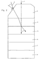
- a four-beam configuration in a so-called umbrella-like arrangement in a so-called umbrella-like arrangement (umbrella-like configuration) (see AI Petsas et al., Phys. Rev. A 1994, 50, page 5173 ), as shown in Fig. 1 , three of the rays - hereinafter called secondary rays - or their wave vectors evenly distributed on a conical surface, all three wave vectors point towards the top of the cone.
- Another beam - referred to below as reference beam - lies on the axis of the cone and also points to the top of the cone.
- the reference beam forms the incidence solder to the photoresist layer.
- photoresists were used, e.g. the photoresist SU-8. These were applied to glass substrates (diameter 25 mm, thickness 5-7 mm) with a spin coater (spin coating). This achieved layer thicknesses of about 10 to 50 microns. To substantially remove the solvent, the sample was then heated to 65 ° C for about 1 hour (soft bake).
- the subsequent exposure in the multi-beam interference structure was in the umbrella-like arrangement (umbrella-like configuration).
- the four mutually coherent beams were obtained by splitting the beam of a laser by means of beam splitters. Suitable for this purpose is, for example, a Q-switched, frequency-tripled (355 nm wavelength), by seeding longitudinally one-mode Nd: YAG pulse laser. Due to the pulse duration of approx. 6 ns, blur was avoided. It is advantageous if the intensity and let the polarization of each sub-beam be set separately. This means in particular that the beams can be set up independently of each other elliptically, circularly or linearly polarized.
- a special embodiment consists in that the reference beam is circular and the three secondary beams are linear, namely polarized in their respective plane of incidence (so-called p-polarization).
- the ratio of the beam energies was 1.5: 1: 1: 1 for reference beam: Sub beam No. 1: Sub beam No. 2: Sub beam No. 3.
- the photoresist was exposed with a single laser pulse.
- the pulse energy necessary for this exposure was about 8 mJ before the division into four partial beams.
- the energy averaged over the cross section of the laser beam per area was about 16 mJ / cm 2 . This resulted in a filling factor of the structures of about 50%.
- This angle is achieved according to the invention by connecting a specially designed multilayer: For this purpose, a modified retroreflector in which the tip was cut off and the cut surface was polished was used (truncated pyramid). The beam guidance is shown in FIG. 2 .
- the light beams 1 , 2 are guided by the optical element 3 , which is designed as Einkoppel prism, via an immersion substance 4 of distilled water in the photoresist volume 5 , which is applied in this embodiment on a glass substrate 6 .
- a black anodized aluminum sheet as absorber 8 completes the beam path.
- substrate 6 and absorber 8 is another immersion substance 7 made of oil. Without these decoupling measures would be at the Underside of the substrate of the reference beam 1 partially and the other three beams 2 totally reflected and interfere with interference interference.
- the photoresist exposed to the interference pattern was heated to polymerization for about 6 minutes, with the temperature rising from about 65 ° C to about 92 ° C (post-exposure bake). After removal from the oven and cooling, the sample was allowed to rest for at least 30 minutes.
- the samples show cracks that occur due to the uneven volume change (swelling or shrinkage) during the development process. Sometimes the sample dissolves completely or partially from the substrate; Template are then also substrate-free. The area of the resulting fragments is about 1 mm 2 .
- the shape and size of the fragments can be controlled by targeted insertion of cracks in the photoresist (as predetermined breaking points).
- a targeted non-destructive detachment of the template from the substrate can be achieved by placing in a bath with heated or boiling hydrochloric acid.
- a further advantageous embodiment of the invention is the exposure of the photoresist through the glass substrate.
- the substrate 6, including the photoresist volume 5 applied thereto by means of spin coating is turned over. The irradiation occurs from the very flat side of the photoresist, which rests perfectly on the substrate 6 , rather than from the free, generally less perfect, facing away surface of the photoresist layer.
- All partial beams experience more or less strong reflection losses when entering from the outer medium (eg air) into the prism, which are avoided by providing all the entrance surfaces with antireflection layers suitable for the angle of incidence and the respective polarization.
- the outer medium eg air
- the inclined entrance surfaces are oriented such that the rays produce the desired one, especially at normal entry into the side surfaces of the prism Give angles in the photoresist.
- the residual reflection also present in the case of antireflection coating
- the reflection of a beam in itself is particularly easy to verify.
- an antireflection coating results irrespective of the beam polarization.
- the immersion substance and the material of which the prism is made are selected so that they have the same refractive index as the photoresist. This also low back reflections are avoided and increases the coupling efficiency.
- the lateral entry surfaces are just oriented so that they with correct adjustment with respect to the incoming rays are below the Brewster angle.
- the correct setting of the angle can be detected very precisely as the disappearance of the reflection of the p-portion of the beam.
- all four beams are set up parallel to each other, but they are laterally offset from each other.
- the entrance faces of the prism are oriented to give the required angles by refraction upon entry into the prism.
- the required parallelism of the beams can be realized with high accuracy, for example by means of beam splitters made of plane-parallel plates of suitable thickness. The task of precise angle adjustment between the four beams is thus almost completely transferred to the very well-controlled production of calculated angles in prism production.
- another prism which may be identical to the prism used for the coupling, is used for coupling out those light beams which have already passed through the photoresist and the substrate.
- the decoupled beams are then available for further analysis, for example for the control of the polarization states of the beams.
- a further advantageous embodiment of the beam configuration consists in dividing the laser beam into four partial beams, the wave vectors of two beams lying in one plane and the wave vectors of the two other beams in a further plane perpendicular to the first plane.
- the wave pair whose wave vectors lie in the first plane propagates counter to the wave pair in the other plane ( KI Petsas et al., PRA 1994, 50, page 5173 ).
- the bisector between two partial beams is common to both pairs and at the same time forms the solder to the photoresist layer.
- the photoresist layer is exposed from two sides, ie, two half-spaces separated by the photoresist layer.
- areas of the photoresist are specifically masked during the exposure, so that only parts of the interference pattern are preserved in the photoresist. This gives, for example, template selectable edge shape. This procedure is of interest for both positive and negative photoresists, because the unexposed parts, ie the parts covered by the mask, either stop or become dissolved.
- the photoresist can be overexposed in certain areas in certain embodiments. Thereafter, the multi-beam interference technique described above is also applied to the still unexposed portions. With a negative photoresist, the overexposed areas form solid material. The result is a photo-resist template, which is surrounded by solid material. This allows for better handling of the resulting photoresist template, especially when the entire photoresist layer is peeled from the substrate. By changing to positive photoresist complementary structures can be realized.
- a further photoresist layer for example, also from SU-8, which then with an interference pattern is exposed.
- a template is obtained which, after detachment from the substrate, lies on a solid material layer of photoresist (adhesive layer).
- This adhesive layer then forms a substrate of small thickness, which has the same chemical composition as the photoresist structure.
- the absorption of the light during propagation through the photoresist there is a decrease in the light intensity along the direction of propagation and thus, in a further embodiment, the possibility of a variation of the filling factor with the depth (gradient structure).
- the absorption and thus the strength of the variation can be influenced with the depth.
- the effective beam cross section is different than that of the original, for example, round beam.
- a better overlap of all beams is achieved by preforming them with known optical elements such as anamorphic prism pairs in their cross-section so that they effectively become circular by the oblique incidence.
- a special embodiment of the method according to the invention consists in using only three beams. As a result, two-dimensional periodic photoresist structures can be produced. With the aid of a coupling prism according to the invention, larger angles between the beams in the photoresist volume can be realized and thus smaller lattice constants than with direct irradiation from air.
Landscapes
- Physics & Mathematics (AREA)
- Engineering & Computer Science (AREA)
- Nanotechnology (AREA)
- General Physics & Mathematics (AREA)
- Optics & Photonics (AREA)
- Chemical & Material Sciences (AREA)
- Microelectronics & Electronic Packaging (AREA)
- Crystallography & Structural Chemistry (AREA)
- Life Sciences & Earth Sciences (AREA)
- Biophysics (AREA)
- Exposure And Positioning Against Photoresist Photosensitive Materials (AREA)
- Exposure Of Semiconductors, Excluding Electron Or Ion Beam Exposure (AREA)
- Light Receiving Elements (AREA)
- Steroid Compounds (AREA)
- Optical Communication System (AREA)
- Diffracting Gratings Or Hologram Optical Elements (AREA)
- Holo Graphy (AREA)
- Application Of Or Painting With Fluid Materials (AREA)
Description
- Die Erfindung betrifft Verfahren zur Herstellung von Strukturen in einem Volumen aus Photolack (Photolackvolumen).
- Die
US 3,635,540 A und dieGB 1 289 095 A - Um Photolackstrukturen herzustellen, wird entsprechend der in der
WO 01/22133 A1 - Der Erfindung liegt die Aufgabe zugrunde, eine größere Vielfalt an Photolackstrukturen herzustellen.
- Gelöst wird diese Aufgabe durch die Merkmale des Patentanspruchs 1 und des Patentanspruchs 3. Die Unteransprüche beschreiben vorteilhafte Ausgestaltungen der Erfindung.
- Bei der Einstrahlung von Lichtstrahlen in ein Photolackvolumen aus einem äußeren Medium (z. B. Luft) mit geringerer Brechzahl als Photolack ist der Bereich realisierbarer Ausbreitungsrichtungen der Lichtstrahlen im Inneren des Photolackvolumens in unerwünschter Weise eingeschränkt. Der Grund hierfür besteht darin, dass beim Übergang vom äußeren, optisch dünneren Medium in den Photolack die Brechung der Strahlen zu berücksichtigen ist, die sich durch Wahl der Einstrahlrichtung, wie in der
WO 01/22133 A1 - Der maximal erreichbare Brechungswinkel eines Strahles bei Einstrahlung aus dem äußeren Medium ist der Grenzwinkel der Totalreflexion, der bei Luft und typischen Photolacken einen Wert von ca. 36° annimmt. Dieser Wert würde streifenden Einfall erfordern. Winkel im Inneren des Photolacks, die größer als der Grenzwinkel der Totalreflexion sind, lassen sich durch Wahl der Einstrahlrichtung daher nicht einstellen.
- Zunächst wird ein Photolackvolumen mit zwei, drei, vier, fünf, sechs oder mehr Lichtstrahlen belichtet, die sich innerhalb des Photolackvolumens so überlagern, dass darin ein Interferenzmuster erzeugt wird, wobei im Falle von zwei Lichtstrahlen mindestens zwei Belichtungen des Photolackvolumens vorgesehen sind, zwischen denen die Lichtstrahlen (und das Photolackvolumen relativ zueinander bewegt werden. Im Falle von drei oder mehr Lichtstrahlen können ebenfalls zwei oder mehr Belichtungen des Photolackvolumens durchgeführt werden, zwischen denen die Lichtstrahlen (und das Photolackvolumen relativ zueinander bewegt werden. Anschließend wird dieses Photolackvolumen einem Entwicklungsprozess unterworfen, wodurch eine dem Interferenzmuster entsprechende Photolackstruktur erzeugt wird.
- Erfindungsgemäß werden die zwei, drei, vier, fünf, sechs oder mehr teilkohärenten Lichtstrahlen über einen Vielflächner in das Photolackvolumen hinein oder aus dem Photolackvolumen heraus geführt. Dadurch wird es möglich, Strahlwinkel im Inneren des Photolackes jenseits des Grenzwinkels der Totalreflexion zugänglich zu machen, d. h. Winkel zwischen den Strahlen im Inneren des Photolackes, die bei direkter Einstrahlung aus dem äußeren Medium nicht zugänglich sind. Bei Luft als äußeres Medium ist dieses der beträchtliche Wertebereich zwischen ca. 36° und 90°.
- Darüber hinaus werden auch bei Brechungswinkeln unterhalb, insbesondere auch in der Nähe des Grenzwinkels der Totalreflexion, durch die Verwendung eines Vielflächners die Einkopplung und die Auskopplung der Lichtstrahlen wesentlich verbessert.
- Erfindungsgemäß werden die optischen Elemente als Vielflächner, vorzugsweise als Teilprisma, bevorzugt als Pyramide, besonders bevorzugt als Pyramidenstumpf, oder in einer weiteren Ausgestaltung als Kugelabschnitt ausgestaltet.
- Um den Übergang der Strahlen vom optischen Element in das Photolackvolumen zu ermöglichen, kann der Photolack direkt auf das optische Element aufgebracht werden. In einer anderen Ausgestaltung wird eine Immersionssubstanz zwischen das optische Element und das Photolackvolumen eingebracht. Wird der Photolack in flüssigem Zustand belichtet, kann die Immersionssubstanz gegebenenfalls entfallen.
- Ein besonderer Vorteil des erfindungsgemäßen Verfahrens besteht darin, dass nicht nur einige ausgewählte, sondern alle Bravais-Gitter hergestellt werden können. Dies gilt insbesondere für die im Hinblick auf eine dreidimensionale vollständige Bandlücke interessante kubisch flächenzentrierte (fcc) Struktur (siehe K. Busch, S. John, PRE 1998, 58, S. 3896).
- Der Brechzahlunterschied zwischen Luft und Photolack (1 bzw. 1,6 bei Photolack SU-8) reicht vermutlich jedoch nicht aus, um eine vollständige dreidimensionale Bandlücke im Photonischen Kristall zu erzielen. Durch Auffüllen (Infiltration) der Poren der Photolackstruktur (Templat, verlorene Form) mit einem transparenten und stark - brechenden Material und nachfolgendem Entfernen des Photolackes kann die komplementäre Struktur aus hochbrechendem Material hergestellt werden. Hierzu ist erforderlich, dass sowohl die Poren als auch das Photolack-Gerippe jeweils zusammenhängend sind. Die Poren müssen miteinander verbunden sein, damit zum einen der unpolymerisierte Photolack herausgelöst werden kann und zum anderen die Poren anschließend durchgängig mit hochbrechendem Material befüllt (infiltriert) werden können. Die Photolackstruktur muss zusammenhängend sein, damit sie mechanisch stabil ist und nicht auseinander fällt.
- Es wird darauf hingewiesen, dass in der
WO 01/22133 A1 - Erfindungsgemäße Photolackstrukturen eignen sich darüber hinaus als Effektbeschichtung von Oberflächen, als Partikelfilter, als Mikromischer, als Volumengitter, als Beugungsstruktur oder dispersive Struktur, als Photonischer Kristall oder als verlorene Form für einen Photonischen Kristall.
- Im Folgenden wird die Erfindung mit Hilfe der Figuren beschrieben. Es zeigt
- Fig. 1
- die Realisierung von Strahlwinkeln in einem Photolack über den Grenzwinkel der Totalreflexion hinaus und
- Fig. 2
- einen schematischen Schichtaufbau für das Verfahren.
- Durch die Brechung an der Luft-Photolack-Grenzfläche wird ein Lichtstrahl mit dem Einfallswinkel α 10 zur Oberflächennormale (Lot) des Photolackes 9 in den Photolack 9 gemäß dem Snelliusschen Brechungsgesetz

gebrochen, wobei γ 11 den Winkel des gebrochenen Lichtstrahles bezüglich der Oberflächennormalen im Innern des Photolacks bezeichnet. Für den verwendeten Photolack betrug bei der Belichtung n ≈ 1,67. - Bei einer Vierstrahl-Konfiguration in so genannter regenschirmartiger Anordnung (umbrella-like configuration)(siehe K. I. Petsas et al., Phys. Rev. A 1994, 50, Seite 5173) liegen, wie in Fig. 1 dargestellt, drei der Strahlen - im Folgenden Nebenstrahlen genannt - bzw. deren Wellenvektoren gleichmäßig verteilt auf einem Kegelmantel, wobei alle drei Wellenvektoren zur Spitze des Kegels hin zeigen. Ein weiterer Strahl - im Folgenden Referenzstrahl genannt - liegt auf der Achse des Kegels und weist ebenso zur Spitze des Kegels hin. Der Referenzstrahl bildet das Einfallslot zur Photolackschicht. Um mit dieser Strahlenkonfiguration z. B. eine Struktur mit fcc-Translationssymmetrie herzustellen, muss der Winkel zwischen den Nebenstrahlen und dem Referenzstrahl im Inneren des Photolackes γfcc = arccos (7/9) ≈ 38, 94° betragen.
- Dessen Realisierung steht zunächst die Totalreflexion entgegen, denn der Grenzwinkel der Totalreflexion γGrenz 11 für den Photolack SU-8 beträgt γGrenz = arcsin (1/nPhotolack) ≈ 36,78° < γfcc. Diese Tatsache hindert daran, den inneren Winkel γfcc 12 und überhaupt alle Winkel γ > γGrenz zwischen dem Referenzstrahl und den Nebenstrahlen im Inneren des Photolackes bei direkter Einstrahlung aus Luft zu realisieren. Daher sind Strukturen mit fcc-Translationssymmetrie und beispielsweise auch mit einfach kubischer (sc) Translationssymmetrie (γsc = arccos((√3)/6) ≈ 73, 22°) in dieser Konfiguration durch Belichtung direkt aus Luft nicht herstellbar.
- Für das Ausführungsbeispiel wurden kommerziell erhältliche Negativ-Photolacke verwendet, z.B. der Photolack SU-8. Diese wurden auf Glassubstrate (Durchmesser 25 mm, Dicke 5-7 mm) mit einer Lackschleuder aufgebracht (Spincoating). Damit erreichte man Schichtdicken von ca. 10 bis 50 µm. Um das Lösungsmittel weitgehend zu entfernen, wurde die Probe anschließend für ca. 1 Stunde auf 65° C erwärmt (soft bake).
- Die nachfolgende Belichtung im Mehrstrahl-Interferenz-Aufbau erfolgte in der regenschirmartigen Anordnung (umbrella-like configuration). Die vier zueinander kohärenten Strahlen wurden durch Aufteilung des Strahles eines Lasers mittels Strahlteilern erhalten. Geeignet hierfür ist beispielsweise ein gütegeschalteter, frequenzverdreifachter (355 nm Wellenlänge), durch seeding longitudinal einmodiger Nd :YAG-Pulslaser. Durch die Impulsdauer von ca. 6 ns wurde Verwackelungsinschärfe vermieden. Vorteilhaft ist es, wenn sich die Intensität und die Polarisation jedes Teilstrahles getrennt voneinander einstellen lassen. Dies bedeutet insbesondere, dass die Strahlen unabhängig voneinander elliptisch, zirkular oder linear polarisiert eingerichtet werden können. Eine besondere Ausgestaltung besteht darin, dass der Referenzstrahl zirkular und die drei Nebenstrahlen linear, und zwar in ihrer jeweiligen Einfallsebene (sog. p-Polarisation) polarisiert sind. Das Verhältnis der Strahlenergien betrug 1,5:1:1:1 für Referenzstrahl : Nebenstrahl Nr. 1 : Nebenstrahl Nr. 2 : Nebenstrahl Nr. 3.
- Mit diesen Strahlen wurde der Photolack mit einem einzelnen Laser-Impuls belichtet. Die für diese Belichtung notwendige Impulsenergie betrug vor der Aufteilung in vier Teilstrahlen ca. 8 mJ. Bei einer Strahl-Querschnittsfläche von ca. 1/2 cm2 betrug die über den Querschnitt des Laserstrahls gemittelte Energie pro Fläche ca. 16 mJ/cm2. Dies führte zu einem Füllfaktor der Strukturen von ca. 50%.
- Um eine Struktur mit fcc-Translationssymmetrie im Photolack zu generieren, muss der halbe Öffnungswinkel γ des Kegels im Innern des Photolackes die Bedingung γ = arccos (7/9) ≈ 38,94° erfüllen. Dieser Winkel wird erfindungemäß durch Vorschalten eines speziell ausgeführten Vielflächners erreicht: Hierfür wurde ein modifizierter Retroreflektor, bei dem die Spitze abgetrennt und die Schnittfläche poliert wurde, verwendet (Pyramidenstumpf). Die Strahlführung ist in Fig. 2 dargestellt.
- Die Lichtstrahlen 1, 2 werden vom optischen Element 3, das als Einkoppel-Prisma ausgestaltet ist, über eine Immersionssubstanz 4 aus destilliertem Wasser in das Photolackvolumen 5 geleitet, das in diesem Ausführungsbeispiel auf einem Glassubstrat 6 aufgebracht ist. Um Rückreflexe von der Unterseite des Substrates 6 zu unterdrücken, schließt ein schwarz eloxiertes Aluminiumblech als Absorber 8 den Strahlengang ab.
Zwischen Substrat 6 und Absorber 8 befindet sich eine weitere Immersionssubstanz 7 aus Öl. Ohne diese Auskoppel-Maßnahmen würden an der Unterseite des Substrats der Referenzstrahl 1 teilweise und die anderen drei Strahlen 2 total reflektiert und sich der Interferenz störend überlagern. - Der mit dem Interferenzmuster belichtete Photolack wurde zur Polymerisation für ca. 6 Minuten erwärmt, wobei die Temperatur von ca. 65° C auf ca. 92° C anstieg (post exposure bake). Nach dem Herausnehmen aus dem Ofen und Abkühlung ließ man die Probe für mindestens 30 Minuten ruhen.
- Die Proben wurden zur Entwicklung für ca. 30 Minuten bis ca. 1 Stunde in einem Bad mit SU-8-Entwickler, der 1-Methoxy-2-propylacetat enthielt, ruhend stehen gelassen. Durch den Entwicklungsprozess wurden die schwach belichteten Bereiche des Photolacks im Entwickler aufgelöst; die stärker belichteten hingegen blieben stehen (SU-8 ist ein sog. "negativer" Photolack). Ein ca. zehnminütiges Bad in 2-Propanol schloss den Entwicklungsprozess ab.
- Die Proben zeigen Risse, die wegen der ungleichmäßigen Volumenänderung (Quellung bzw. Schrumpfung) während des Entwicklungsprozesses auftreten. Manchmal löst sich die Probe ganz oder teilweise vom Substrat; Template stehen dann auch substratfrei zur Verfügung. Die Fläche der resultierenden Bruchstücke beträgt ca. 1 mm2. Form und Größe der Bruchstücke kann durch gezieltes Einbringen von Ritzen in den Photolack (als Soll-Bruchstellen) kontrolliert werden.
- Durch Verwendung eines positiven an Stelle eines negativen Photolackes erhält man die jeweils invertierte Struktur, die sich bei Verwendung eines negativen Lackes ergeben würde.
- Ein gezieltes zerstörungsfreies Ablösen des Templats vom Substrat erreicht man durch Einbringen in ein Bad mit erwärmter oder kochender Salzsäure.
- Eine weitere vorteilhafte Ausgestaltung der Erfindung ist die Belichtung des Photolacks durch das Glassubstrat hindurch. Hierzu wird das Substrat 6 einschließlich des hierauf mittels Spincoating aufgebrachten Photolackvolumens 5 umgedreht. Die Einstrahlung erfolgt von der sehr ebenen Seite des Photolacks, der auf dem Substrat 6 perfekt aufliegt, anstatt von der freien, im Allgemeinen weniger perfekten abgewandten Oberfläche der Photolackschicht.
- Alle Teilstrahlen erfahren beim Eintritt aus dem äußeren Medium (z. B. Luft) in das Prisma mehr oder weniger starke Reflexionsverluste, die dadurch vermieden werden, dass alle Eintrittsflächen mit für den Einfallswinkel und die jeweilige Polarisation geeigneten Antireflexschichten versehen werden.
- Für einen gegebenen inneren Winkel im Photolack und den hiervon (wegen der im Allgemeinen anderen Brechzahl) abweichenden Winkel im Prisma werden in einer besonders vorteilhaften Ausgestaltung die schräg stehenden Eintrittsflächen so orientiert hergestellt, dass die Strahlen gerade bei senkrechtem Eintritt in die Seitenflächen des Prismas den gewünschten Winkel im Photolack ergeben. Auf diese Weise lässt sich die korrekte Einstrahlrichtung besonders leicht und genau kontrollieren, weil der (auch bei Antireflex-Beschichtung vorhandene) restliche Rückreflex als Indikator genutzt werden kann: Die Reflexion eines Strahles in sich (Retroreflexion) ist besonders einfach verifizierbar. Außerdem ergibt sich eine Antireflex-Beschichtung unabhängig von der Strahlpolarisation.
- In einer weiteren vorteilhaften Ausgestaltung werden die Immersionssubstanz und das Material, aus dem das Prisma besteht, so gewählt, dass sie die gleiche Brechzahl wie der Photolack haben. Dadurch werden auch geringe Rückreflexe vermieden und die Einkoppeleffizienz erhöht.
- In einer weiteren Ausgestaltung werden die seitlichen Eintrittsflächen gerade so orientiert, dass sie bei korrekter Justierung bezüglich der eintretenden Strahlen unter dem Brewster-Winkel stehen. Hierdurch lässt sich die korrekte Einstellung des Winkels sehr präzise als Verschwinden der Reflexion des p-Anteils des Strahles erkennen.
- In einer weiteren Ausgestaltung werden alle vier Strahlen parallel zueinander eingerichtet, wobei sie jedoch gegeneinander seitlich versetzt sind. Die Eintrittsflächen des Prismas werden so orientiert, dass sich die erforderlichen Winkel durch Brechung beim Eintritt in das Prisma ergeben. Die erforderliche Parallelität der Strahlen lässt sich mit hoher Genauigkeit beispielsweise durch Strahlteiler aus planparallelen Platten geeigneter Dicke verwirklichen. Die Aufgabe zur präzisen Winkeleinstellung zwischen den vier Strahlen wird auf diese Weise fast vollständig auf die sehr gut beherrschte Herstellung berechneter Winkel bei der Prismenfertigung übertragen.
- Anstelle eines Absorbers 8 wird in einer weiteren vorteilhaften Ausgestaltung ein weiteres Prisma, das identisch mit dem für die Einkopplung verwendeten Prisma sein kann, zum Auskoppeln derjenigen Lichtstrahlen, die den Photolack und das Substrat bereits durchlaufen haben, verwendet. Die ausgekoppelten Strahlen stehen dann für weitere Analysen zur Verfügung, etwa für die Kontrolle der Polarisationszustände der Strahlen.
- Eine weitere vorteilhafte Ausgestaltung der Strahlkonfiguration besteht darin, den Laserstrahl in vier Teilstrahlen aufzuteilen, wobei die Wellenvektoren von zwei Strahlen in einer Ebene liegen und die Wellenvektoren der beiden anderen Strahlen in einer weiteren Ebene, die senkrecht zur ersten Ebene steht. Das Wellenpaar, deren Wellenvektoren in der ersten Ebene liegen, propagiert dabei gegenläufig zu dem Wellenpaar in der anderen Ebene (K. I. Petsas et al., PRA 1994, 50, Seite 5173). Die Winkelhalbierende zwischen zwei Teilstrahlen ist beiden Paaren gemeinsam und bildet gleichzeitig das Lot zur Photolackschicht.
- Das folgende Beispiel von vier Richtungsvektoren für die Wellenpropagation ergibt in der obigen Konfiguration eine fcc-Struktur:
[2,0,1], [-2,0,1], [0,2,-1], [0,-2,-1]. - Die Photolackschicht wird von zwei Seiten, d.h. aus zwei Halbräumen, die durch die Photolackschicht voneinander getrennt sind, belichtet. Der innere Winkel der Strahlen zum Lot der Photolackschicht beträgt dann jeweils γfcc = 0,5 * arccos(-3/5) ≈ 63,43°. Dieser Winkel im Inneren des Photolackes ist bei direkter Einstrahlung aus Luft nicht zu erreichen.
- Daraus ergibt sich, dass die Strahlen von einem Halbraum in den Photolack eingekoppelt werden müssen und die Strahlen aus dem anderen Halbraum kommend ausgekoppelt werden müssen. Dies wird dadurch erreicht, dass die Photolackschicht zwischen zwei Dachprismen liegt, wobei die Dachflächen nach außen zeigen und die Prismen um 90° gegen einander verdreht sind. Jedes dieser Dachprismen dient für das eine Strahlenpaar als Einkopplungselement und für das andere als Auskopplungselement. Dies geschieht durch Abschrägen (Modifizieren) der senkrechten Seitenflächen der Prismen zu Pyramiden. Durch jedes dieser modifizierten Dachprismen tritt das eine Strahlenpaar ein und das andere Strahlenpaar aus. Um das Licht ein- und wieder auszukoppeln braucht man zwischen dem modifizierten Dachprisma und der Photolack-Schicht bzw. dem Substrat je eine Schicht aus einer geeigneten Immersionssubstanz 4, 7.
- In einer weiteren Ausgestaltung werden während der Belichtung Bereiche des Photolacks gezielt abgedeckt (Maskierung), so dass nur Teile des Interferenzmusters im Photolack konserviert werden. Dadurch erhält man beispielsweise Template wählbarer Randform. Dieses Vorgehen ist sowohl bei positiven als auch bei negativen Photolacken von Interesse, weil die unbelichteten - d. h. die durch die Maskierung abgedeckten - Teile entweder stehen bleiben bzw. aufgelöst werden.
- Durch eine strukturierte Vor- oder Nachbelichtung des Photolacks etwa mittels konventioneller Maskentechnik kann der Photolack in einer weiteren vorteilhaften Ausgestaltung in bestimmten Bereichen überbelichtet werden. Danach wird die oben beschriebene Vielstrahl-Interferenztechnik auch auf die noch unbelichteten Partien angewendet. Bei einem negativen Photolack bilden die überbelichteten Bereiche Vollmaterial.
So entsteht ein Photolacktemplat, das von Vollmaterial umgeben ist. Dies ermöglicht eine bessere Handhabung des resultierenden Photolacktemplates, insbesondere dann, wenn die gesamte Photolackschicht vom Substrat abgelöst wird. Durch Wechsel zu positivem Photolack sind jeweils komplementäre Strukturen realisierbar. - Auf eine Schicht negativen Photolacks z. B. aus SU-8, die durch eine UV-Lampe vollständig überbelichtet und danach wahlweise entwickelt wurde (passivierte Haftschicht), kann man in einer weiteren Ausgestaltung eine weitere Photolack-Schicht zum Beispiel ebenfalls aus SU-8 aufbringen, die dann mit einem Interferenzmuster belichtet wird. Nach der Entwicklung dieser Schicht, die auf der Haftschicht liegt, erhält man ein Templat, das nach Ablösung vom Substrat auf einer Vollmaterial-Schicht aus Photolack (Haftschicht) liegt. Diese Haftschicht bildet dann ein Substrat von geringer Dicke, das die gleiche chemische Zusammensetzung aufweist wie die Photolack-Struktur.
- Wegen der Absorption des Lichtes bei Propagation durch den Photolack ergibt sich eine Abnahme der Lichtintensität längs der Propagationsrichtung und damit in einer weiteren Ausgestaltung die Möglichkeit einer Variation des Füllfaktors mit der Tiefe (Verlaufs-Struktur). Durch geeignete Zusätze zum Photolack und/oder durch das Auftragen mehrerer Schichten verschiedener Lacke, deren Lichtempfindlichkeiten sich voneinander unterscheiden, kann die Absorption und damit die tärke der Variation mit der Tiefe beeinflußt werden.
- mgekehrt führt eine Vermeidung der Absorption etwa durch Reinigung it Entfernung absorbierender Beimischungen zu einer homogeneren Struktur der Photolackstruktur.
- Die Strahlen fallen schräg in den Photolack ein. Dadurch ist der effektive Strahlquerschnitt anders als derjenige des ursprünglichen zum Beispiel runden Strahls. Eine bessere Überlappung aller Strahlen erreicht man dadurch, dass man diese mit bekannten optischen Elementen wie etwa mit anamorphischen Prismenpaaren in ihrem Querschnitt derart vor-verformt, dass sie durch den schrägen Einfall effektiv kreisförmig werden.
- Bei Ausbreitung des Referenzstrahles in die entgegen gesetzte Richtung im Vergleich zur umbrella-like-Konfiguration erhält man andere Strukturen, insbesondere Spiralstrukturen.
- Eine spezielle Ausgestaltung des erfindungsgemäßen Verfahrens besteht darin, nur drei Strahlen zu verwenden. Dadurch lassen sich zweidimensional periodische Photolack-Strukturen erzeugen. Mit Hilfe eines erfindungsgemäßen Einkoppelprismas lassen sich größere Winkel zwischen den Strahlen im Photolackvolumen realisieren und damit kleinere Gitterkonstanten als bei direkter Einstrahlung aus Luft.
Claims (15)
- Verfahren zur Herstellung von Photolackstrukturen, bei dem ein Photolackvolumen (5) mit mindestens drei Lichtstrahlen, die einander innerhalb des Photolackvolumens (5) überlagern, mindestens einmal belichtet wird und danach einem Entwicklungsprozess unterworfen wird, wobei die Lichtstrahlen durch mindestens ein transparentes optisches Element (3) laufen, wobei das optische Element (3) ein Vielflächner mit ebenen oder gekrümmten Flächen ist.
- Verfahren zur Herstellung von Photolackstrukturen nach Anspruch 1, dadurch gekennzeichnet, dass mindestens zwei Belichtungen des Photolackvolumens (5) vorgesehen sind, zwischen denen die Lichtstrahlen und das Photolackvolumen (5) relativ zueinander bewegt werden.
- Verfahren zur Herstellung von Photolackstrukturen, bei dem ein Photolackvolumen (5) mit mindestens zwei Lichtstrahlen (1, 2), die einander innerhalb des Photolackvolumens (5) überlagern, mindestens zweimal belichtet wird, wobei zwischen den mindestens zwei Belichtungen des Photolackvolumens (5) die Lichtstrahlen (1, 2) und das Photolackvolumen (5) relativ zueinander bewegt werden, und danach einem Entwicklungsprozess unterworfen wird, wobei die Lichtstrahlen (1, 2) durch mindestens ein transparentes optisches Element (3) laufen, wobei das optische Element (3) ein Vielflächner mit ebenen oder gekrümmten Flächen ist.
- Verfahren zur Herstellung von Photolackstrukturen nach einem der Ansprüche 1 bis 3, dadurch gekennzeichnet, dass als Vielflächner ein Teilprisma mit ebenen Flächen verwendet wird.
- Verfahren zur Herstellung von Photolackstrukturen nach Anspruch 4, dadurch gekennzeichnet, dass als Teilprisma eine Pyramide verwendet wird.
- Verfahren zur Herstellung von Photolackstrukturen nach Anspruch 4, dadurch gekennzeichnet, dass als Teilprisma ein Pyramidenstumpf verwendet wird.
- Verfahren zur Herstellung von Photolackstrukturen nach einem der Ansprüche 1 bis 3, dadurch gekennzeichnet, dass als Vielflächner ein Kugelabschnitt verwendet wird.
- Verfahren zur Herstellung von Photolackstrukturen nach einem der Ansprüche 1 bis 7, dadurch gekennzeichnet, dass das Photolackvolumen (5) direkt auf einem der optischen Elemente (3) aufgebracht ist.
- Verfahren zur Herstellung von Photolackstrukturen nach einem der Ansprüche 1 bis 8, dadurch gekennzeichnet, dass zwei optische Elemente eingesetzt werden, zwischen denen sich das Photolackvolumen (5) befindet.
- Verfahren zur Herstellung von Photolackstrukturen nach einem der Ansprüche 1 bis 9, dadurch gekennzeichnet, dass sich zwischen mindestens einem der optischen Elemente (3) und dem Photolackvolumen (5) eine Immersionssubstanz (4) befindet.
- Verfahren zur Herstellung von Photolackstrukturen nach einem der Ansprüche 1 bis 10, dadurch gekennzeichnet, dass die Lichtstrahlen (1, 2) hinsichtlich ihrer Intensität, Phase und Polarisation unabhängig voneinander eingerichtet sind.
- Verfahren zur Herstellung von Photolackstrukturen nach einem der Ansprüche 1 bis 11, dadurch gekennzeichnet, dass einzelne Bereiche auf der Oberfläche des Photolackvolumens (5) mit mindestens einer Schattenmaske abgedeckt sind.
- Verfahren zur Herstellung von Photolackstrukturen nach einem der Ansprüche 1 bis 12, dadurch gekennzeichnet, dass das Photolackvolumen (5) zusätzlich mit einem einzelnen Strahl belichtet wird.
- Verfahren zur Herstellung von Photolackstrukturen nach einem der Ansprüche 1 bis 13, dadurch gekennzeichnet, dass das Photolackvolumen (5) in Segmente zerlegt ist.
- Verfahren zur Herstellung von Photolackstrukturen nach einem der Ansprüche 1 bis 14, dadurch gekennzeichnet, dass das Photolackvolumen auf ein weiteres mit mindestens einem Strahl belichtetes Photolackvolumen aufgebracht ist.
Applications Claiming Priority (3)
| Application Number | Priority Date | Filing Date | Title |
|---|---|---|---|
| DE10233309 | 2002-07-22 | ||
| DE10233309 | 2002-07-22 | ||
| PCT/EP2003/007819 WO2004010222A2 (de) | 2002-07-22 | 2003-07-18 | Verfahren zur herstellung von photolackstrukturen |
Publications (2)
| Publication Number | Publication Date |
|---|---|
| EP1523697A2 EP1523697A2 (de) | 2005-04-20 |
| EP1523697B1 true EP1523697B1 (de) | 2007-12-05 |
Family
ID=30469035
Family Applications (1)
| Application Number | Title | Priority Date | Filing Date |
|---|---|---|---|
| EP03765041A Expired - Lifetime EP1523697B1 (de) | 2002-07-22 | 2003-07-18 | Verfahren zur herstellung von photolackstrukturen |
Country Status (6)
| Country | Link |
|---|---|
| US (1) | US7407737B2 (de) |
| EP (1) | EP1523697B1 (de) |
| JP (1) | JP2005534050A (de) |
| AT (1) | ATE380359T1 (de) |
| DE (2) | DE50308738D1 (de) |
| WO (1) | WO2004010222A2 (de) |
Families Citing this family (6)
| Publication number | Priority date | Publication date | Assignee | Title |
|---|---|---|---|---|
| US7492442B2 (en) * | 2004-08-27 | 2009-02-17 | Asml Holding N.V. | Adjustable resolution interferometric lithography system |
| DE102005025207B4 (de) * | 2005-05-25 | 2015-07-23 | E.G.O. Elektro-Gerätebau GmbH | Wärmedämmung für eine Strahlungsheizeinrichtung, Strahlungsheizeinrichtung und Elektro-Haushaltsgerät |
| US7708924B2 (en) * | 2005-07-21 | 2010-05-04 | Asml Netherlands B.V. | Imprint lithography |
| US7692771B2 (en) * | 2005-05-27 | 2010-04-06 | Asml Netherlands B.V. | Imprint lithography |
| WO2014201414A1 (en) * | 2013-06-14 | 2014-12-18 | The Trustees Of Dartmouth College | Methods for fabricating magnetic devices and associated systems and devices |
| US10345705B2 (en) | 2013-07-12 | 2019-07-09 | Xerox Corporation | Photolithographic patterning of a cylinder |
Family Cites Families (12)
| Publication number | Priority date | Publication date | Assignee | Title |
|---|---|---|---|---|
| GB1267858A (en) * | 1968-09-19 | 1972-03-22 | Agfa Gevaert Ag | Holographic process |
| GB1289095A (de) * | 1968-10-02 | 1972-09-13 | ||
| DE2224350C3 (de) * | 1972-05-18 | 1975-01-09 | Siemens Ag, 1000 Berlin Und 8000 Muenchen | Anordnung zum Auslesen von holografisch gespeicherten Informationen |
| JPS61190368A (ja) * | 1985-02-20 | 1986-08-25 | Matsushita Electric Ind Co Ltd | 微細パタ−ンの形成方法 |
| US5017263A (en) * | 1988-12-23 | 1991-05-21 | At&T Bell Laboratories | Optoelectronic device package method |
| GB8922341D0 (en) | 1989-10-04 | 1989-11-22 | Holtronic Technologies Ltd | Apparatus for and method of optical inspection in a total internal reflection holographic imaging system |
| US5461455A (en) * | 1993-08-23 | 1995-10-24 | International Business Machines Corporation | Optical system for the projection of patterned light onto the surfaces of three dimensional objects |
| GB2311144B (en) | 1996-03-12 | 2000-05-24 | Holtronic Technologies Ltd | Method and apparatus for holographically recording an essentially periodic pattern |
| JPH11248913A (ja) * | 1998-03-03 | 1999-09-17 | Nikon Corp | 狭帯化素子 |
| EP1192509A1 (de) | 1999-06-11 | 2002-04-03 | Holtronic Technologies Plc | Verfahren und vorrichtung zur aufnahme eines hologramms von einem maskenmuster mittels innerer totalreflektionsholographie und herstellung eines hologramms mit dieser methode |
| GB9922196D0 (en) | 1999-09-20 | 1999-11-17 | Isis Innovation | Photonic crystal materials |
| GB2372107A (en) | 2001-02-08 | 2002-08-14 | Holtronic Technologies Plc | Reconstructing an image from a total internal reflection hologram |
-
2003
- 2003-07-18 JP JP2004522501A patent/JP2005534050A/ja active Pending
- 2003-07-18 AT AT03765041T patent/ATE380359T1/de not_active IP Right Cessation
- 2003-07-18 EP EP03765041A patent/EP1523697B1/de not_active Expired - Lifetime
- 2003-07-18 US US10/522,162 patent/US7407737B2/en not_active Expired - Fee Related
- 2003-07-18 WO PCT/EP2003/007819 patent/WO2004010222A2/de not_active Ceased
- 2003-07-18 DE DE50308738T patent/DE50308738D1/de not_active Expired - Lifetime
- 2003-07-18 DE DE10332651A patent/DE10332651A1/de not_active Ceased
Also Published As
| Publication number | Publication date |
|---|---|
| JP2005534050A (ja) | 2005-11-10 |
| US7407737B2 (en) | 2008-08-05 |
| DE10332651A1 (de) | 2004-02-26 |
| WO2004010222A2 (de) | 2004-01-29 |
| EP1523697A2 (de) | 2005-04-20 |
| DE50308738D1 (de) | 2008-01-17 |
| ATE380359T1 (de) | 2007-12-15 |
| WO2004010222A3 (de) | 2004-10-14 |
| US20060154178A1 (en) | 2006-07-13 |
Similar Documents
| Publication | Publication Date | Title |
|---|---|---|
| DE60301297T2 (de) | Polarisierendes optisches Element und Herstellungsverfahren dafür | |
| DE69227332T2 (de) | Nichtlinearoptisches Element und seine Verwendung | |
| DE60004146T2 (de) | Methode und Anordnung zur Herstellung eines photonischen Kristalls | |
| DE69819013T2 (de) | Photonen-kristall und seine herstellungsmethode | |
| DE69303320T2 (de) | Herstellung von Mikrostrukturen unterschiedlicher Strukturhöhe mittels Röntgentiefenlithographie mit Opfermetallschicht | |
| DE69923292T2 (de) | Omnidirektionaler reflektor aus photonischem kristall | |
| WO2005017620A2 (de) | Beleuchtungseinrichtung sowie polarisator für eine mikrolithographische projektionsbelichtungsanlage | |
| DE10344010A1 (de) | Wabenkondensor und Beleuchtungssystem damit | |
| DE102018003675A1 (de) | Verfahren zum Abtrennen von Festkörperschichten von Kompositstrukturen aus SiC und einer metallischen Beschichtung oder elektrischen Bauteilen | |
| DE112012003512B4 (de) | Verfahren zum Trennen einer Schicht von einer Verbundstruktur | |
| DE10311809A1 (de) | Polarisationsoptimiertes Beleuchtungssystem | |
| DE3019851A1 (de) | Verfahren zur herstellung einer lithographie-maske und mit einem solchen verfahren hergestellte maske | |
| EP1523697B1 (de) | Verfahren zur herstellung von photolackstrukturen | |
| DE102021123801A1 (de) | Verfahren und Vorrichtung zur Laserbearbeitung eines Werkstücks | |
| DE3524176A1 (de) | Lichtmaske und verfahren fuer ihre herstellung | |
| EP3077858B1 (de) | Polarisationssystem | |
| DE112006001230B4 (de) | Bearbeitungsverfahren und Bearbeitungsvorrichtung, die interferierende Laserstrahlen verwenden, sowie Beugungsgitter und Miktrostruktur, hergestellt mit dem Barbeiungsverfahren | |
| DE102020133528B3 (de) | Verfahren zur Herstellung einer optischen Komponente mit innerer, beschichteter Struktur und danach hergestellte optische Komponente | |
| WO2004102273A2 (de) | Beleuchtungssystem mit axikon-modul | |
| DE69315484T2 (de) | Polarisationsempfindlicher Strahlteiler, Methode zur Herstellung eines solchen und magneto-optische Abtastvorrichtung mit einem solchen Strahlteiler | |
| DE102021117204A1 (de) | Vorrichtung und Verfahren zur Laserinterferenzstrukturierung von transparenten Substraten mit periodischen Punktstrukturen für Antireflexionseigenschaften | |
| DE10017614B4 (de) | Verfahren zur Herstellung einer dielektrischen Reflexionsmaske | |
| DE69325192T2 (de) | Verfahren zur Formung und Denaturierung von Partikeln | |
| DE10312003B4 (de) | Verfahren zur Herstellung eines transmissiven doppelbrechend wirkenden optischen Elements sowie transmissives doppelbrechend wirkendes optisches Element | |
| DE102012109130B4 (de) | Verfahren und Vorrichtungen zur Herstellung dreidimensionaler Strukturen |
Legal Events
| Date | Code | Title | Description |
|---|---|---|---|
| PUAI | Public reference made under article 153(3) epc to a published international application that has entered the european phase |
Free format text: ORIGINAL CODE: 0009012 |
|
| 17P | Request for examination filed |
Effective date: 20041104 |
|
| AK | Designated contracting states |
Kind code of ref document: A2 Designated state(s): AT BE BG CH CY CZ DE DK EE ES FI FR GB GR HU IE IT LI LU MC NL PT RO SE SI SK TR |
|
| GRAP | Despatch of communication of intention to grant a patent |
Free format text: ORIGINAL CODE: EPIDOSNIGR1 |
|
| GRAS | Grant fee paid |
Free format text: ORIGINAL CODE: EPIDOSNIGR3 |
|
| GRAA | (expected) grant |
Free format text: ORIGINAL CODE: 0009210 |
|
| AK | Designated contracting states |
Kind code of ref document: B1 Designated state(s): AT BE BG CH CY CZ DE DK EE ES FI FR GB GR HU IE IT LI LU MC NL PT RO SE SI SK TR |
|
| REG | Reference to a national code |
Ref country code: GB Ref legal event code: FG4D Free format text: NOT ENGLISH |
|
| REG | Reference to a national code |
Ref country code: IE Ref legal event code: FG4D Free format text: LANGUAGE OF EP DOCUMENT: GERMAN |
|
| REG | Reference to a national code |
Ref country code: CH Ref legal event code: EP |
|
| REG | Reference to a national code |
Ref country code: CH Ref legal event code: NV Representative=s name: ROTTMANN, ZIMMERMANN + PARTNER AG |
|
| REF | Corresponds to: |
Ref document number: 50308738 Country of ref document: DE Date of ref document: 20080117 Kind code of ref document: P |
|
| PG25 | Lapsed in a contracting state [announced via postgrant information from national office to epo] |
Ref country code: ES Free format text: LAPSE BECAUSE OF FAILURE TO SUBMIT A TRANSLATION OF THE DESCRIPTION OR TO PAY THE FEE WITHIN THE PRESCRIBED TIME-LIMIT Effective date: 20080316 Ref country code: SE Free format text: LAPSE BECAUSE OF FAILURE TO SUBMIT A TRANSLATION OF THE DESCRIPTION OR TO PAY THE FEE WITHIN THE PRESCRIBED TIME-LIMIT Effective date: 20080305 |
|
| PG25 | Lapsed in a contracting state [announced via postgrant information from national office to epo] |
Ref country code: FI Free format text: LAPSE BECAUSE OF FAILURE TO SUBMIT A TRANSLATION OF THE DESCRIPTION OR TO PAY THE FEE WITHIN THE PRESCRIBED TIME-LIMIT Effective date: 20071205 Ref country code: SI Free format text: LAPSE BECAUSE OF FAILURE TO SUBMIT A TRANSLATION OF THE DESCRIPTION OR TO PAY THE FEE WITHIN THE PRESCRIBED TIME-LIMIT Effective date: 20071205 |
|
| PG25 | Lapsed in a contracting state [announced via postgrant information from national office to epo] |
Ref country code: CZ Free format text: LAPSE BECAUSE OF FAILURE TO SUBMIT A TRANSLATION OF THE DESCRIPTION OR TO PAY THE FEE WITHIN THE PRESCRIBED TIME-LIMIT Effective date: 20071205 |
|
| ET | Fr: translation filed | ||
| PG25 | Lapsed in a contracting state [announced via postgrant information from national office to epo] |
Ref country code: SK Free format text: LAPSE BECAUSE OF FAILURE TO SUBMIT A TRANSLATION OF THE DESCRIPTION OR TO PAY THE FEE WITHIN THE PRESCRIBED TIME-LIMIT Effective date: 20071205 Ref country code: RO Free format text: LAPSE BECAUSE OF FAILURE TO SUBMIT A TRANSLATION OF THE DESCRIPTION OR TO PAY THE FEE WITHIN THE PRESCRIBED TIME-LIMIT Effective date: 20071205 |
|
| PG25 | Lapsed in a contracting state [announced via postgrant information from national office to epo] |
Ref country code: PT Free format text: LAPSE BECAUSE OF FAILURE TO SUBMIT A TRANSLATION OF THE DESCRIPTION OR TO PAY THE FEE WITHIN THE PRESCRIBED TIME-LIMIT Effective date: 20080505 |
|
| REG | Reference to a national code |
Ref country code: IE Ref legal event code: FD4D |
|
| PLBE | No opposition filed within time limit |
Free format text: ORIGINAL CODE: 0009261 |
|
| STAA | Information on the status of an ep patent application or granted ep patent |
Free format text: STATUS: NO OPPOSITION FILED WITHIN TIME LIMIT |
|
| PG25 | Lapsed in a contracting state [announced via postgrant information from national office to epo] |
Ref country code: DK Free format text: LAPSE BECAUSE OF FAILURE TO SUBMIT A TRANSLATION OF THE DESCRIPTION OR TO PAY THE FEE WITHIN THE PRESCRIBED TIME-LIMIT Effective date: 20071205 Ref country code: IE Free format text: LAPSE BECAUSE OF FAILURE TO SUBMIT A TRANSLATION OF THE DESCRIPTION OR TO PAY THE FEE WITHIN THE PRESCRIBED TIME-LIMIT Effective date: 20071205 |
|
| 26N | No opposition filed |
Effective date: 20080908 |
|
| PG25 | Lapsed in a contracting state [announced via postgrant information from national office to epo] |
Ref country code: GR Free format text: LAPSE BECAUSE OF FAILURE TO SUBMIT A TRANSLATION OF THE DESCRIPTION OR TO PAY THE FEE WITHIN THE PRESCRIBED TIME-LIMIT Effective date: 20080306 |
|
| PG25 | Lapsed in a contracting state [announced via postgrant information from national office to epo] |
Ref country code: MC Free format text: LAPSE BECAUSE OF NON-PAYMENT OF DUE FEES Effective date: 20080731 |
|
| PG25 | Lapsed in a contracting state [announced via postgrant information from national office to epo] |
Ref country code: EE Free format text: LAPSE BECAUSE OF FAILURE TO SUBMIT A TRANSLATION OF THE DESCRIPTION OR TO PAY THE FEE WITHIN THE PRESCRIBED TIME-LIMIT Effective date: 20071205 Ref country code: BG Free format text: LAPSE BECAUSE OF FAILURE TO SUBMIT A TRANSLATION OF THE DESCRIPTION OR TO PAY THE FEE WITHIN THE PRESCRIBED TIME-LIMIT Effective date: 20080305 |
|
| PG25 | Lapsed in a contracting state [announced via postgrant information from national office to epo] |
Ref country code: CY Free format text: LAPSE BECAUSE OF FAILURE TO SUBMIT A TRANSLATION OF THE DESCRIPTION OR TO PAY THE FEE WITHIN THE PRESCRIBED TIME-LIMIT Effective date: 20071205 |
|
| PG25 | Lapsed in a contracting state [announced via postgrant information from national office to epo] |
Ref country code: HU Free format text: LAPSE BECAUSE OF FAILURE TO SUBMIT A TRANSLATION OF THE DESCRIPTION OR TO PAY THE FEE WITHIN THE PRESCRIBED TIME-LIMIT Effective date: 20080606 Ref country code: LU Free format text: LAPSE BECAUSE OF NON-PAYMENT OF DUE FEES Effective date: 20080718 |
|
| PG25 | Lapsed in a contracting state [announced via postgrant information from national office to epo] |
Ref country code: TR Free format text: LAPSE BECAUSE OF FAILURE TO SUBMIT A TRANSLATION OF THE DESCRIPTION OR TO PAY THE FEE WITHIN THE PRESCRIBED TIME-LIMIT Effective date: 20071205 |
|
| PGFP | Annual fee paid to national office [announced via postgrant information from national office to epo] |
Ref country code: CH Payment date: 20100726 Year of fee payment: 8 Ref country code: NL Payment date: 20100726 Year of fee payment: 8 |
|
| PGFP | Annual fee paid to national office [announced via postgrant information from national office to epo] |
Ref country code: AT Payment date: 20100721 Year of fee payment: 8 |
|
| PG25 | Lapsed in a contracting state [announced via postgrant information from national office to epo] |
Ref country code: IT Free format text: LAPSE BECAUSE OF NON-PAYMENT OF DUE FEES Effective date: 20080731 |
|
| PGFP | Annual fee paid to national office [announced via postgrant information from national office to epo] |
Ref country code: BE Payment date: 20100726 Year of fee payment: 8 |
|
| REG | Reference to a national code |
Ref country code: CH Ref legal event code: PFA Owner name: FORSCHUNGSZENTRUM KARLSRUHE GMBH Free format text: FORSCHUNGSZENTRUM KARLSRUHE GMBH#WEBERSTRASSE 5#76133 KARLSRUHE (DE) -TRANSFER TO- FORSCHUNGSZENTRUM KARLSRUHE GMBH#WEBERSTRASSE 5#76133 KARLSRUHE (DE) |
|
| BERE | Be: lapsed |
Owner name: FORSCHUNGSZENTRUM KARLSRUHE G.M.B.H. Effective date: 20110731 |
|
| REG | Reference to a national code |
Ref country code: NL Ref legal event code: V1 Effective date: 20120201 |
|
| REG | Reference to a national code |
Ref country code: CH Ref legal event code: PL |
|
| REG | Reference to a national code |
Ref country code: AT Ref legal event code: MM01 Ref document number: 380359 Country of ref document: AT Kind code of ref document: T Effective date: 20110718 |
|
| PG25 | Lapsed in a contracting state [announced via postgrant information from national office to epo] |
Ref country code: CH Free format text: LAPSE BECAUSE OF NON-PAYMENT OF DUE FEES Effective date: 20110731 Ref country code: LI Free format text: LAPSE BECAUSE OF NON-PAYMENT OF DUE FEES Effective date: 20110731 Ref country code: BE Free format text: LAPSE BECAUSE OF NON-PAYMENT OF DUE FEES Effective date: 20110731 |
|
| PG25 | Lapsed in a contracting state [announced via postgrant information from national office to epo] |
Ref country code: NL Free format text: LAPSE BECAUSE OF NON-PAYMENT OF DUE FEES Effective date: 20120201 |
|
| PGFP | Annual fee paid to national office [announced via postgrant information from national office to epo] |
Ref country code: GB Payment date: 20120723 Year of fee payment: 10 |
|
| PGFP | Annual fee paid to national office [announced via postgrant information from national office to epo] |
Ref country code: DE Payment date: 20120921 Year of fee payment: 10 Ref country code: FR Payment date: 20120803 Year of fee payment: 10 |
|
| PG25 | Lapsed in a contracting state [announced via postgrant information from national office to epo] |
Ref country code: AT Free format text: LAPSE BECAUSE OF NON-PAYMENT OF DUE FEES Effective date: 20110718 |
|
| GBPC | Gb: european patent ceased through non-payment of renewal fee |
Effective date: 20130718 |
|
| REG | Reference to a national code |
Ref country code: DE Ref legal event code: R119 Ref document number: 50308738 Country of ref document: DE Effective date: 20140201 |
|
| REG | Reference to a national code |
Ref country code: FR Ref legal event code: ST Effective date: 20140331 |
|
| PG25 | Lapsed in a contracting state [announced via postgrant information from national office to epo] |
Ref country code: GB Free format text: LAPSE BECAUSE OF NON-PAYMENT OF DUE FEES Effective date: 20130718 Ref country code: DE Free format text: LAPSE BECAUSE OF NON-PAYMENT OF DUE FEES Effective date: 20140201 |
|
| PG25 | Lapsed in a contracting state [announced via postgrant information from national office to epo] |
Ref country code: FR Free format text: LAPSE BECAUSE OF NON-PAYMENT OF DUE FEES Effective date: 20130731 |