EP1523399B1 - Food cutting apparatus - Google Patents
Food cutting apparatus Download PDFInfo
- Publication number
- EP1523399B1 EP1523399B1 EP03740410A EP03740410A EP1523399B1 EP 1523399 B1 EP1523399 B1 EP 1523399B1 EP 03740410 A EP03740410 A EP 03740410A EP 03740410 A EP03740410 A EP 03740410A EP 1523399 B1 EP1523399 B1 EP 1523399B1
- Authority
- EP
- European Patent Office
- Prior art keywords
- food
- housing
- cutting
- rotating tool
- cut
- Prior art date
- Legal status (The legal status is an assumption and is not a legal conclusion. Google has not performed a legal analysis and makes no representation as to the accuracy of the status listed.)
- Expired - Lifetime
Links
Images


Classifications
-
- B—PERFORMING OPERATIONS; TRANSPORTING
- B26—HAND CUTTING TOOLS; CUTTING; SEVERING
- B26D—CUTTING; DETAILS COMMON TO MACHINES FOR PERFORATING, PUNCHING, CUTTING-OUT, STAMPING-OUT OR SEVERING
- B26D3/00—Cutting work characterised by the nature of the cut made; Apparatus therefor
- B26D3/18—Cutting work characterised by the nature of the cut made; Apparatus therefor to obtain cubes or the like
Definitions
- the present invention relates to a food cutting apparatus, particularly for cutting loose food such as vegetables, fruit, cheese or the like.
- apparatuses for cutting food into slices consisting of a main body housing an electric motor connected, by suitable transmission components, to a tool rotating in front of a loading mouth for the food to be cut, comprising a cylindrical housing provided with a main blade projecting radially from the outer surface of the said housing.
- the object of the present invention is to provide an apparatus capable of cutting food into other shapes as well, such as dice or the like, and that will significantly increase the efficiency of stick cutting, by combining the rotating tool with a stationary and interchangeable device.
- a food cutting apparatus comprising a main body provided with drive means connected, by suitable transmission components, to a rotating tool comprising a housing of essentially cylindrical shape in front of a loading mouth for the food that is to be cut and provided with at least one main blade that projects radially from the outer surface of the said housing;
- this apparatus comprises cutting means in the form of a cutting grate cooperating with this main blade of the tool to give the cut food the shape of cubes or dices.
- the main drawback of the above prior art device resides in the fact that it occours very often that part of the cubes or dices thus formed remain entrapped into the said cutting grate.
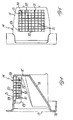
- FIG. 1 shown at 1 is the main body of a food cutting apparatus.
- an electric motor 2 comprising a main shaft 3 connected by a pair of transmission gears 4, 5 to a hub 6, to which is fixed, by a bayonet attachment 7, the cylindrical housing 8 of a rotating tool 9.
- This rotating tool 9 is positioned inside a stationary seat 19 located above the main body 1 of the apparatus and comprising a main metal blade 10 fixed to the housing 8.
- This main blade 10 projects radially from the cylindrical surface of the said housing 8, as shown in Figure 2.
- Above the rotating tool 9 and the stationary seat 19 is a hopper 11 for loading the food to be cut, which is pushed and pressed towards a loading mouth 12 by a pressing block 13.
- Another, stationary cutting device 14 is inserted inside the housing 8 of this rotating tool 9 and comprises at the top an essentially cylindrical body 15 and at the bottom an inclined sliding surface 16 for the cut food leading towards a discharge mouth 17.
- the cutting device 14 comprises a part 18 designed to clip onto a projecting edge 20 of the stationary seat 19 located above the main body 1.
- the upper cylindrical body 15 of the said cutting device 14 comprises an arcuate support 21 to which are fixed a series of essentially vertical blades 22.
- FIG. 2 is a front view of the cutting device 14 fitted inside the cylindrical housing 8 of the rotating tool 9.
- This housing 8 includes an upper opening 23 to whose edges there are fixed on the one hand, on the left when viewing the figure, the radially projecting main blade 10 and, on the other hand, on the right when viewing the figure, a support plate 24 for a series of cutters 25 arranged essentially in a direction that is perpendicular to the surface of the cylindrical housing 8 and in front of the main blade 10, with reference to the direction of rotation of the tool 9 indicated in the figure by the arrow R.
- the housing 8 is made of plastic by injection moulding, this main blade 10 and this support plate 24 may be inserted into the said housing 8 during moulding. Otherwise, they may be fitted at a later stage.
- this cylindrical body 15 comprises an upper opening 26 to which is fixed the support for the blades 22, the latter being arranged in an essentially vertical direction, that is parallel to the axis of rotation of the tool 9 and perpendicular to the cutters 25.
- These blades 22 are in front of the loading mouth 12 at the bottom end of the hopper 11, into which the food 27 to be cut is inserted and pushed against the rotating tool 9 by the pressing block 13.
- Figures 2 and 3 show two successive stages in the operation of the present apparatus: when the tool 9 is turned by the electric motor 2 the cutters 25 initially cut into the bottom of the food 27 and the main blade 10 then cuts the said food 27 into a series of sticks 28, one of which can be seen in the figure. Note that these cutters may all be arranged along the same directrix of the cylindrical housing 8 and hence of the associated support plate 24, or may be offset from each other, as shown in Figure 3.
- the main blade 10 forces the sticks 28 down onto the blades 22 of the cutting device, which is in a stationary position, with the result that the sticks 28 are additionally cut at right angles to their length, thus giving dice which pass through the support 21 of the said blades 22 and slide down the lower inclined surface 16 to the discharge mouth 17, shown in Figure 1.
- the present apparatus can still be used to efficiently cut the food 27 into sticks: in this situation, as it rotates, the said main blade 10 will cut the said food 27 into slices which will be pushed against the blades 22 of the stationary device 14, thus producing sticks which will fall towards the discharge mouth 17 down the inclined surface 16.
Landscapes
- Life Sciences & Earth Sciences (AREA)
- Forests & Forestry (AREA)
- Engineering & Computer Science (AREA)
- Mechanical Engineering (AREA)
- Food-Manufacturing Devices (AREA)
- Formation And Processing Of Food Products (AREA)
- Preparation Of Fruits And Vegetables (AREA)
Abstract
Description
- The present invention relates to a food cutting apparatus, particularly for cutting loose food such as vegetables, fruit, cheese or the like.
- As is known, there are in existence apparatuses for cutting food into slices, consisting of a main body housing an electric motor connected, by suitable transmission components, to a tool rotating in front of a loading mouth for the food to be cut, comprising a cylindrical housing provided with a main blade projecting radially from the outer surface of the said housing. With this main blade it is possible to cut food into slices, while by adding to the said cylindrical housing a series of cutters in front of the said blade, it is possible to cut the food into sticks.
- Among the major drawbacks of these apparatuses is the fact that it is impossible to cut food into shapes other than sticks or slices, so the object of the present invention is to provide an apparatus capable of cutting food into other shapes as well, such as dice or the like, and that will significantly increase the efficiency of stick cutting, by combining the rotating tool with a stationary and interchangeable device.
- From DE-B-10 48 393 a food cutting apparatus is known comprising a main body provided with drive means connected, by suitable transmission components, to a rotating tool comprising a housing of essentially cylindrical shape in front of a loading mouth for the food that is to be cut and provided with at least one main blade that projects radially from the outer surface of the said housing; this apparatus comprises cutting means in the form of a cutting grate cooperating with this main blade of the tool to give the cut food the shape of cubes or dices.
- The main drawback of the above prior art device resides in the fact that it occours very often that part of the cubes or dices thus formed remain entrapped into the said cutting grate.
- It is therefore the main object of the present invention a food cutting apparatus which is capable to obviate to the above drawback of the prior art cutting appartuses.
- The above object is obtained by an apparatus according to claim 1.
- Other objects and advantages of the present invention will be understood more fully on perusing the following description, taken by way of non-restrictive example, with reference to the appended drawings in which:
- Figure 1 is a side view, partly in section, of a food cutting apparatus according to the present invention;
- Figure 2 is a partial front view in cross section of a food dicing device inserted into the apparatus shown in Figure 1 and illustrated at an intermediate stage of operation, and
- Figure 3 is a partial front view in cross section of the device shown in Figure 2 at a later stage of operation;
- Referring to the appended drawings and in particular to Figure 1 of these, shown at 1 is the main body of a food cutting apparatus. Housed inside this main body 1 is an electric motor 2 comprising a
main shaft 3 connected by a pair of transmission gears 4, 5 to ahub 6, to which is fixed, by abayonet attachment 7, thecylindrical housing 8 of a rotatingtool 9. This rotatingtool 9 is positioned inside astationary seat 19 located above the main body 1 of the apparatus and comprising amain metal blade 10 fixed to thehousing 8. Thismain blade 10 projects radially from the cylindrical surface of the saidhousing 8, as shown in Figure 2. Above the rotatingtool 9 and thestationary seat 19 is a hopper 11 for loading the food to be cut, which is pushed and pressed towards aloading mouth 12 by apressing block 13. Another,stationary cutting device 14 is inserted inside thehousing 8 of thisrotating tool 9 and comprises at the top an essentiallycylindrical body 15 and at the bottom an inclined slidingsurface 16 for the cut food leading towards adischarge mouth 17. At the lower end of the saidinclined surface 16, thecutting device 14 comprises apart 18 designed to clip onto a projectingedge 20 of thestationary seat 19 located above the main body 1. As can be seen again in Figure 1, the uppercylindrical body 15 of the saidcutting device 14 comprises anarcuate support 21 to which are fixed a series of essentiallyvertical blades 22. - Figure 2 is a front view of the
cutting device 14 fitted inside thecylindrical housing 8 of the rotatingtool 9. Thishousing 8 includes anupper opening 23 to whose edges there are fixed on the one hand, on the left when viewing the figure, the radially projectingmain blade 10 and, on the other hand, on the right when viewing the figure, asupport plate 24 for a series ofcutters 25 arranged essentially in a direction that is perpendicular to the surface of thecylindrical housing 8 and in front of themain blade 10, with reference to the direction of rotation of thetool 9 indicated in the figure by the arrow R. If thehousing 8 is made of plastic by injection moulding, thismain blade 10 and thissupport plate 24 may be inserted into the saidhousing 8 during moulding. Otherwise, they may be fitted at a later stage. As an alternative to this, furthermore, it would be possible to have severalmain blades 10 arranged around thecylindrical housing 8 at regular intervals, e.g. two diametricallyopposite blades 10 at 180° from each other. Fitted inside the saidhousing 8 are the uppercylindrical body 15 and the lowerinclined surface 16 of the cutting device: thiscylindrical body 15 comprises anupper opening 26 to which is fixed the support for theblades 22, the latter being arranged in an essentially vertical direction, that is parallel to the axis of rotation of thetool 9 and perpendicular to thecutters 25. Theseblades 22 are in front of theloading mouth 12 at the bottom end of the hopper 11, into which thefood 27 to be cut is inserted and pushed against the rotatingtool 9 by thepressing block 13. - Figures 2 and 3 show two successive stages in the operation of the present apparatus: when the
tool 9 is turned by the electric motor 2 thecutters 25 initially cut into the bottom of thefood 27 and themain blade 10 then cuts the saidfood 27 into a series ofsticks 28, one of which can be seen in the figure. Note that these cutters may all be arranged along the same directrix of thecylindrical housing 8 and hence of theassociated support plate 24, or may be offset from each other, as shown in Figure 3. During the rotation R, themain blade 10 forces thesticks 28 down onto theblades 22 of the cutting device, which is in a stationary position, with the result that thesticks 28 are additionally cut at right angles to their length, thus giving dice which pass through thesupport 21 of thesaid blades 22 and slide down the lowerinclined surface 16 to thedischarge mouth 17, shown in Figure 1. - If the
rotating tool 9 does not have thecutters 25 preceding themain blade 10, the present apparatus can still be used to efficiently cut thefood 27 into sticks: in this situation, as it rotates, the saidmain blade 10 will cut the saidfood 27 into slices which will be pushed against theblades 22 of thestationary device 14, thus producing sticks which will fall towards thedischarge mouth 17 down theinclined surface 16.
Claims (6)
- Food cutting apparatus comprising a main body (1) provided with drive means (2) connected, by suitable transmission components (3, 4, 5, 6), to a rotating tool (9) comprising a housing (8) of essentially cylindrical shape in front of a loading mouth (12) for the food (27) that is to be cut and provided with at least one main blade (10) that projects radially from the outer surface of the said housing (8) and with a cutting device (14) connected to the said main body (1) and inserted into the said housing (8) of the tool (9), the said device (14) being provided with cutting means (22) working with the said main blade (10) of the rotating tool (9) to give the cut food (27) any shape such as sticks, dice or other shapes, characterized in that the rotating tool (9) comprises a series of cutters (25) arranged in front of the main blade (10) and essentially in a direction that is perpendicular to the cylindrical housing (8) of the said tool (9), the said cutters (25) and the said main blade (10) working with the said series of blades (22) of the device (14).
- Apparatus according to Claim 1, characterized in that the said device (14) comprises an opening (26) in front of the mouth (12) through which the food (27) to be cut is loaded, the said cutting means (22) being fixed to the said opening (26) and the said main blade (10) being capable of pushing the said food (27) against the said cutting means (22.
- Apparatus according to Claim 1, characterized in that the said cutting device (14) is in a stationary position and comprises a series of blades (22) fixed to its outer surface, the said blades (22) being positioned in a direction that is essentially parallel to the axis of rotation (R) of the rotating tool (9).
- Apparatus according to any one of the preceding claims, characterized in that the said cutting device (14) comprises an essentially cylindrical upper body (15) inserted into the housing (8) of the said rotating tool (9) and fixed removably to a seat (19) provided in the main body (1) of the apparatus.
- Apparatus according to any one of the preceding claims, characterized in that the said device (14) comprises a lower inclined sliding surface (16) for the food (27), having a discharge mouth (17) for the said food (27) at its end.
- Apparatus according to Claim 4 characterized in that the said device (14) comprises a part (18) designed to clip onto a projecting edge (20) of the said stationary seat (19) provided in the main body (1) of the apparatus.
Applications Claiming Priority (3)
| Application Number | Priority Date | Filing Date | Title |
|---|---|---|---|
| ITGE20020066 | 2002-07-24 | ||
| IT2002GE000066A ITGE20020066A1 (en) | 2002-07-24 | 2002-07-24 | FOOD CUTTING APPARATUS |
| PCT/EP2003/007118 WO2004012915A1 (en) | 2002-07-24 | 2003-07-03 | Food cutting apparatus |
Publications (2)
| Publication Number | Publication Date |
|---|---|
| EP1523399A1 EP1523399A1 (en) | 2005-04-20 |
| EP1523399B1 true EP1523399B1 (en) | 2006-03-08 |
Family
ID=30130824
Family Applications (1)
| Application Number | Title | Priority Date | Filing Date |
|---|---|---|---|
| EP03740410A Expired - Lifetime EP1523399B1 (en) | 2002-07-24 | 2003-07-03 | Food cutting apparatus |
Country Status (13)
| Country | Link |
|---|---|
| US (1) | US20050204936A1 (en) |
| EP (1) | EP1523399B1 (en) |
| JP (1) | JP2006502014A (en) |
| CN (1) | CN1668425A (en) |
| AT (1) | ATE319540T1 (en) |
| AU (1) | AU2003281809A1 (en) |
| CA (1) | CA2489985A1 (en) |
| DE (1) | DE60303937T2 (en) |
| ES (1) | ES2258723T3 (en) |
| IT (1) | ITGE20020066A1 (en) |
| PT (1) | PT1523399E (en) |
| RU (1) | RU2004137287A (en) |
| WO (1) | WO2004012915A1 (en) |
Families Citing this family (12)
| Publication number | Priority date | Publication date | Assignee | Title |
|---|---|---|---|---|
| FR2897522A1 (en) | 2006-02-22 | 2007-08-24 | Seb Sa | Food discharging accessory for e.g. slicer, has scraping unit extending from inner side of frame and provided for supplying discharging unit, where discharging unit has inclined part that is inclined towards inner edge of passage |
| FR2935285B1 (en) | 2008-09-02 | 2011-02-18 | Seb Sa | CONTINUOUS FOOD CUTTING ELECTRICAL APPLIANCE WITH SIMPLIFIED TOOL ASSEMBLY |
| RU2402248C2 (en) * | 2008-12-30 | 2010-10-27 | Анатолий Деонисович Кычаков | Device for production of extruded food product in shape of cubes |
| FR2963548B1 (en) | 2010-08-06 | 2012-08-31 | Seb Sa | FOOD CUTTING ACCESSORIES WITH IMPROVED EXCELLENCE AND HOUSEHOLD APPLIANCE COMPRISING SUCH ACCESSORIES |
| WO2014067489A1 (en) * | 2012-11-05 | 2014-05-08 | 北京银河星辰科技有限公司 | Rotary cutting type food processor |
| FR3015211B1 (en) | 2013-12-20 | 2016-01-29 | Seb Sa | DEVICE FOR FRAGMENTATION OF FOOD AND EJECTION OF FRAGMENTED FOODS |
| US9878462B2 (en) * | 2014-02-12 | 2018-01-30 | Gea Food Solutions Germany Gmbh | Interleaving paper |
| CN104552410B (en) * | 2015-01-23 | 2017-01-25 | 中山市峻国电器有限公司 | a dicer |
| CN106863413A (en) * | 2017-04-07 | 2017-06-20 | 朱九维 | One kind cuts food materials device |
| CN208629506U (en) * | 2018-08-10 | 2019-03-22 | 宁波金舜家居用品有限公司 | Food cutting device |
| CN114080308B (en) * | 2019-07-09 | 2024-12-13 | 兰博韦斯顿有限责任公司 | Hydraulic mechanical cutter |
| CN111702841B (en) * | 2020-06-20 | 2022-09-13 | 长沙市庆湘蔬菜食品开发有限公司 | Food cutting device |
Family Cites Families (14)
| Publication number | Priority date | Publication date | Assignee | Title |
|---|---|---|---|---|
| BE559308A (en) * | ||||
| DE1048393B (en) * | 1959-01-08 | |||
| US1114411A (en) * | 1912-02-27 | 1914-10-20 | Stephen T Stuver | Shredding-machine. |
| US2271175A (en) * | 1938-12-30 | 1942-01-27 | Mantelet & Boucher | Portable rotary grater |
| US2487597A (en) * | 1946-09-13 | 1949-11-08 | Archer M Sampson | Rotary disk shaver with axially manually fed pusher |
| DE1141758B (en) * | 1959-02-11 | 1962-12-27 | Gebhard Satzinger | Food slicer |
| FR2230320B3 (en) * | 1973-05-23 | 1976-05-14 | Moulinex Sa | |
| US4081145A (en) * | 1977-04-18 | 1978-03-28 | Diker-Moe Associates | Food cutting machine |
| US4214715A (en) * | 1978-08-15 | 1980-07-29 | M. H. Graham Corporation | Rotary food cutting apparatus |
| US4219165A (en) * | 1978-10-10 | 1980-08-26 | Saladmaster, Inc. | Attachment for food cutters |
| US4227656A (en) * | 1978-12-22 | 1980-10-14 | Hobart Corporation | Vegetable slicer |
| US4884755A (en) * | 1988-08-30 | 1989-12-05 | Presto Industries, Inc. | Food processor |
| US5148995A (en) * | 1991-08-01 | 1992-09-22 | Hurst Richard F | Apparatus for decomposting compressed tablets |
| US5660341A (en) * | 1996-02-15 | 1997-08-26 | The Pampered Chef, Ltd. | Rotary grater |
-
2002
- 2002-07-24 IT IT2002GE000066A patent/ITGE20020066A1/en unknown
-
2003
- 2003-07-03 CN CNA038167131A patent/CN1668425A/en active Pending
- 2003-07-03 EP EP03740410A patent/EP1523399B1/en not_active Expired - Lifetime
- 2003-07-03 DE DE60303937T patent/DE60303937T2/en not_active Expired - Fee Related
- 2003-07-03 CA CA002489985A patent/CA2489985A1/en not_active Abandoned
- 2003-07-03 RU RU2004137287/02A patent/RU2004137287A/en not_active Application Discontinuation
- 2003-07-03 PT PT03740410T patent/PT1523399E/en unknown
- 2003-07-03 US US10/518,853 patent/US20050204936A1/en not_active Abandoned
- 2003-07-03 JP JP2004525145A patent/JP2006502014A/en active Pending
- 2003-07-03 AT AT03740410T patent/ATE319540T1/en not_active IP Right Cessation
- 2003-07-03 AU AU2003281809A patent/AU2003281809A1/en not_active Abandoned
- 2003-07-03 ES ES03740410T patent/ES2258723T3/en not_active Expired - Lifetime
- 2003-07-03 WO PCT/EP2003/007118 patent/WO2004012915A1/en not_active Ceased
Also Published As
| Publication number | Publication date |
|---|---|
| DE60303937D1 (en) | 2006-05-04 |
| PT1523399E (en) | 2006-06-30 |
| US20050204936A1 (en) | 2005-09-22 |
| CA2489985A1 (en) | 2004-02-12 |
| EP1523399A1 (en) | 2005-04-20 |
| ES2258723T3 (en) | 2006-09-01 |
| CN1668425A (en) | 2005-09-14 |
| DE60303937T2 (en) | 2006-10-26 |
| WO2004012915A1 (en) | 2004-02-12 |
| AU2003281809A1 (en) | 2004-02-23 |
| ITGE20020066A1 (en) | 2004-01-26 |
| RU2004137287A (en) | 2005-07-20 |
| JP2006502014A (en) | 2006-01-19 |
| ATE319540T1 (en) | 2006-03-15 |
Similar Documents
| Publication | Publication Date | Title |
|---|---|---|
| EP1523399B1 (en) | Food cutting apparatus | |
| US6460444B2 (en) | Rotary apparatus for cutting a food product | |
| CN205129974U (en) | Electronic section device that shreds | |
| KR101948370B1 (en) | Device for extracting beverage juices | |
| CS244832B2 (en) | Cutter | |
| WO2017070214A1 (en) | Food processor spiral cutting attachment | |
| WO2010082857A1 (en) | Multifunctional kitchen appliance | |
| CN206780477U (en) | A kind of root leaf dual-purpose multifunctional vegetable-chopper | |
| US20070252024A1 (en) | Reciprocating blade and circumferentially driven blade food preparation device | |
| JPH0547357B2 (en) | ||
| ES8502017A1 (en) | Electric household appliance for cutting fruit, vegetables and similar food products into small sticks or chunks of variable thickness. | |
| AU650129B2 (en) | Meat slicing apparatus | |
| US2138262A (en) | Cutting machine | |
| KR100881216B1 (en) | Cutting knife for high speed meat cutting machine and high speed meat cutting machine comprising same | |
| US12202162B2 (en) | Motorised food-processor apparatus | |
| CN212212536U (en) | Full-automatic bone sawing machine | |
| CN111113517B (en) | Garlic slice production equipment | |
| KR101025646B1 (en) | Bean Sprout Root Cutting Device | |
| US2442210A (en) | Machine for dicing food products | |
| KR20130141828A (en) | Vegetable sliced cut | |
| KR100642833B1 (en) | Automatic adjustment of blade engagement intervals | |
| CA2225776A1 (en) | Machine for slicing sausage or the like | |
| EP0729711A1 (en) | Device for cutting the calyx and the stem of hortofruit culture products | |
| KR200436991Y1 (en) | Vegetable seasoning machine | |
| CN205727936U (en) | Throw and the food preparation device including this throw |
Legal Events
| Date | Code | Title | Description |
|---|---|---|---|
| PUAI | Public reference made under article 153(3) epc to a published international application that has entered the european phase |
Free format text: ORIGINAL CODE: 0009012 |
|
| 17P | Request for examination filed |
Effective date: 20050113 |
|
| AK | Designated contracting states |
Kind code of ref document: A1 Designated state(s): AT BE BG CH CY CZ DE DK EE ES FI FR GB GR HU IE IT LI LU MC NL PT RO SE SI SK TR |
|
| AX | Request for extension of the european patent |
Extension state: AL LT LV MK |
|
| GRAP | Despatch of communication of intention to grant a patent |
Free format text: ORIGINAL CODE: EPIDOSNIGR1 |
|
| DAX | Request for extension of the european patent (deleted) | ||
| GRAS | Grant fee paid |
Free format text: ORIGINAL CODE: EPIDOSNIGR3 |
|
| GRAA | (expected) grant |
Free format text: ORIGINAL CODE: 0009210 |
|
| AK | Designated contracting states |
Kind code of ref document: B1 Designated state(s): AT BE BG CH CY CZ DE DK EE ES FI FR GB GR HU IE IT LI LU MC NL PT RO SE SI SK TR |
|
| PG25 | Lapsed in a contracting state [announced via postgrant information from national office to epo] |
Ref country code: BE Free format text: LAPSE BECAUSE OF FAILURE TO SUBMIT A TRANSLATION OF THE DESCRIPTION OR TO PAY THE FEE WITHIN THE PRESCRIBED TIME-LIMIT Effective date: 20060308 Ref country code: CH Free format text: LAPSE BECAUSE OF FAILURE TO SUBMIT A TRANSLATION OF THE DESCRIPTION OR TO PAY THE FEE WITHIN THE PRESCRIBED TIME-LIMIT Effective date: 20060308 Ref country code: NL Free format text: LAPSE BECAUSE OF FAILURE TO SUBMIT A TRANSLATION OF THE DESCRIPTION OR TO PAY THE FEE WITHIN THE PRESCRIBED TIME-LIMIT Effective date: 20060308 Ref country code: SK Free format text: LAPSE BECAUSE OF FAILURE TO SUBMIT A TRANSLATION OF THE DESCRIPTION OR TO PAY THE FEE WITHIN THE PRESCRIBED TIME-LIMIT Effective date: 20060308 Ref country code: SI Free format text: LAPSE BECAUSE OF FAILURE TO SUBMIT A TRANSLATION OF THE DESCRIPTION OR TO PAY THE FEE WITHIN THE PRESCRIBED TIME-LIMIT Effective date: 20060308 Ref country code: FI Free format text: LAPSE BECAUSE OF FAILURE TO SUBMIT A TRANSLATION OF THE DESCRIPTION OR TO PAY THE FEE WITHIN THE PRESCRIBED TIME-LIMIT Effective date: 20060308 Ref country code: LI Free format text: LAPSE BECAUSE OF FAILURE TO SUBMIT A TRANSLATION OF THE DESCRIPTION OR TO PAY THE FEE WITHIN THE PRESCRIBED TIME-LIMIT Effective date: 20060308 Ref country code: RO Free format text: LAPSE BECAUSE OF FAILURE TO SUBMIT A TRANSLATION OF THE DESCRIPTION OR TO PAY THE FEE WITHIN THE PRESCRIBED TIME-LIMIT Effective date: 20060308 Ref country code: AT Free format text: LAPSE BECAUSE OF FAILURE TO SUBMIT A TRANSLATION OF THE DESCRIPTION OR TO PAY THE FEE WITHIN THE PRESCRIBED TIME-LIMIT Effective date: 20060308 |
|
| REG | Reference to a national code |
Ref country code: GB Ref legal event code: FG4D |
|
| REG | Reference to a national code |
Ref country code: CH Ref legal event code: EP |
|
| REG | Reference to a national code |
Ref country code: IE Ref legal event code: FG4D |
|
| REF | Corresponds to: |
Ref document number: 60303937 Country of ref document: DE Date of ref document: 20060504 Kind code of ref document: P |
|
| PG25 | Lapsed in a contracting state [announced via postgrant information from national office to epo] |
Ref country code: SE Free format text: LAPSE BECAUSE OF FAILURE TO SUBMIT A TRANSLATION OF THE DESCRIPTION OR TO PAY THE FEE WITHIN THE PRESCRIBED TIME-LIMIT Effective date: 20060608 Ref country code: DK Free format text: LAPSE BECAUSE OF FAILURE TO SUBMIT A TRANSLATION OF THE DESCRIPTION OR TO PAY THE FEE WITHIN THE PRESCRIBED TIME-LIMIT Effective date: 20060608 Ref country code: BG Free format text: LAPSE BECAUSE OF FAILURE TO SUBMIT A TRANSLATION OF THE DESCRIPTION OR TO PAY THE FEE WITHIN THE PRESCRIBED TIME-LIMIT Effective date: 20060608 |
|
| PGFP | Annual fee paid to national office [announced via postgrant information from national office to epo] |
Ref country code: FR Payment date: 20060609 Year of fee payment: 4 |
|
| REG | Reference to a national code |
Ref country code: PT Ref legal event code: SC4A Effective date: 20060505 |
|
| PG25 | Lapsed in a contracting state [announced via postgrant information from national office to epo] |
Ref country code: IE Free format text: LAPSE BECAUSE OF NON-PAYMENT OF DUE FEES Effective date: 20060703 |
|
| PG25 | Lapsed in a contracting state [announced via postgrant information from national office to epo] |
Ref country code: MC Free format text: LAPSE BECAUSE OF NON-PAYMENT OF DUE FEES Effective date: 20060731 |
|
| NLV1 | Nl: lapsed or annulled due to failure to fulfill the requirements of art. 29p and 29m of the patents act | ||
| REG | Reference to a national code |
Ref country code: ES Ref legal event code: FG2A Ref document number: 2258723 Country of ref document: ES Kind code of ref document: T3 |
|
| PGFP | Annual fee paid to national office [announced via postgrant information from national office to epo] |
Ref country code: DE Payment date: 20060902 Year of fee payment: 4 |
|
| REG | Reference to a national code |
Ref country code: CH Ref legal event code: PL |
|
| ET | Fr: translation filed | ||
| PLBE | No opposition filed within time limit |
Free format text: ORIGINAL CODE: 0009261 |
|
| STAA | Information on the status of an ep patent application or granted ep patent |
Free format text: STATUS: NO OPPOSITION FILED WITHIN TIME LIMIT |
|
| 26N | No opposition filed |
Effective date: 20061211 |
|
| PG25 | Lapsed in a contracting state [announced via postgrant information from national office to epo] |
Ref country code: PT Free format text: LAPSE BECAUSE OF NON-PAYMENT OF DUE FEES Effective date: 20070403 |
|
| REG | Reference to a national code |
Ref country code: PT Ref legal event code: MM4A Free format text: LAPSE DUE TO NON-PAYMENT OF FEES Effective date: 20070403 |
|
| REG | Reference to a national code |
Ref country code: ES Ref legal event code: FD2A Effective date: 20060704 |
|
| PG25 | Lapsed in a contracting state [announced via postgrant information from national office to epo] |
Ref country code: ES Free format text: LAPSE BECAUSE OF NON-PAYMENT OF DUE FEES Effective date: 20060704 |
|
| GBPC | Gb: european patent ceased through non-payment of renewal fee |
Effective date: 20070703 |
|
| PG25 | Lapsed in a contracting state [announced via postgrant information from national office to epo] |
Ref country code: GR Free format text: LAPSE BECAUSE OF FAILURE TO SUBMIT A TRANSLATION OF THE DESCRIPTION OR TO PAY THE FEE WITHIN THE PRESCRIBED TIME-LIMIT Effective date: 20060609 Ref country code: CZ Free format text: LAPSE BECAUSE OF FAILURE TO SUBMIT A TRANSLATION OF THE DESCRIPTION OR TO PAY THE FEE WITHIN THE PRESCRIBED TIME-LIMIT Effective date: 20060308 Ref country code: DE Free format text: LAPSE BECAUSE OF NON-PAYMENT OF DUE FEES Effective date: 20080201 |
|
| PG25 | Lapsed in a contracting state [announced via postgrant information from national office to epo] |
Ref country code: GB Free format text: LAPSE BECAUSE OF NON-PAYMENT OF DUE FEES Effective date: 20070703 |
|
| REG | Reference to a national code |
Ref country code: FR Ref legal event code: ST Effective date: 20080331 |
|
| PG25 | Lapsed in a contracting state [announced via postgrant information from national office to epo] |
Ref country code: EE Free format text: LAPSE BECAUSE OF FAILURE TO SUBMIT A TRANSLATION OF THE DESCRIPTION OR TO PAY THE FEE WITHIN THE PRESCRIBED TIME-LIMIT Effective date: 20060308 |
|
| PG25 | Lapsed in a contracting state [announced via postgrant information from national office to epo] |
Ref country code: HU Free format text: LAPSE BECAUSE OF FAILURE TO SUBMIT A TRANSLATION OF THE DESCRIPTION OR TO PAY THE FEE WITHIN THE PRESCRIBED TIME-LIMIT Effective date: 20060909 Ref country code: LU Free format text: LAPSE BECAUSE OF NON-PAYMENT OF DUE FEES Effective date: 20060703 |
|
| PG25 | Lapsed in a contracting state [announced via postgrant information from national office to epo] |
Ref country code: FR Free format text: LAPSE BECAUSE OF NON-PAYMENT OF DUE FEES Effective date: 20070731 |
|
| PG25 | Lapsed in a contracting state [announced via postgrant information from national office to epo] |
Ref country code: CY Free format text: LAPSE BECAUSE OF FAILURE TO SUBMIT A TRANSLATION OF THE DESCRIPTION OR TO PAY THE FEE WITHIN THE PRESCRIBED TIME-LIMIT Effective date: 20060308 |
|
| PG25 | Lapsed in a contracting state [announced via postgrant information from national office to epo] |
Ref country code: TR Free format text: LAPSE BECAUSE OF FAILURE TO SUBMIT A TRANSLATION OF THE DESCRIPTION OR TO PAY THE FEE WITHIN THE PRESCRIBED TIME-LIMIT Effective date: 20060308 |
|
| PGFP | Annual fee paid to national office [announced via postgrant information from national office to epo] |
Ref country code: IT Payment date: 20170719 Year of fee payment: 15 |
|
| PG25 | Lapsed in a contracting state [announced via postgrant information from national office to epo] |
Ref country code: IT Free format text: LAPSE BECAUSE OF NON-PAYMENT OF DUE FEES Effective date: 20180703 |