EP1523351B1 - System for peritoneal dialysis - Google Patents
System for peritoneal dialysis Download PDFInfo
- Publication number
- EP1523351B1 EP1523351B1 EP03765631A EP03765631A EP1523351B1 EP 1523351 B1 EP1523351 B1 EP 1523351B1 EP 03765631 A EP03765631 A EP 03765631A EP 03765631 A EP03765631 A EP 03765631A EP 1523351 B1 EP1523351 B1 EP 1523351B1
- Authority
- EP
- European Patent Office
- Prior art keywords
- fluid
- dialysate
- patient
- fluid circuit
- therapy
- Prior art date
- Legal status (The legal status is an assumption and is not a legal conclusion. Google has not performed a legal analysis and makes no representation as to the accuracy of the status listed.)
- Revoked
Links
- 238000000502 dialysis Methods 0.000 title claims description 96
- 239000012530 fluid Substances 0.000 claims abstract description 264
- 238000002560 therapeutic procedure Methods 0.000 claims abstract description 110
- 238000004140 cleaning Methods 0.000 claims abstract description 27
- 210000003200 peritoneal cavity Anatomy 0.000 claims abstract description 26
- 238000004891 communication Methods 0.000 claims abstract description 6
- 238000011282 treatment Methods 0.000 claims description 78
- 239000000463 material Substances 0.000 claims description 38
- XSQUKJJJFZCRTK-UHFFFAOYSA-N Urea Chemical compound NC(N)=O XSQUKJJJFZCRTK-UHFFFAOYSA-N 0.000 claims description 31
- 239000004202 carbamide Substances 0.000 claims description 30
- WQZGKKKJIJFFOK-GASJEMHNSA-N Glucose Natural products OC[C@H]1OC(O)[C@H](O)[C@@H](O)[C@@H]1O WQZGKKKJIJFFOK-GASJEMHNSA-N 0.000 claims description 28
- 239000002357 osmotic agent Substances 0.000 claims description 27
- 239000008121 dextrose Substances 0.000 claims description 18
- DDRJAANPRJIHGJ-UHFFFAOYSA-N creatinine Chemical compound CN1CC(=O)NC1=N DDRJAANPRJIHGJ-UHFFFAOYSA-N 0.000 claims description 12
- OKTJSMMVPCPJKN-UHFFFAOYSA-N Carbon Chemical compound [C] OKTJSMMVPCPJKN-UHFFFAOYSA-N 0.000 claims description 9
- 239000003792 electrolyte Substances 0.000 claims description 8
- 229910019142 PO4 Inorganic materials 0.000 claims description 7
- 235000021317 phosphate Nutrition 0.000 claims description 7
- 229940109239 creatinine Drugs 0.000 claims description 6
- NBIIXXVUZAFLBC-UHFFFAOYSA-K phosphate Chemical compound [O-]P([O-])([O-])=O NBIIXXVUZAFLBC-UHFFFAOYSA-K 0.000 claims description 5
- 239000010452 phosphate Substances 0.000 claims description 5
- 102000015736 beta 2-Microglobulin Human genes 0.000 claims description 3
- 108010081355 beta 2-Microglobulin Proteins 0.000 claims description 3
- 239000002594 sorbent Substances 0.000 claims description 3
- 150000003013 phosphoric acid derivatives Chemical class 0.000 claims description 2
- 239000000243 solution Substances 0.000 description 50
- 239000002699 waste material Substances 0.000 description 20
- QGZKDVFQNNGYKY-UHFFFAOYSA-N Ammonia Chemical compound N QGZKDVFQNNGYKY-UHFFFAOYSA-N 0.000 description 18
- XLYOFNOQVPJJNP-UHFFFAOYSA-N water Substances O XLYOFNOQVPJJNP-UHFFFAOYSA-N 0.000 description 17
- 238000000034 method Methods 0.000 description 16
- 230000008901 benefit Effects 0.000 description 14
- 238000001631 haemodialysis Methods 0.000 description 12
- 230000000322 hemodialysis Effects 0.000 description 12
- 239000007788 liquid Substances 0.000 description 10
- 230000002503 metabolic effect Effects 0.000 description 10
- 239000003053 toxin Substances 0.000 description 10
- 231100000765 toxin Toxicity 0.000 description 10
- 108700012359 toxins Proteins 0.000 description 10
- 229910021529 ammonia Inorganic materials 0.000 description 9
- 239000011230 binding agent Substances 0.000 description 9
- 239000000470 constituent Substances 0.000 description 9
- 210000004369 blood Anatomy 0.000 description 8
- 239000008280 blood Substances 0.000 description 8
- 230000008859 change Effects 0.000 description 8
- 230000001965 increasing effect Effects 0.000 description 8
- 230000008569 process Effects 0.000 description 8
- 238000010438 heat treatment Methods 0.000 description 7
- 239000006227 byproduct Substances 0.000 description 6
- 239000003990 capacitor Substances 0.000 description 6
- 230000009977 dual effect Effects 0.000 description 6
- 238000005086 pumping Methods 0.000 description 6
- 229910052799 carbon Inorganic materials 0.000 description 5
- 230000006870 function Effects 0.000 description 5
- 210000003734 kidney Anatomy 0.000 description 5
- 210000004303 peritoneum Anatomy 0.000 description 5
- DGAQECJNVWCQMB-PUAWFVPOSA-M Ilexoside XXIX Chemical compound C[C@@H]1CC[C@@]2(CC[C@@]3(C(=CC[C@H]4[C@]3(CC[C@@H]5[C@@]4(CC[C@@H](C5(C)C)OS(=O)(=O)[O-])C)C)[C@@H]2[C@]1(C)O)C)C(=O)O[C@H]6[C@@H]([C@H]([C@@H]([C@H](O6)CO)O)O)O.[Na+] DGAQECJNVWCQMB-PUAWFVPOSA-M 0.000 description 4
- 208000001647 Renal Insufficiency Diseases 0.000 description 4
- 238000006243 chemical reaction Methods 0.000 description 4
- 230000004087 circulation Effects 0.000 description 4
- 239000007789 gas Substances 0.000 description 4
- 201000006370 kidney failure Diseases 0.000 description 4
- 230000003907 kidney function Effects 0.000 description 4
- 238000005259 measurement Methods 0.000 description 4
- 210000004379 membrane Anatomy 0.000 description 4
- 239000012528 membrane Substances 0.000 description 4
- 230000004048 modification Effects 0.000 description 4
- 238000012986 modification Methods 0.000 description 4
- OJUGVDODNPJEEC-UHFFFAOYSA-N phenylglyoxal Chemical compound O=CC(=O)C1=CC=CC=C1 OJUGVDODNPJEEC-UHFFFAOYSA-N 0.000 description 4
- 239000011734 sodium Substances 0.000 description 4
- 229910052708 sodium Inorganic materials 0.000 description 4
- OYPRJOBELJOOCE-UHFFFAOYSA-N Calcium Chemical compound [Ca] OYPRJOBELJOOCE-UHFFFAOYSA-N 0.000 description 3
- 239000011575 calcium Substances 0.000 description 3
- 229910052791 calcium Inorganic materials 0.000 description 3
- 239000000385 dialysis solution Substances 0.000 description 3
- -1 for example Substances 0.000 description 3
- 230000036541 health Effects 0.000 description 3
- 230000007246 mechanism Effects 0.000 description 3
- 230000007958 sleep Effects 0.000 description 3
- 238000012546 transfer Methods 0.000 description 3
- IJGRMHOSHXDMSA-UHFFFAOYSA-N Atomic nitrogen Chemical compound N#N IJGRMHOSHXDMSA-UHFFFAOYSA-N 0.000 description 2
- BVKZGUZCCUSVTD-UHFFFAOYSA-M Bicarbonate Chemical compound OC([O-])=O BVKZGUZCCUSVTD-UHFFFAOYSA-M 0.000 description 2
- CURLTUGMZLYLDI-UHFFFAOYSA-N Carbon dioxide Chemical compound O=C=O CURLTUGMZLYLDI-UHFFFAOYSA-N 0.000 description 2
- IAZDPXIOMUYVGZ-UHFFFAOYSA-N Dimethylsulphoxide Chemical compound CS(C)=O IAZDPXIOMUYVGZ-UHFFFAOYSA-N 0.000 description 2
- FYYHWMGAXLPEAU-UHFFFAOYSA-N Magnesium Chemical compound [Mg] FYYHWMGAXLPEAU-UHFFFAOYSA-N 0.000 description 2
- ZLMJMSJWJFRBEC-UHFFFAOYSA-N Potassium Chemical compound [K] ZLMJMSJWJFRBEC-UHFFFAOYSA-N 0.000 description 2
- 108010046334 Urease Proteins 0.000 description 2
- LEHOTFFKMJEONL-UHFFFAOYSA-N Uric Acid Chemical compound N1C(=O)NC(=O)C2=C1NC(=O)N2 LEHOTFFKMJEONL-UHFFFAOYSA-N 0.000 description 2
- TVWHNULVHGKJHS-UHFFFAOYSA-N Uric acid Natural products N1C(=O)NC(=O)C2NC(=O)NC21 TVWHNULVHGKJHS-UHFFFAOYSA-N 0.000 description 2
- 239000012141 concentrate Substances 0.000 description 2
- 239000000356 contaminant Substances 0.000 description 2
- 238000011109 contamination Methods 0.000 description 2
- 230000000694 effects Effects 0.000 description 2
- 230000008030 elimination Effects 0.000 description 2
- 238000003379 elimination reaction Methods 0.000 description 2
- 230000002255 enzymatic effect Effects 0.000 description 2
- 238000001914 filtration Methods 0.000 description 2
- 239000008103 glucose Substances 0.000 description 2
- 230000003116 impacting effect Effects 0.000 description 2
- 238000001802 infusion Methods 0.000 description 2
- 239000011777 magnesium Substances 0.000 description 2
- 229910052749 magnesium Inorganic materials 0.000 description 2
- 238000012423 maintenance Methods 0.000 description 2
- 238000012544 monitoring process Methods 0.000 description 2
- LQNUZADURLCDLV-UHFFFAOYSA-N nitrobenzene Chemical compound [O-][N+](=O)C1=CC=CC=C1 LQNUZADURLCDLV-UHFFFAOYSA-N 0.000 description 2
- 235000015097 nutrients Nutrition 0.000 description 2
- 239000011591 potassium Substances 0.000 description 2
- 229910052700 potassium Inorganic materials 0.000 description 2
- 239000000047 product Substances 0.000 description 2
- 230000001172 regenerating effect Effects 0.000 description 2
- 230000001105 regulatory effect Effects 0.000 description 2
- 230000000717 retained effect Effects 0.000 description 2
- 229940116269 uric acid Drugs 0.000 description 2
- CVOFKRWYWCSDMA-UHFFFAOYSA-N 2-chloro-n-(2,6-diethylphenyl)-n-(methoxymethyl)acetamide;2,6-dinitro-n,n-dipropyl-4-(trifluoromethyl)aniline Chemical compound CCC1=CC=CC(CC)=C1N(COC)C(=O)CCl.CCCN(CCC)C1=C([N+]([O-])=O)C=C(C(F)(F)F)C=C1[N+]([O-])=O CVOFKRWYWCSDMA-UHFFFAOYSA-N 0.000 description 1
- 241000894006 Bacteria Species 0.000 description 1
- 235000003363 Cornus mas Nutrition 0.000 description 1
- 240000006766 Cornus mas Species 0.000 description 1
- 239000004698 Polyethylene Substances 0.000 description 1
- 239000004743 Polypropylene Substances 0.000 description 1
- 239000004793 Polystyrene Substances 0.000 description 1
- 238000010521 absorption reaction Methods 0.000 description 1
- 125000002777 acetyl group Chemical group [H]C([H])([H])C(*)=O 0.000 description 1
- 230000021736 acetylation Effects 0.000 description 1
- 238000006640 acetylation reaction Methods 0.000 description 1
- 244000000022 airborne pathogen Species 0.000 description 1
- 239000007864 aqueous solution Substances 0.000 description 1
- 210000001367 artery Anatomy 0.000 description 1
- QVGXLLKOCUKJST-UHFFFAOYSA-N atomic oxygen Chemical compound [O] QVGXLLKOCUKJST-UHFFFAOYSA-N 0.000 description 1
- WQZGKKKJIJFFOK-VFUOTHLCSA-N beta-D-glucose Chemical compound OC[C@H]1O[C@@H](O)[C@H](O)[C@@H](O)[C@@H]1O WQZGKKKJIJFFOK-VFUOTHLCSA-N 0.000 description 1
- 230000017531 blood circulation Effects 0.000 description 1
- 230000036772 blood pressure Effects 0.000 description 1
- 229910002092 carbon dioxide Inorganic materials 0.000 description 1
- 239000001569 carbon dioxide Substances 0.000 description 1
- 230000005465 channeling Effects 0.000 description 1
- 239000007795 chemical reaction product Substances 0.000 description 1
- 239000012459 cleaning agent Substances 0.000 description 1
- 239000011538 cleaning material Substances 0.000 description 1
- 238000005202 decontamination Methods 0.000 description 1
- 230000003588 decontaminative effect Effects 0.000 description 1
- 238000013461 design Methods 0.000 description 1
- 238000009792 diffusion process Methods 0.000 description 1
- 201000010099 disease Diseases 0.000 description 1
- 208000037265 diseases, disorders, signs and symptoms Diseases 0.000 description 1
- 238000006073 displacement reaction Methods 0.000 description 1
- 239000003814 drug Substances 0.000 description 1
- 229940079593 drug Drugs 0.000 description 1
- 238000005516 engineering process Methods 0.000 description 1
- 230000002708 enhancing effect Effects 0.000 description 1
- 230000007613 environmental effect Effects 0.000 description 1
- 230000029142 excretion Effects 0.000 description 1
- 238000011049 filling Methods 0.000 description 1
- 238000011010 flushing procedure Methods 0.000 description 1
- 125000000524 functional group Chemical group 0.000 description 1
- 230000005484 gravity Effects 0.000 description 1
- 230000026030 halogenation Effects 0.000 description 1
- 238000005658 halogenation reaction Methods 0.000 description 1
- 230000006872 improvement Effects 0.000 description 1
- 230000001939 inductive effect Effects 0.000 description 1
- 208000015181 infectious disease Diseases 0.000 description 1
- 229910052500 inorganic mineral Inorganic materials 0.000 description 1
- 238000002386 leaching Methods 0.000 description 1
- 230000004060 metabolic process Effects 0.000 description 1
- 239000011707 mineral Substances 0.000 description 1
- FEMOMIGRRWSMCU-UHFFFAOYSA-N ninhydrin Chemical compound C1=CC=C2C(=O)C(O)(O)C(=O)C2=C1 FEMOMIGRRWSMCU-UHFFFAOYSA-N 0.000 description 1
- 229910052757 nitrogen Inorganic materials 0.000 description 1
- QJGQUHMNIGDVPM-UHFFFAOYSA-N nitrogen group Chemical group [N] QJGQUHMNIGDVPM-UHFFFAOYSA-N 0.000 description 1
- 230000003204 osmotic effect Effects 0.000 description 1
- 239000001301 oxygen Substances 0.000 description 1
- 229910052760 oxygen Inorganic materials 0.000 description 1
- 239000013618 particulate matter Substances 0.000 description 1
- 230000037361 pathway Effects 0.000 description 1
- 206010034674 peritonitis Diseases 0.000 description 1
- 239000004033 plastic Substances 0.000 description 1
- 229920003023 plastic Polymers 0.000 description 1
- 229920000573 polyethylene Polymers 0.000 description 1
- 229920000642 polymer Polymers 0.000 description 1
- 229920001155 polypropylene Polymers 0.000 description 1
- 229920002223 polystyrene Polymers 0.000 description 1
- 229920000915 polyvinyl chloride Polymers 0.000 description 1
- 239000004800 polyvinyl chloride Substances 0.000 description 1
- 238000012545 processing Methods 0.000 description 1
- 230000000135 prohibitive effect Effects 0.000 description 1
- 108090000623 proteins and genes Proteins 0.000 description 1
- 102000004169 proteins and genes Human genes 0.000 description 1
- 230000008929 regeneration Effects 0.000 description 1
- 238000011069 regeneration method Methods 0.000 description 1
- 230000029219 regulation of pH Effects 0.000 description 1
- 238000012959 renal replacement therapy Methods 0.000 description 1
- 210000005227 renal system Anatomy 0.000 description 1
- 238000009877 rendering Methods 0.000 description 1
- 230000003068 static effect Effects 0.000 description 1
- 239000000126 substance Substances 0.000 description 1
- 230000001225 therapeutic effect Effects 0.000 description 1
- 210000001519 tissue Anatomy 0.000 description 1
- 231100000331 toxic Toxicity 0.000 description 1
- 230000002588 toxic effect Effects 0.000 description 1
- 238000012549 training Methods 0.000 description 1
- 229940045136 urea Drugs 0.000 description 1
- 239000002441 uremic toxin Substances 0.000 description 1
- 210000003462 vein Anatomy 0.000 description 1
Images
Classifications
-
- A—HUMAN NECESSITIES
- A61—MEDICAL OR VETERINARY SCIENCE; HYGIENE
- A61M—DEVICES FOR INTRODUCING MEDIA INTO, OR ONTO, THE BODY; DEVICES FOR TRANSDUCING BODY MEDIA OR FOR TAKING MEDIA FROM THE BODY; DEVICES FOR PRODUCING OR ENDING SLEEP OR STUPOR
- A61M1/00—Suction or pumping devices for medical purposes; Devices for carrying-off, for treatment of, or for carrying-over, body-liquids; Drainage systems
- A61M1/14—Dialysis systems; Artificial kidneys; Blood oxygenators ; Reciprocating systems for treatment of body fluids, e.g. single needle systems for hemofiltration or pheresis
- A61M1/28—Peritoneal dialysis ; Other peritoneal treatment, e.g. oxygenation
- A61M1/282—Operational modes
- A61M1/284—Continuous flow peritoneal dialysis [CFPD]
-
- A—HUMAN NECESSITIES
- A61—MEDICAL OR VETERINARY SCIENCE; HYGIENE
- A61M—DEVICES FOR INTRODUCING MEDIA INTO, OR ONTO, THE BODY; DEVICES FOR TRANSDUCING BODY MEDIA OR FOR TAKING MEDIA FROM THE BODY; DEVICES FOR PRODUCING OR ENDING SLEEP OR STUPOR
- A61M1/00—Suction or pumping devices for medical purposes; Devices for carrying-off, for treatment of, or for carrying-over, body-liquids; Drainage systems
- A61M1/14—Dialysis systems; Artificial kidneys; Blood oxygenators ; Reciprocating systems for treatment of body fluids, e.g. single needle systems for hemofiltration or pheresis
- A61M1/16—Dialysis systems; Artificial kidneys; Blood oxygenators ; Reciprocating systems for treatment of body fluids, e.g. single needle systems for hemofiltration or pheresis with membranes
- A61M1/1654—Dialysates therefor
- A61M1/1656—Apparatus for preparing dialysates
- A61M1/166—Heating
-
- A—HUMAN NECESSITIES
- A61—MEDICAL OR VETERINARY SCIENCE; HYGIENE
- A61M—DEVICES FOR INTRODUCING MEDIA INTO, OR ONTO, THE BODY; DEVICES FOR TRANSDUCING BODY MEDIA OR FOR TAKING MEDIA FROM THE BODY; DEVICES FOR PRODUCING OR ENDING SLEEP OR STUPOR
- A61M1/00—Suction or pumping devices for medical purposes; Devices for carrying-off, for treatment of, or for carrying-over, body-liquids; Drainage systems
- A61M1/14—Dialysis systems; Artificial kidneys; Blood oxygenators ; Reciprocating systems for treatment of body fluids, e.g. single needle systems for hemofiltration or pheresis
- A61M1/16—Dialysis systems; Artificial kidneys; Blood oxygenators ; Reciprocating systems for treatment of body fluids, e.g. single needle systems for hemofiltration or pheresis with membranes
- A61M1/1694—Dialysis systems; Artificial kidneys; Blood oxygenators ; Reciprocating systems for treatment of body fluids, e.g. single needle systems for hemofiltration or pheresis with membranes with recirculating dialysing liquid
- A61M1/1696—Dialysis systems; Artificial kidneys; Blood oxygenators ; Reciprocating systems for treatment of body fluids, e.g. single needle systems for hemofiltration or pheresis with membranes with recirculating dialysing liquid with dialysate regeneration
-
- A—HUMAN NECESSITIES
- A61—MEDICAL OR VETERINARY SCIENCE; HYGIENE
- A61M—DEVICES FOR INTRODUCING MEDIA INTO, OR ONTO, THE BODY; DEVICES FOR TRANSDUCING BODY MEDIA OR FOR TAKING MEDIA FROM THE BODY; DEVICES FOR PRODUCING OR ENDING SLEEP OR STUPOR
- A61M1/00—Suction or pumping devices for medical purposes; Devices for carrying-off, for treatment of, or for carrying-over, body-liquids; Drainage systems
- A61M1/14—Dialysis systems; Artificial kidneys; Blood oxygenators ; Reciprocating systems for treatment of body fluids, e.g. single needle systems for hemofiltration or pheresis
- A61M1/28—Peritoneal dialysis ; Other peritoneal treatment, e.g. oxygenation
-
- A—HUMAN NECESSITIES
- A61—MEDICAL OR VETERINARY SCIENCE; HYGIENE
- A61M—DEVICES FOR INTRODUCING MEDIA INTO, OR ONTO, THE BODY; DEVICES FOR TRANSDUCING BODY MEDIA OR FOR TAKING MEDIA FROM THE BODY; DEVICES FOR PRODUCING OR ENDING SLEEP OR STUPOR
- A61M2202/00—Special media to be introduced, removed or treated
- A61M2202/0021—Special media to be introduced, removed or treated removed from and reintroduced into the body, e.g. after treatment
Definitions
- the present invention generally relates to systems for providing peritoneal dialysis. More specifically, the present invention relates to systems for providing continuous flow peritoneal dialysis.
- a person's renal system can fail.
- renal failure of any cause there are several physiological derangements. The balance of water, minerals and the excretion of daily metabolic load is no longer possible in renal failure.
- toxic end products of nitrogen metabolism e.g., urea, creatinine, uric acid, and others
- Kidney failure and reduced kidney function have been treated with dialysis. Dialysis removes waste, toxins and excess water from the body that would otherwise have been removed by normal functioning kidneys. Dialysis treatment for replacement of kidney functions is critical to many people because the treatment is life saving. One who has tailed kidneys could not continue to live without replacing at least the filtration functions of the kidneys.
- a large amount of dialysate for example about 90-120 liters, is used by most hemodialysis machines to dialyze the blood during a single hemodialysis therapy. The spent dialysate is then discarded. Hemodialysis treatment lasts several hours and is generally performed in a treatment center about three times per week.
- Peritoneal dialysis utilizes a sterile dialysis solution or "dialysate", which is infused into a patient's peritoneal cavity and into contact with the patient's peritoneal membrane. Waste, toxins and excess water pass from the patient's bloodstream through the peritoneal membrane and into the dialysate. The transfer of waste, toxins, and excess water from the bloodstream into the dialysate occurs due to diffusion and osmosis during a dwell period as an osmotic agent in the dialysate creates an osmotic gradient across the membrane. The spent dialysate is later drained from the patient's peritoneal cavity to remove the waste, toxins and excess water from the patient.
- Automated peritoneal dialysis is similar to continuous ambulatory peritoneal dialysis in that the dialysis treatment includes a drain, fill, and dwell cycle. However, a dialysis machine automatically performs three or more cycles of peritoneal dialysis treatment, typically overnight while the patient sleeps.
- an automated dialysis machine fluidly connects to an implanted catheter.
- the automated dialysis machine also fluidly connects to a source or bag of fresh dialysate and to a fluid drain.
- the dialysis machine pumps spent dialysate from the peritoneal cavity, through the catheter, to the drain.
- the dialysis machine then pumps fresh dialysate from the dialysate source, through the catheter, and into the patient's peritoneal cavity.
- the automated machine allows the dialysate to dwell within the cavity so that the transfer of waste, toxins and excess water from the patient's bloodstream to the dialysate solution can take place.
- a computer controls the automated dialysis machine so that the dialysis treatment occurs automatically when the patient is connected to the dialysis machine, for example, when the patient sleeps. That is, the dialysis system automatically and sequentially pumps fluid into the peritoneal cavity, allows for dwell, pumps fluid out of the peritoneal cavity, and repeats the procedure.
- CFPD Continuous flow peritoneal dialysis
- US-5,944,684 and US-6,409,699 disclose peritoneal dialysis systems that include devices for regenerating spent dialysis fluid.
- the systems should allow the patient to perform the procedure at home without the need for storing an inordinate amount of fresh dialysate bags.
- the systems should further be automated so that the procedure can be largely performed at night while the patient sleep.
- the present invention relates to systems for providing peritoneal dialysis.
- the present invention relates to continuous flow peritoneal dialysis that employs a single closed fluid path along which dialysate can be circulated into, through and out of a peritoneal cavity of a patient in order to effectively remove acceptable levels of solutes and excess water or ultrafiltrate from the patient during treatment.
- the present system includes a fluid circuit which is coupled to the patient thereby defining a tingle closed fluid path along which the dialysate can be circulated and thus reused during the entire treatment.
- the dialysate is circulated along the fluid path in a continuous manner.
- the amount of dialysate necessary for effective treatment can be optimally minimized.
- the present system can utilize six liters or less of dialysate during treatment. With this amount of reusable dialysate, effective treatment can be conducted over periods of at most 10 hours, preferably about 8 hours or less, more preferably about 7 hours or less.
- the present system Prior to reuse, the dialysate is cleaned as it circulates along the closed fluid path.
- the present system includes a cleaning device which is coupled to the closed fluid path.
- the cleaning device is capable of removing an acceptable level of solutes including uremic toxins or other metabolic waste products that have passed from the patient to the dialysate during treatment.
- the amount of solutes removed from the dialysate is necessary to maintain a diffusive gradient at a sufficient level such that solutes and ultrafiltrate can be effectively removed from the patient upon reuse of the dialysate during treatment.
- the dialysate does not necessarily have to be cleaned or regenerated to its initial fresh state prior to reuse. Rather, the dialysate, after cleaning, may retain some concentration of solutes removed from the patient, particularly urea.
- the cleaning device employs a sorbet material, such as carbon, to non-selectively remove a substantial portion of solutes from the dialysate.
- a sorbet material such as carbon
- the cleaning device includes a binder material to selectively remove urea, phosphate and/or other like solutes.
- the available volume therapy fluid can be influenced by a number of factors, such as the amount of dialysate fed into the closed fluid path, the amount of ultrafiltrate added to the closed fluid path and the amount of additional other solutions that can be added to the closed fluid path to enhance the diffusive properties of the dialysate.
- the therapy volume is controllably adjusted by the amount of dialysate that is fed into the closed fluid path in addition to the ultrafiltrate that passes from the patient into the closed fluid path during treatment.
- the volume capacity of the closed fluid path can be variably adjusted during treatment.
- the addition of ultrafiltrate to the fluid circuit in effect, increases the capacity to remove solutes by keeping the additional volume in contact with the loop. In an embodiment, about 1.5 liters or less of ultrafiltrate is utilized during therapy.
- the present system can utilize, in addition to carbon, binder or reactive materials which are capable of selectively removing specific types of solutes from the dialysate as previously discussed.
- the binder materials can be utilized to remove urea, phosphates or other desirable metabolic waste products that may be retained in the dialysate even after carbon treatment.
- the combination of non-selective and selective cleaning agents can be utilized to remove up to about 70% or greater of urea and other like constituents from the dialysate.
- An advantage of the present invention is to provide improved systems for providing dialysis therapy.
- Yet still another advantage of the present invention is to minimize treatment times while providing optimal use of the dialysate during continuous flow peritoneal dialysis.
- Yet a further advantage of the present invention is to provide improved systems for providing peritoneal dialysis that can effectively clean spent dialysate such that it can be circulated and reused during treatment in order to minimize the amount of dialysate necessary for effective treatment.
- the present invention employs a single closed fluid path along which a minimal volume of therapy fluid can be circulated such that the therapy fluid can pass into, through and out of a peritoneal cavity of a patient connected to the closed fluid path to effectively remove solutes, excess water and the like from the patient during treatment.
- the available volume of therapy fluid can include about 6 liters or less of an initial source of dialysate. It is believed that the available volume of therapy fluid can be circulated along the closed fluid path to remove solutes from the patient at or exceeding clinically acceptable solute removal standards, such as the National Kidney Foundation's DOQI levels.
- acceptable solute removal or clearance levels can be achieved over a period of 8 hours or less, preferably 7 hours or less, during treatment.
- a therapeutic level of clearances can be achieved for urea, creatinine, phosphate, ⁇ 2 microglobulin, the like and combinations thereof.
- the clearance levels can include, for example, about 2.1 per week to about 2.6 per week for urea; about 72 liters (1) /week (wk) to about 90 l/wk for creatinine; about 3.5 grams(g)/week(wk) for phosphate; about 600 milligrams (mg)/ week (wk) for ⁇ 2 microglobulin, the like and combinations thereof.
- the clearance levels can be determined in any suitable way.
- the urea clearance levels can be based on Kt/V calculations.
- Kt/V is generally recognized in the art as a dimensionless index that corresponds to urea clearance.
- the term "continuous flow” or other like terms as applied to dialysis therapy, such as peritoneal dialysis, means that the therapy fluid including dialysate is constantly and simultaneously flowing into and out of the patient's peritoneum during treatment.
- the dwell period of the dialysate inside the peritoneum associated with typical peritoneal dialysis therapies, such as CAPD and APD, is effectively eliminated.
- the therapy fluid is circulated in a continuous manner during treatment.
- fluid flow in the system of the present invention can include any suitable level of intermittent, non-continuous batch, tidal and/or other like fluid flow in addition to continuous flow during treatment.
- the present system may provide for brief intermittent fluid flow, such as during the filling of a pump chamber, the fluid loop, the patient and/or the like prior to treatment, brief periods of downtime or breaks in therapy and/or other like suitable conditions.
- the present system can be controlled to provide a variety and number of suitable dialysis therapies, as desired.
- the continuous flow into, though and out of the peritoneal cavity preferably occurs during the main therapy treatment, so that a dwell during a last bag, for example, does not detract from the continuous flow feature.
- dialysate does not necessarily have to be cleaned or regenerated to its original fresh state prior to reuse. Rather, the dialysate, after cleaning, may retain some concentration of solutes that was removed from the patient during therapy. This is particularly relevant to the removal of urea or other like solutes.
- the present system can controllably minimize, circulate and clean the available volume of therapy fluid during the entire treatment.
- the available volume of therapy fluid can be controllably adjusted based on a number of parameters, such as the amount of initial source of dialysate pumped into the closed fluid path, the amount of ultrafiltrate added to the closed fluid path, the amount of additional other solutions that include osmotic agents and/or other suitable constituents to enhance the diffusive properties of the dialysate, and other like parameters as described in detail below.
- the available volume of therapy fluid necessary for effective treatment can also be influenced by the efficiency of the cleaning process.
- carbon or other like materials can be utilized to clean the dialysate as it circulates long the closed fluid path.
- the cleaning efficiency can be increased with the use of materials that can selectively remove solutes in combination with the non-selective removal capabilities of carbon or other like materials. This can be performed without the use of an enzymatic conversion process that produces reaction by-products, such as the conversion of urea into ammonia, thus effectively eliminating the need to remove the by-products from the solution prior to reuse.
- the dialysis systems of the present invention provide advantages, it is believed, compared to existing dialysis systems and therapies, such as clinical advantages, economic advantages, and quality of life advantages, for example. It is believed that the present system has clinical advantages, such as, improved blood pressure control, improved fluid volume control, improved therapy performance as assessed by known clinical standards, such as the National Kidney Foundation's DOQI standard, higher clearance efficiency rates, lower glucose absorption, glucose profiling and ultrafiltrate management, reduced catheter channeling and/or the like.
- the continuous flow peritoneal dialysis therapy system of the present invention can include a variety of different components and configurations to effectively remove solutes from the patient with a minimal volume of therapy fluid and within an optimal time frame as previously discussed.
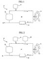
- the present system includes a fluid circuit 10 in fluid communication with a catheter 12 insertable within a patient 14 undergoing peritoneal dialysis. This defines a single closed fluid path 16 along which dialysate can be fed into and circulated, preferably in a continuous manner, to remove excess water and solutes including toxins and metabolic waste and the like from the patient as the dialysate passes into, through and out of the peritoneal cavity of the patient.
- a dual lumen catheter can be used.
- the dual lumen catheter provides for circulation of the therapy fluid along the fluid path allowing flow into, through and out of the peritoneal cavity of the patient.
- the dual lumen catheter is implanted in the patient.
- An example of a catheter for use in the dialysis system of the present invention is disclosed in U.S. Patent No. 6,976,973 filed on October 12, 2000 , and entitled "Peritoneal Dialysis Catheter.”
- two single lumen catheters can be used as long as there is an inflow and outflow path for circulation of fluid through the peritoneum.
- the fresh or initial source of dialysate can include any suitable amount and type of solution that can be effectively used to dialyze a patient.
- the present system can meet and/or exceed clinically acceptable solute removal levels while utilizing a minimal volume of therapy fluid.
- the volume of dialysate used during therapy is about 6 liters or less. It is believed that the lower range limit of the volume of dialysate can reach volume levels as low as about 5 liters or even lower as the cleaning efficiency of the dialysate in circulation along the closed fluid path is increased.
- the dialysate solution can be fed into the closed fluid path in a variety of suitable ways.
- the entire volume of the fresh source of dialysate is fed into the closed fluid loop at the beginning of therapy. This can be performed by any suitable pumping mechanism.
- the entire volume can be contained in and fed from one or more suitable solution containers 18, such as conventional dialysis solution bags that are about 6 liters in capacity.
- the dialysate can be generated and fed from an on-line dialysate generation system.
- the dialysate can be intermittently and/or continuously fed into closed fluid path during the entire therapy at any suitable flow rates and/or amounts.
- the dialysate solution can include any suitable type of dialysate solution.
- the fresh source of dialysate solution includes an osmotic agent, such as dextrose or the like in any suitable amount.
- the amount of dextrose necessary for effective therapy may vary from patient to patient.
- the amount of osmotic agent can vary and include any clinically acceptable level, such as about 1.5% by weight, about 2.5% by weight, about 3.5% by weight, about 4.25% by weight or greater to meet the specific needs of the patient.
- the dialysate can include any suitable amount and type of electrolytes in addition to the osmotic agent including, for example, calcium, sodium, potassium, like constituents and combinations thereof.
- the present system can include any suitable type of device 20 which utilizes any suitable amount and type of material to effectively clean the therapy fluid as it circulates along the closed fluid path. This facilitates the reuse of the therapy fluid to remove effective levels of solutes, excess water and the like from the patient during therapy.
- the cleaning device includes a material that is capable of non-selective removal of solutes from the therapy fluid that have been removed from the patient during therapy.
- the material includes any suitable sorbent material, such as carbon, activated carbon and/or other like material that is contained within a suitable housing, such as a cartridge, in any acceptable manner.
- the present system can include other materials in addition to those types of materials which can non-selectively remove solutes from the dialysate.
- the additional other materials include, for example, materials that can selectively remove certain solutes or the like from solution.
- the additional materials include a binder material capable of selectively removing urea, a binder material capable of selectively removing phosphate and/or the like.
- the binder materials chemically bind the solutes, such as urea, to remove them from the dialysate or other suitable fluid medium as described below in greater detail.
- This process does not result in the release of harmful substances as reaction by-products as compared to an ezymatic process.
- urease is known to enzymatically convert urea into ammonia.
- ammonia must then be removed from the dialysate prior to reintroduction into the peritoneal cavity in order to ensure the health and safety of the patient.
- the dialysate can be reintroduced into the peritoneal cavity without further processing of the dialysate as a result of the binder process.
- the use of materials capable of selective removal of solutes, particularly urea can be used to enhance the cleaning efficiency of the system of the present invention such that less therapy volume would be needed to provide effective therapy.
- the materials that can selectively remove solutes from solution can include a variety of suitable and different materials including, for example, polymeric materials that are capable of removing nitrogen-containing compounds, such as urea, creatinine, other like metabolic waste and/or the like in solution.
- these types of materials contain a functional group(s) that chemically binds with urea or other like solutes.
- U.S. Patent Nos. 3,933,753 and 4,012,317 disclose alkenylaromatic polymers containing phenylglyoxal that can function to chemically bind urea.
- the phenylglyoxal polymeric material is made via acetylation performed in, for example, nitrobenzene followed by halogenation of the acetyl group and treatment with dimethylsulfoxide as disclosed in U.S. Patent Nos. 3,933,753 and 4,012,317 .
- Another example of a polymeric material that is capable of selectively removing solutes, such as urea, from solution includes polymeric materials that contain a tricarbonyl functionality commonly known as ninhydrin as disclosed in U.S. Patent No. 4,897,200 .
- the present system can include any suitable type of material or combinations thereof to selectively remove solutes, such as urea, from solution as previously discussed.
- the therapy fluid including the dialysate
- the therapy fluid can be circulated at any acceptable flow rate.
- the fluid flow rate in the closed fluid loop can be varied up to about 300 ml/min, preferably about 100 ml/min or less.
- the present system can provide effective treatment to the patient in 8 hours or less, preferably 7 hours or less.
- the systems of the present invention are operable during the night.
- the treatment therapy is combined with an all day dwell period where a suitable amount of dialysate has dwelled within the patient.
- the all day dwell includes about 2 liters or less of dialysate. It should be appreciated that this volume can vary from patient to patient depending on the specific needs of the patient.
- the peritoneal dialysis can be performed in a variety of suitable manners.
- the entire volume of the fresh source of dialysate can be fed into the fluid circuit at the beginning of the treatment.
- the peritoneal cavity of the patient is filled with about 3 liters of the fresh source of dialysate solution and the remaining portion of the dialysate is pumped into the fluid circuit before the dialysate is circulated during treatment.
- the initial fill volume of dialysate within the patient's peritoneal cavity may vary from patient to patient.
- the treatment period can be performed over a number of treatment cycles.
- the treatment period can include two separate treatment cycles.
- the fresh source of dialysate can be pumped into and circulated along the fluid circuit and drained from the fluid circuit after each treatment cycle with the use of a device which is commonly known in the art as a cycler (not shown).
- a cycler refers to a pressure driven, diaphragm-type volumetric displacement pump coupled to a fluid path or paths in any suitable manner such that fluid flow can be automatically controlled.
- the cycler can determine the volume of liquid delivered as the difference in the volume of a pumping chamber before and after a pumping stroke.
- the pumping chamber in general, includes two parts separated by a flexible diaphragm with air on one side and fluid on the other. Increasing the air pressure pushes liquid out of the chamber expanding the volume on the air side.
- the cycler can include any suitable number and types of components, such as pumps and valves, coupled to any suitably designed fluid circuit to provide efficient and effective automatic control of therapy fluid flowing into and out of the closed fluid path 16.
- the cyclers typically applied during automated peritoneal dialysis and suitable modifications thereof can be employed.
- Patent No. 5,474,683 "Improved User Interface and Monitoring Functions for Automated Peritoneal Dialysis," filed March 3,1993, Serial No. 08/025,531 , issued as U.S. Patent No. 5,438,510 ; "Improved User Interface for Automated Peritoneal Dialysis Systems,” filed March 3, 1993, Serial No. 08/025,547 , issued as U.S. Patent No. 5,324,422 ; and "Peritoneal Dialysis Cycler,” filed March 3, 1993, Serial No. 08/006,426 , issued as U.S. Patent No. D 351,470 .
- the cycler can be coupled to the continuous flow system in any suitable manner, such as with the use of any suitable disposable cartridge that can be used as a fluid interface between the patient and the fluid circuit to readily and easily couple the patient to the fluid circuit as typically employed during automated peritoneal dialysis and/or modifications thereof.
- the therapy fluid is removed from the fluid circuit through a discharge path 22 which is coupled to the fluid circuit.
- the therapy fluid can be discharged in any suitable manner, such as by any suitable pump mechanism coupled to the fluid discharge path.
- the discharged therapy fluid can be disposed of or alternatively can be regenerated for prior use.
- the present invention can include a source of fluid 28 in addition to the dialysate and the ultrafiltrate which can be added to the fluid circuit during treatment.
- the additional fluid source can include one or more solutions, such as an aqueous solution that contains an osmotic agent, such as dextrose or the like, in a sufficient amount in order to replenish the diffusive properties of the therapy fluid during treatment.
- the amount of osmotic agent can include about 2.5% by weight, about 3.5% by weight, about 4.25% or greater by weight of the suitable amounts and combinations thereof.
- the additional solution source can also include an acceptable level and type of other constituents, such as electrolytes including calcium, magnesium, sodium, the like and combinations thereof, in addition to the osmotic agent.
- the amount of osmotic agent solution added to the fluid circuit is about 3 liters or less, preferably about 2 liters or less.
- the osmotic agent solution can be continuously fed or intermittently fed into the closed fluid path on a monitored basis in any suitable manner.
- the amount and type of osmotic agent solution necessary to facilitate effective treatment can vary from patient to patient
- a solution with a relatively high level of osmotic agent and electrolytes as compared to the existing therapy fluid can be fed to the fluid circuit in volumetric amounts of about 1 liter or less.
- the solution concentrate of osmotic agent and electrolytes can include an osmotic agent, such as dextrose, at about 4.25% or greater by weight and concentration levels of electrolytes that are higher than existing levels in the therapy solution such that levels in the therapy solution can be adjusted to achieve optimal and physiological acceptable levels prior to reuse.
- components of the solution concentrate can be individually infused into the fluid circuit.
- the components can include those types of constituents typically contained in dialysate solutions including, for example, an osmotic agent, such as dextrose, bicarbonate, sodium, calcium, magnesium, like constituents and combinations thereof.
- an osmotic agent such as dextrose, bicarbonate, sodium, calcium, magnesium, like constituents and combinations thereof.
- the amount of individual components fed into the fluid circuit can be regulated and controlled in any suitable manner.
- a sensing device can be coupled to the system of the present invention which can be utilized to provide on-line and real-time monitoring of the specific levels of the components during treatment.
- the sensor can then be configured to communicate with the infusion device (not shown) of each of the components to regulate the flow of components into the fluid circuit. This can also be utilized to monitor the level of ultrafiltrate removed from the patient. If more ultrafiltrate is desired, the sensor can be adapted to communicate with a pump to increase the flow of dextrose and thus, increase ultrafiltrate removal from the patient.
- the amount of the individual components added during therapy can be regulated based on customized therapy profiles associated with each of the components.
- the available volume of therapy solution can include the initial amount of fresh dialysate, the amount of ultrafiltrate and/or other additional solutions, such as the dextrose-based solutions as previously discussed.
- the fluid circuit volume capacity can remain relatively constant during treatment.
- an amount of therapy fluid is discharged from the fluid circuit at a rate approximate to the infusion of the dextrose-based solution and transport of ultrafiltrate into the fluid circuit.
- the fluid circuit volume capacity can be fixed in this way as the cleaning efficiency of the therapy solution is increased. In this regard, a variable increase in the available volume of therapy fluid is not necessary for effective treatment.
- the present system includes a reservoir 24 which is coupled to the fluid circuit.
- a reservoir 24 which is coupled to the fluid circuit.
- This can provide a variable increase in volume capacity of the fluid circuit during treatment.
- the ultrafiltrate which passes from the patient and into the fluid circuit can be mixed with the dialysate and thus increase the volume of therapy fluid available for effective treatment.
- the addition of ultrafiltrate to the dialysate increases the capacity to remove solutes by keeping the additional volume in contact with the fluid loop. This can facilitate the cleaning process and thus effectively minimize the volume of fresh dialysate that is necessary for treatment purposes.
- the term "ultrafiltrate” or other like terms means the excess water that is removed from the patient as the dialysate acts to dialyze the patient.
- the reservoir can include any suitable components, such as any suitable container coupled to a pump which can act to variably increase the volume of the fluid circuit in any suitable manner.
- the container can include any suitable type of container such that a portion of fluid from the fluid loop can be effectively pumped into and out the container during therapy.
- the accumulator container is not flexible.
- fluid pumped into the fluid loop is designed to be pushed by pumps. Therefore, it would be difficult to control or regulate flow rates through the fluid circuit with a flexible container acting as an accumulator or variable reservoir.
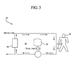
- the present system includes a fluid circuit 30 in fluid communication with a catheter 32 insertable within a patient 34 undergoing peritoneal dialysis.
- a single closed fluid path 36 is thereby defined.
- a source of dialysate is provided in a container 38 coupled to the fluid circuit 30. From the container, the dialysate can be pumped into and circulated along the fluid circuit to remove metabolic waste and/or ultrafiltrate from the patient as it passes into, through and out of the patient.
- a cleaning device 40 is coupled to the fluid circuit to clean the dialysate as it circulates along the fluid circuit 30 as previously discussed.
- At the beginning of therapy at least a portion of the dialysate is pumped into the fluid circuit 30 to fill the peritoneal cavity of the patient.
- the remaining portion, if any, of the dialysate can be pumped into the fluid circuit at a later stage in the therapy.
- a portion of the therapy fluid that has circulated along the fluid circuit can be pumped into the container 38 as the volume in therapy fluid increases due to, for example, the addition of ultrafiltrate to the fluid circuit that has been removed from the patient and/or additional amount of osmotic agent solution (not shown) added to the fluid circuit 30 as previously discussed.
- At least a portion of the container 38 can be filled with the therapy fluid in a continuous manner or intermittently.
- any suitable volume of therapy fluid can be pumped into or out of the container to compensate for a change in volume of therapy fluid during therapy.
- the fluid flow into or out of the container 38 and in circulation along the fluid circuit can be controlled at any suitable flow rates and by any suitable type and number of pumps.
- the pumps can be coupled to the system via a cycler or one or more of the pumps can be separately coupled to the system.
- the flow of fluid into or out of the container can be controlled at a flow rate of about 75 ml/min while the flow of fluid circulating along the fluid circuit can be controlled at.' about 250 ml/min as shown in Fig. 3 .
- the systems of the present invention can utilize any suitable number and type of components to facilitate effective treatment of the patient by enhancing quality of life, economic, treatment efficiency and other like treatment conditions.
- the present system can employ the use of any number and acceptable type of pumps adapted in any suitable manner such that therapy solutions, including dialysate, can be effectively fed into, circulated within and drained from the single closed fluid loop connected to the patient.
- the dialysis system of the present invention is a closed, sterile system in order to prevent air, moisture and other environmental contaminants from entering into the closed fluid loop.
- the present system can include a variety of different components to monitor for levels of contaminants in the system.
- the present system can include a gas sensor to monitor for atmospheric gases including oxygen and carbon dioxide. If detected, the present system can include any suitable device to remove the gas from the system of the present invention such that the gas can be vented to the atmosphere.
- temperature sensors are provided at desired locations along the closed fluid loop.
- the temperature sensors monitor various fluid temperatures which can be utilized to control the fluid temperatures associated with the heater.
- the system in an embodiment includes separate temperature sensors for each heater so that each heater can be controlled individually.
- the present system in an embodiment also includes various other sensors to monitor various other parameters.
- fluid pressure sensors can be electrically coupled to or otherwise communicate with a controller to provide a signal that indicates the respective fluid pressure at certain locations along the closed fluid path. Based on the signals from the pressure sensors, the controller can operate the fluid pumps and valves to obtain and maintain desired fluid pressured and flow rates in the loop running to, through and from the patient.
- the pressure sensors are non-invasive pressure sensors. These pressure sensors do not physically contact (and possibly contaminate) the medical fluid or dialysate.
- other fluid flow measurement devices such as flow rate sensors, pressure gauges, flowmeters, pressure regulators, orifice plates, mass flow meters, capacitative fluid sensor, or other flow measuring devices known to those of skill in the art may be provided in any suitable quantity and adapted to the fluid circuit.
- a flow measurement or volume sensing device which includes a capacitance sensor that measures the volume of fluid pumped trough a chamber, such as a pump chamber (not shown).
- the capacitance between the plates changes proportionally according to the function 1 / (R x V), wherein R is a known resistance and V is the voltage measured across the capacitor plates.
- the sensor operates in cooperation with a cycler pump chamber.
- the cycler pump chamber in an embodiment includes shells or walls defining a fixed and known volume and a pair of flexible membranes operating between the shells, which expand to fill with fluid and contract to discharge fluid.
- the capacitance sensor includes capacitor plates disposed on opposite sides of the pump chamber. As the volume of fluid in the chamber or fluid pump changes (i.e., the pump chamber fill or empties), the dielectric property of the varying fluids between the capacitance plates changes. For example, the combined dielectric constant of dialysate and air changes as dialysate replaces air (or air replaces dialysate) within the constant volume shells of the chamber.
- This change in the overall dielectric constant affects a change in the capacitance between the two plates, which causes a change in voltage across the capacitance plates, wherein a corresponding change in voltage can be sensed by a voltage sensing device.
- the controller monitors the change in voltage by the voltage sensing device and correlates (after a calibration of the sensor) the capacitance change to an amount of fluid pumped through chamber.
- the volume of the chamber or the pump chamber can vary, e.g., by movement of one or both the shells of the chamber.
- the capacitance between the capacitor plates changes due to a changing distance d between the plates and/or a changing surface area S of one or more of the plates, wherein the dielectric constant k is static because only one fluid resides at all times between the capacitor plates.
- the capacitance C between the capacitor plates changes based on any combination of all three of a change in dielectric constant k, distance d and surface area S.
- the controller collects a multitude of voltage signals from capacitance changes due to a plurality of chamber fill and drain cycles, wherein the controller calculates a total volume of medical fluid pumped over a length of time or numbed of pump cycles.
- the capacitance sensor monitors the medical fluid, e.g., dialysate, flow into or from the pump chamber on a real time basis, and in a non-invasive manner.
- the capacitance sensor enables the dialysis system to maintain the volume of fluid that is provided to the patient at desirable amounts and flow rates. Maintaining the fluid flow to the patient within desired levels is particularly advantageous for peritoneal dialysis therapies.
- Physiologic control such as sensing and/or adjusting parameters or the fluids, can take place at various locations in the dialysis system.
- the system can include any combination of a number of different types of physiologic level sensors.
- the system can include one or more pH sensors.
- the cartridges explained above in connection with Fig. 1 can include a pH sensor that helps to adjust the fluid so that it is maintained at a desired physiologic level.
- the present invention can include a fluid heater which can adaptedly act to heat the fluid in the closed fluid loop to a desired temperature for supplying the fluid to the patient.
- the temperature of the dialysate at initial system fill can be quite low, such as 5°C to 10°C if the fluid is stored in cold ambient temperature.
- the fluid heater is an in-line heater (continuous flow heater) that heats the fluid to the desired temperature as the fluid flows continuously past the heater.
- heaters other than in-line beaters can be used, for example, bulk heaters, a dual heater and the like.
- the fluid heater is a dual heater (not shown), including an infrared heater and a plate heater.
- a dual heater is disclosed in US-7,153,285 .
- Both the infrared heater and the plate heater are in-line heaters that heat the medical fluid that flows continuously past the heaters.
- the radiant energy or infrared heater emits infrared energy that is directed to and absorbed the fluid in the patient loop, thereby heating the fluid.
- the radiant energy or infrared heater is a primary or high capacity heater which can heat a relatively large volume of cold fluid to a desired temperature in a short period of time.
- the plate heater is a secondary or maintenance heater which has a relatively lower heating capacity relative to the infrared heater.
- the plate heater uses electrical resistance to increase the temperature of a plate that in turn heats the fluid flowing near the plate.
- the heater which includes both high and low capacity heaters, provides an efficient heater design that accommodates various fluid heading requirements.
- the radiant or infrared heater is particularly useful for quickly heating cool dialysate (high heat energy demand) that is supplied to the dialysis system, such as at the initial system fill or if there is severe heat loss during dialysis treatment.
- the temperature of the dialysate at initial system fill can be quite low, such as 5°C to 10°C if the fluid is stored in cold ambient temperature.
- the plate heater is particularly useful to maintain a desired temperature (lower heat energy demand) of the fluid being supplied to the patient, e.g., due to a normal amount of heat loss during dialysis treatment.
- the infrared heater provides for the high heat demand in a small amount of fluid exposure space, while the plate heater provides for maintenance heat demand and requires a lesser amount of input energy compared to the infrared or radiant heater. Furthermore, the heating capacity of the heater is increased if both the infrared and plate heaters are used together to heat the fluid.
- the infrared heater and the plate heater can be arranged in various configurations relative to each other.
- the heaters in an embodiment are arranged so that the fluid passes by the heaters sequentially (e.g., first the radiant or infrared heater and then the plate heater or vice versa). In another embodiment, the fluid passes by the heaters simultaneously (both heaters at the same time).
- the fluid flow path past the heaters can be a common flow path for both heaters or include independent flow paths for each heater.
- radiant or infrared electrical resistance heating other types of heating such as convective, microwave, infrared (“IR”) or inductive heating may be used.
- the heater can include a number of different components.
- the heater can include a filter made from any suitable material in any suitable filter size.
- the filter can be made of any suitable material and include any suitable filter size.
- the filter is about 0.3 microns in size, preferably about 0.22 microns. This means that the filter can remove solutes in solutions that are about 0.3 microns in size or larger with a filter size of about 0.3 microns or about 0.22 microns in size or lager for a filter size of about 0.22 microns.
- the filter can act in a variety of different ways to enhance the performance of the dialysis system of the present invention.
- the filter can be used in place of typical UV decontamination techniques or the like to disinfect the therapy fluid prior to passing into, through and out of the patient. This can effectively eliminate, or at least greatly reduce, infection in the patient as a result of the treatment, such as peritonitis which can be contracted through touch contamination during therapy.
- the filter(s) can be coupled to the fluid circuit at any suitable position.
- the filter can act to disinfect the dialysate prior to passing into the patient as previously discussed.
- the filter(s) can also be coupled to the discharge pathway. In this location, the filter can be used to remove nutrients from the therapy fluid prior to discharge. The filter can then be cleaned by, for example, back flushing with a suitable solution, to remove the filtered nutrients for reuse and reintroduction into the patient.
- the filter can be constructed in any suitable way to enhance its filtering efficiency.
- the fluid path, fluid circuit, fluid loop and/or the like of the present system can be made of one or more fluid lines interconnected in any suitable manner.
- the fluid lines can include any suitable material including a flexible, sterile and inert plastic, such as polyethylene, polystyrene, polypropylene, polyvinyl chloride and/or combinations thereof.
- the fluid lines are transparent such that the fluid flow through the lines can be visually observed.
Landscapes
- Health & Medical Sciences (AREA)
- Urology & Nephrology (AREA)
- Heart & Thoracic Surgery (AREA)
- Emergency Medicine (AREA)
- Anesthesiology (AREA)
- Engineering & Computer Science (AREA)
- Vascular Medicine (AREA)
- Biomedical Technology (AREA)
- Hematology (AREA)
- Life Sciences & Earth Sciences (AREA)
- Animal Behavior & Ethology (AREA)
- General Health & Medical Sciences (AREA)
- Public Health (AREA)
- Veterinary Medicine (AREA)
- External Artificial Organs (AREA)
Priority Applications (2)
| Application Number | Priority Date | Filing Date | Title |
|---|---|---|---|
| EP09075523A EP2168612A3 (en) | 2002-07-19 | 2003-07-16 | Systems and methods for peritoneal dialysis |
| EP10075478A EP2298377A1 (en) | 2002-07-19 | 2003-07-16 | Systems and methods for peritoneal dialysis |
Applications Claiming Priority (3)
| Application Number | Priority Date | Filing Date | Title |
|---|---|---|---|
| US39704502P | 2002-07-19 | 2002-07-19 | |
| US397045P | 2002-07-19 | ||
| PCT/US2003/022269 WO2004009156A2 (en) | 2002-07-19 | 2003-07-16 | Systems and methods for peritoneal dialysis |
Related Child Applications (1)
| Application Number | Title | Priority Date | Filing Date |
|---|---|---|---|
| EP09075523A Division EP2168612A3 (en) | 2002-07-19 | 2003-07-16 | Systems and methods for peritoneal dialysis |
Publications (2)
| Publication Number | Publication Date |
|---|---|
| EP1523351A2 EP1523351A2 (en) | 2005-04-20 |
| EP1523351B1 true EP1523351B1 (en) | 2010-01-06 |
Family
ID=30770981
Family Applications (3)
| Application Number | Title | Priority Date | Filing Date |
|---|---|---|---|
| EP03765631A Revoked EP1523351B1 (en) | 2002-07-19 | 2003-07-16 | System for peritoneal dialysis |
| EP10075478A Withdrawn EP2298377A1 (en) | 2002-07-19 | 2003-07-16 | Systems and methods for peritoneal dialysis |
| EP09075523A Withdrawn EP2168612A3 (en) | 2002-07-19 | 2003-07-16 | Systems and methods for peritoneal dialysis |
Family Applications After (2)
| Application Number | Title | Priority Date | Filing Date |
|---|---|---|---|
| EP10075478A Withdrawn EP2298377A1 (en) | 2002-07-19 | 2003-07-16 | Systems and methods for peritoneal dialysis |
| EP09075523A Withdrawn EP2168612A3 (en) | 2002-07-19 | 2003-07-16 | Systems and methods for peritoneal dialysis |
Country Status (10)
| Country | Link |
|---|---|
| US (5) | US7208092B2 (OSRAM) |
| EP (3) | EP1523351B1 (OSRAM) |
| JP (3) | JP4460448B2 (OSRAM) |
| AT (1) | ATE454176T1 (OSRAM) |
| AU (1) | AU2003249297A1 (OSRAM) |
| DE (1) | DE60330868D1 (OSRAM) |
| DK (1) | DK1523351T3 (OSRAM) |
| ES (1) | ES2339239T3 (OSRAM) |
| MX (1) | MXPA05000818A (OSRAM) |
| WO (1) | WO2004009156A2 (OSRAM) |
Families Citing this family (163)
| Publication number | Priority date | Publication date | Assignee | Title |
|---|---|---|---|---|
| US6503062B1 (en) * | 2000-07-10 | 2003-01-07 | Deka Products Limited Partnership | Method for regulating fluid pump pressure |
| US7241272B2 (en) | 2001-11-13 | 2007-07-10 | Baxter International Inc. | Method and composition for removing uremic toxins in dialysis processes |
| DE10224750A1 (de) | 2002-06-04 | 2003-12-24 | Fresenius Medical Care De Gmbh | Vorrichtung zur Behandlung einer medizinischen Flüssigkeit |
| JP4890761B2 (ja) | 2002-07-19 | 2012-03-07 | バクスター・インターナショナル・インコーポレイテッド | 腹膜透析を実施するためのシステムおよび方法 |
| EP1523351B1 (en) * | 2002-07-19 | 2010-01-06 | Baxter International Inc. | System for peritoneal dialysis |
| US7238164B2 (en) | 2002-07-19 | 2007-07-03 | Baxter International Inc. | Systems, methods and apparatuses for pumping cassette-based therapies |
| ATE510605T1 (de) * | 2003-03-14 | 2011-06-15 | Univ Columbia | Systeme und verfahren für auf blut basierende therapien mit einer membranlosen mikrofluid- austauschvorrichtung |
| US20060076295A1 (en) * | 2004-03-15 | 2006-04-13 | The Trustees Of Columbia University In The City Of New York | Systems and methods of blood-based therapies having a microfluidic membraneless exchange device |
| US8803044B2 (en) * | 2003-11-05 | 2014-08-12 | Baxter International Inc. | Dialysis fluid heating systems |
| US7776006B2 (en) * | 2003-11-05 | 2010-08-17 | Baxter International Inc. | Medical fluid pumping system having real time volume determination |
| US8029454B2 (en) | 2003-11-05 | 2011-10-04 | Baxter International Inc. | High convection home hemodialysis/hemofiltration and sorbent system |
| US8038639B2 (en) | 2004-11-04 | 2011-10-18 | Baxter International Inc. | Medical fluid system with flexible sheeting disposable unit |
| WO2006086490A1 (en) | 2005-02-07 | 2006-08-17 | Medtronic, Inc. | Ion imbalance detector |
| US7935074B2 (en) * | 2005-02-28 | 2011-05-03 | Fresenius Medical Care Holdings, Inc. | Cassette system for peritoneal dialysis machine |
| US20060195064A1 (en) * | 2005-02-28 | 2006-08-31 | Fresenius Medical Care Holdings, Inc. | Portable apparatus for peritoneal dialysis therapy |
| US8197231B2 (en) | 2005-07-13 | 2012-06-12 | Purity Solutions Llc | Diaphragm pump and related methods |
| RU2426561C2 (ru) * | 2006-01-30 | 2011-08-20 | Дзе Риджентс Оф Дзе Юниверсити Оф Калифорния | Способы и устройство для перитонеального диализа |
| US8012118B2 (en) * | 2006-03-08 | 2011-09-06 | Fresenius Medical Care Holdings, Inc. | Artificial kidney dialysis system |
| US8715221B2 (en) * | 2006-03-08 | 2014-05-06 | Fresenius Medical Care Holdings, Inc. | Wearable kidney |
| WO2007118235A2 (en) * | 2006-04-07 | 2007-10-18 | Nxstage Medical Inc. | Filtration system for preparation of fluids for medical applications. |
| US7727399B2 (en) * | 2006-05-22 | 2010-06-01 | The Trustees Of Columbia University In The City Of New York | Systems and methods of microfluidic membraneless exchange using filtration of extraction outlet streams |
| US8226595B2 (en) | 2006-05-26 | 2012-07-24 | Baxter International Inc. | Automated dialysis system driven by gravity and vacuum |
| EP2041116A1 (de) * | 2006-07-07 | 2009-04-01 | Boehringer Ingelheim International GmbH | Phenyl substituierte heteroaryl-derivate und deren verwendung als antitumormittel |
| US8870811B2 (en) * | 2006-08-31 | 2014-10-28 | Fresenius Medical Care Holdings, Inc. | Peritoneal dialysis systems and related methods |
| US8926550B2 (en) * | 2006-08-31 | 2015-01-06 | Fresenius Medical Care Holdings, Inc. | Data communication system for peritoneal dialysis machine |
| US8606626B1 (en) | 2007-01-31 | 2013-12-10 | Experian Information Solutions, Inc. | Systems and methods for providing a direct marketing campaign planning environment |
| CA2687682C (en) * | 2007-05-29 | 2017-10-31 | Fresenius Medical Care Holdings, Inc. | Solutions, dialysates, and related methods |
| US8512553B2 (en) | 2007-07-05 | 2013-08-20 | Baxter International Inc. | Extracorporeal dialysis ready peritoneal dialysis machine |
| US8764702B2 (en) * | 2007-07-05 | 2014-07-01 | Baxter International Inc. | Dialysis system having dual patient line connection and prime |
| US7736328B2 (en) | 2007-07-05 | 2010-06-15 | Baxter International Inc. | Dialysis system having supply container autoconnection |
| US7909795B2 (en) * | 2007-07-05 | 2011-03-22 | Baxter International Inc. | Dialysis system having disposable cassette and interface therefore |
| US8078333B2 (en) * | 2007-07-05 | 2011-12-13 | Baxter International Inc. | Dialysis fluid heating algorithms |
| US8715235B2 (en) * | 2007-07-05 | 2014-05-06 | Baxter International Inc. | Dialysis system having disposable cassette and heated cassette interface |
| US7892197B2 (en) * | 2007-09-19 | 2011-02-22 | Fresenius Medical Care Holdings, Inc. | Automatic prime of an extracorporeal blood circuit |
| US9415150B2 (en) | 2007-11-09 | 2016-08-16 | Baxter Healthcare S.A. | Balanced flow dialysis machine |
| US8449500B2 (en) * | 2007-11-16 | 2013-05-28 | Baxter International Inc. | Flow pulsatility dampening devices for closed-loop controlled infusion systems |
| US9101716B2 (en) | 2008-02-01 | 2015-08-11 | Baxter International Inc. | Multi-pass dialysis |
| CA2714594A1 (en) * | 2008-02-04 | 2009-08-13 | Edward F. Leonard | Fluid separation devices, systems and methods |
| US7892423B2 (en) * | 2008-02-14 | 2011-02-22 | Baxter International Inc. | Dialysis system including multi-heater power coordination |
| US10973968B2 (en) | 2008-02-14 | 2021-04-13 | Baxter International Inc. | Control of a water device via a dialysis machine user interface |
| US9348975B2 (en) * | 2008-05-02 | 2016-05-24 | Baxter International Inc. | Optimizing therapy outcomes for peritoneal dialysis |
| US8882700B2 (en) * | 2008-05-02 | 2014-11-11 | Baxter International Inc. | Smart patient transfer set for peritoneal dialysis |
| AU2009263046B2 (en) * | 2008-06-23 | 2014-07-24 | Temasek Polytechnic | A flow system of a dialysis device and a portable dialysis device |
| US9821105B2 (en) | 2008-07-01 | 2017-11-21 | Baxter International Inc. | Nanoclay sorbents for dialysis |
| US8168063B2 (en) | 2008-07-09 | 2012-05-01 | Baxter International Inc. | Dialysis system having filtering method for determining therapy prescriptions |
| US7981281B2 (en) * | 2008-07-09 | 2011-07-19 | Baxter International, Inc. | Dialysis system having regimen generation methodology |
| US9514283B2 (en) | 2008-07-09 | 2016-12-06 | Baxter International Inc. | Dialysis system having inventory management including online dextrose mixing |
| US8057679B2 (en) | 2008-07-09 | 2011-11-15 | Baxter International Inc. | Dialysis system having trending and alert generation |
| US8062513B2 (en) | 2008-07-09 | 2011-11-22 | Baxter International Inc. | Dialysis system and machine having therapy prescription recall |
| US10265454B2 (en) | 2008-07-25 | 2019-04-23 | Baxter International Inc. | Dialysis system with flow regulation device |
| US20100051552A1 (en) | 2008-08-28 | 2010-03-04 | Baxter International Inc. | In-line sensors for dialysis applications |
| CA2737071C (en) | 2008-10-03 | 2016-08-02 | Fresenius Medical Care Holdings, Inc. | Zirconium phosphate particles having improved adsorption capacity and method of synthesizing the same |
| CN102202702B (zh) * | 2008-11-03 | 2014-05-21 | 弗雷泽纽斯医疗保健控股有限公司 | 便携式腹膜透析系统 |
| US8192401B2 (en) | 2009-03-20 | 2012-06-05 | Fresenius Medical Care Holdings, Inc. | Medical fluid pump systems and related components and methods |
| US8282829B2 (en) | 2009-05-20 | 2012-10-09 | Baxter International Inc. | System and method for automated data collection of twenty-four hour ultrafiltration and other patient parameters using wired or wireless technology |
| US8926551B2 (en) * | 2009-07-07 | 2015-01-06 | Baxter Healthcare Inc. | Peritoneal dialysis therapy with large dialysis solution volumes |
| EP2453946B1 (en) | 2009-07-15 | 2013-02-13 | Fresenius Medical Care Holdings, Inc. | Medical fluid cassettes and related systems |
| ITBO20090471A1 (it) * | 2009-07-22 | 2011-01-23 | Bellco S R L Con Unico Socio | Rene artificiale indossabile con sistema rigenerativo |
| ITBO20090473A1 (it) * | 2009-07-22 | 2011-01-23 | Bellco S R L Con Unico Socio | Macchina da dialisi con sistema rigenerativo |
| US8720913B2 (en) * | 2009-08-11 | 2014-05-13 | Fresenius Medical Care Holdings, Inc. | Portable peritoneal dialysis carts and related systems |
| US8556889B2 (en) * | 2009-09-29 | 2013-10-15 | Covidien Lp | Flow rate monitor for fluid cooled microwave ablation probe |
| US9399091B2 (en) | 2009-09-30 | 2016-07-26 | Medtronic, Inc. | System and method to regulate ultrafiltration |
| US8366667B2 (en) | 2010-02-11 | 2013-02-05 | Baxter International Inc. | Flow pulsatility dampening devices |
| US8936720B2 (en) | 2010-09-17 | 2015-01-20 | Baxter International Inc. | Drain and fill logic for automated peritoneal dialysis |
| DE102010053973A1 (de) | 2010-12-09 | 2012-06-14 | Fresenius Medical Care Deutschland Gmbh | Medizinisches Gerät mit einer Heizung |
| US9694125B2 (en) | 2010-12-20 | 2017-07-04 | Fresenius Medical Care Holdings, Inc. | Medical fluid cassettes and related systems and methods |
| US9624915B2 (en) | 2011-03-09 | 2017-04-18 | Fresenius Medical Care Holdings, Inc. | Medical fluid delivery sets and related systems and methods |
| US9861733B2 (en) | 2012-03-23 | 2018-01-09 | Nxstage Medical Inc. | Peritoneal dialysis systems, devices, and methods |
| EP3536361B1 (en) | 2011-03-23 | 2020-10-07 | NxStage Medical Inc. | Peritoneal dialysis systems, devices, and methods |
| EP2699280B1 (en) | 2011-04-21 | 2015-12-09 | Fresenius Medical Care Holdings, Inc. | Medical fluid pumping systems and related devices and methods |
| US9456755B2 (en) | 2011-04-29 | 2016-10-04 | Medtronic, Inc. | Method and device to monitor patients with kidney disease |
| US9561316B2 (en) | 2011-04-29 | 2017-02-07 | Medtronic, Inc. | Intersession monitoring for blood fluid removal therapy |
| US9848778B2 (en) | 2011-04-29 | 2017-12-26 | Medtronic, Inc. | Method and device to monitor patients with kidney disease |
| CN103889481B (zh) | 2011-08-02 | 2016-03-09 | 美敦力公司 | 带有具有可控的顺应性容积的流动路径的血液透析系统 |
| US10857277B2 (en) | 2011-08-16 | 2020-12-08 | Medtronic, Inc. | Modular hemodialysis system |
| CN103842004B (zh) | 2011-08-22 | 2016-11-23 | 美敦力公司 | 双流吸附剂盒 |
| US9186449B2 (en) | 2011-11-01 | 2015-11-17 | Fresenius Medical Care Holdings, Inc. | Dialysis machine support assemblies and related systems and methods |
| US20130146541A1 (en) | 2011-12-13 | 2013-06-13 | Nxstage Medical, Inc. | Fluid purification methods, devices, and systems |
| US9713668B2 (en) | 2012-01-04 | 2017-07-25 | Medtronic, Inc. | Multi-staged filtration system for blood fluid removal |
| US9610392B2 (en) | 2012-06-08 | 2017-04-04 | Fresenius Medical Care Holdings, Inc. | Medical fluid cassettes and related systems and methods |
| US9500188B2 (en) | 2012-06-11 | 2016-11-22 | Fresenius Medical Care Holdings, Inc. | Medical fluid cassettes and related systems and methods |
| US10905816B2 (en) | 2012-12-10 | 2021-02-02 | Medtronic, Inc. | Sodium management system for hemodialysis |
| US9713666B2 (en) | 2013-01-09 | 2017-07-25 | Medtronic, Inc. | Recirculating dialysate fluid circuit for blood measurement |
| US9707328B2 (en) | 2013-01-09 | 2017-07-18 | Medtronic, Inc. | Sorbent cartridge to measure solute concentrations |
| US11565029B2 (en) | 2013-01-09 | 2023-01-31 | Medtronic, Inc. | Sorbent cartridge with electrodes |
| US11154648B2 (en) | 2013-01-09 | 2021-10-26 | Medtronic, Inc. | Fluid circuits for sorbent cartridge with sensors |
| US10543052B2 (en) | 2013-02-01 | 2020-01-28 | Medtronic, Inc. | Portable dialysis cabinet |
| US10010663B2 (en) | 2013-02-01 | 2018-07-03 | Medtronic, Inc. | Fluid circuit for delivery of renal replacement therapies |
| US9623164B2 (en) | 2013-02-01 | 2017-04-18 | Medtronic, Inc. | Systems and methods for multifunctional volumetric fluid control |
| US9526822B2 (en) | 2013-02-01 | 2016-12-27 | Medtronic, Inc. | Sodium and buffer source cartridges for use in a modular controlled compliant flow path |
| US10850016B2 (en) | 2013-02-01 | 2020-12-01 | Medtronic, Inc. | Modular fluid therapy system having jumpered flow paths and systems and methods for cleaning and disinfection |
| US9827361B2 (en) | 2013-02-02 | 2017-11-28 | Medtronic, Inc. | pH buffer measurement system for hemodialysis systems |
| US9144640B2 (en) | 2013-02-02 | 2015-09-29 | Medtronic, Inc. | Sorbent cartridge configurations for improved dialysate regeneration |
| US9561323B2 (en) | 2013-03-14 | 2017-02-07 | Fresenius Medical Care Holdings, Inc. | Medical fluid cassette leak detection methods and devices |
| US9433720B2 (en) | 2013-03-14 | 2016-09-06 | Fresenius Medical Care Holdings, Inc. | Universal portable artificial kidney for hemodialysis and peritoneal dialysis |
| JP6334673B2 (ja) | 2013-03-14 | 2018-05-30 | バクスター・インターナショナル・インコーポレイテッドBaxter International Incorp0Rated | 再使用可能な作動ユニットを有する腹膜透析交換のためのシステム及び方法 |
| US9440017B2 (en) | 2013-03-14 | 2016-09-13 | Baxter International Inc. | System and method for performing alternative and sequential blood and peritoneal dialysis modalities |
| US20140263062A1 (en) | 2013-03-14 | 2014-09-18 | Fresenius Medical Care Holdings, Inc. | Universal portable machine for online hemodiafiltration using regenerated dialysate |
| US9566377B2 (en) | 2013-03-15 | 2017-02-14 | Fresenius Medical Care Holdings, Inc. | Medical fluid sensing and concentration determination in a fluid cartridge with multiple passageways, using a radio frequency device situated within a magnetic field |
| US9597439B2 (en) | 2013-03-15 | 2017-03-21 | Fresenius Medical Care Holdings, Inc. | Medical fluid sensing and concentration determination using radio frequency energy and a magnetic field |
| US9713664B2 (en) | 2013-03-15 | 2017-07-25 | Fresenius Medical Care Holdings, Inc. | Nuclear magnetic resonance module for a dialysis machine |
| US9433718B2 (en) | 2013-03-15 | 2016-09-06 | Fresenius Medical Care Holdings, Inc. | Medical fluid system including radio frequency (RF) device within a magnetic assembly, and fluid cartridge body with one of multiple passageways disposed within the RF device, and specially configured cartridge gap accepting a portion of said RF device |
| US9772386B2 (en) | 2013-03-15 | 2017-09-26 | Fresenius Medical Care Holdings, Inc. | Dialysis system with sample concentration determination device using magnet and radio frequency coil assemblies |
| US10117985B2 (en) | 2013-08-21 | 2018-11-06 | Fresenius Medical Care Holdings, Inc. | Determining a volume of medical fluid pumped into or out of a medical fluid cassette |
| EP3102107A4 (en) | 2013-11-04 | 2018-02-07 | Medtronic, Inc. | Method and device to manage fluid volumes in the body |
| US10052612B2 (en) | 2013-11-26 | 2018-08-21 | Medtronic, Inc. | Zirconium phosphate recharging method and apparatus |
| US9895477B2 (en) | 2013-11-26 | 2018-02-20 | Medtronic, Inc. | Detachable module for recharging sorbent materials with optional bypass |
| US9943780B2 (en) | 2013-11-26 | 2018-04-17 | Medtronic, Inc. | Module for in-line recharging of sorbent materials with optional bypass |
| US9884145B2 (en) | 2013-11-26 | 2018-02-06 | Medtronic, Inc. | Parallel modules for in-line recharging of sorbents using alternate duty cycles |
| US10004839B2 (en) | 2013-11-26 | 2018-06-26 | Medtronic, Inc. | Multi-use sorbent cartridge |
| US10537875B2 (en) | 2013-11-26 | 2020-01-21 | Medtronic, Inc. | Precision recharging of sorbent materials using patient and session data |
| ES3040293T3 (en) | 2013-11-27 | 2025-10-29 | Mozarc Medical Us Llc | Precision dialysis monitoring and synchonization system |
| DE102014104396A1 (de) * | 2014-03-28 | 2015-10-01 | Olympus Winter & Ibe Gmbh | Vorrichtung zum Erwärmen von dem menschlichen Körper zuzuführenden Flüssigkeiten |
| US10286135B2 (en) | 2014-03-28 | 2019-05-14 | Fresenius Medical Care Holdings, Inc. | Measuring conductivity of a medical fluid |
| WO2015199764A1 (en) | 2014-06-24 | 2015-12-30 | Medtronic, Inc. | Replenishing urease in dialysis systems using urease pouches |
| US10016553B2 (en) | 2014-06-24 | 2018-07-10 | Medtronic, Inc. | Replenishing urease in dialysis systems using a urease introducer |
| WO2015199761A1 (en) | 2014-06-24 | 2015-12-30 | Medtronic, Inc. | Sorbent pouch |
| US10357757B2 (en) | 2014-06-24 | 2019-07-23 | Medtronic, Inc. | Stacked sorbent assembly |
| CN106604752B (zh) | 2014-06-24 | 2019-07-09 | 美敦力公司 | 用于补充吸附剂盒内的脲酶的脲酶引入系统 |
| US10172991B2 (en) | 2014-06-24 | 2019-01-08 | Medtronic, Inc. | Modular dialysate regeneration assembly |
| US20170304527A1 (en) * | 2014-10-03 | 2017-10-26 | Mayo Foundation For Medical Education And Research | Wound irrigation system |
| US10874787B2 (en) | 2014-12-10 | 2020-12-29 | Medtronic, Inc. | Degassing system for dialysis |
| US9713665B2 (en) | 2014-12-10 | 2017-07-25 | Medtronic, Inc. | Degassing system for dialysis |
| US9895479B2 (en) | 2014-12-10 | 2018-02-20 | Medtronic, Inc. | Water management system for use in dialysis |
| US10098993B2 (en) | 2014-12-10 | 2018-10-16 | Medtronic, Inc. | Sensing and storage system for fluid balance |
| JP2018524718A (ja) | 2015-06-25 | 2018-08-30 | ガンブロ・ルンディア・エービーGambro Lundia Ab | 分散データベースを有する医療装置システム及び方法 |
| US10335534B2 (en) | 2015-11-06 | 2019-07-02 | Medtronic, Inc. | Dialysis prescription optimization for decreased arrhythmias |
| US10994064B2 (en) | 2016-08-10 | 2021-05-04 | Medtronic, Inc. | Peritoneal dialysate flow path sensing |
| US10874790B2 (en) | 2016-08-10 | 2020-12-29 | Medtronic, Inc. | Peritoneal dialysis intracycle osmotic agent adjustment |
| US12329892B2 (en) | 2016-04-04 | 2025-06-17 | Mozarc Medical Us Llc | Dextrose concentration sensor for a peritoneal dialysis system |
| US10828412B2 (en) | 2016-05-06 | 2020-11-10 | Gambro Lundia Ab | Systems and methods for peritoneal dialysis having point of use dialysis fluid preparation including mixing and heating therefore |
| US11534537B2 (en) | 2016-08-19 | 2022-12-27 | Outset Medical, Inc. | Peritoneal dialysis system and methods |
| US11013843B2 (en) | 2016-09-09 | 2021-05-25 | Medtronic, Inc. | Peritoneal dialysis fluid testing system |
| US20180104401A1 (en) * | 2016-10-19 | 2018-04-19 | Government Of The United States As Represented By The Secretary Of The Air Force | Method for peritoneal removal of electrolytes and inflammatory mediators |
| DE102016013875A1 (de) | 2016-11-19 | 2018-05-24 | Fresenius Medical Care Deutschland Gmbh | Dialysemaschine und Reinigungsverfahren für die Dialysemaschine |
| US10981148B2 (en) | 2016-11-29 | 2021-04-20 | Medtronic, Inc. | Zirconium oxide module conditioning |
| CA3044724A1 (en) | 2016-12-21 | 2018-06-28 | Gambro Lundia Ab | Medical device system including information technology infrastructure having secure cluster domain supporting external domain |
| US11167070B2 (en) | 2017-01-30 | 2021-11-09 | Medtronic, Inc. | Ganged modular recharging system |
| KR101880585B1 (ko) * | 2017-03-22 | 2018-07-23 | 서울대학교산학협력단 | 복막투석액 삼투압조절장치 |
| US11135345B2 (en) | 2017-05-10 | 2021-10-05 | Fresenius Medical Care Holdings, Inc. | On demand dialysate mixing using concentrates |
| US10960381B2 (en) | 2017-06-15 | 2021-03-30 | Medtronic, Inc. | Zirconium phosphate disinfection recharging and conditioning |
| US11179516B2 (en) | 2017-06-22 | 2021-11-23 | Baxter International Inc. | Systems and methods for incorporating patient pressure into medical fluid delivery |
| WO2018237375A1 (en) | 2017-06-24 | 2018-12-27 | Nxstage Medical, Inc. | Peritoneal dialysis fluid preparation and/or treatment devices methods and systems |
| US11278654B2 (en) | 2017-12-07 | 2022-03-22 | Medtronic, Inc. | Pneumatic manifold for a dialysis system |
| US11033667B2 (en) | 2018-02-02 | 2021-06-15 | Medtronic, Inc. | Sorbent manifold for a dialysis system |
| US11110215B2 (en) | 2018-02-23 | 2021-09-07 | Medtronic, Inc. | Degasser and vent manifolds for dialysis |
| JP2021516089A (ja) * | 2018-02-28 | 2021-07-01 | ネクステージ メディカル インコーポレイテッド | 流体調製および処置装置、方法、およびシステム |
| WO2019204195A1 (en) | 2018-04-17 | 2019-10-24 | Deka Products Limited Partnership | Peritoneal dialysis cassette with pneumatic pump |
| US12285552B2 (en) | 2018-08-14 | 2025-04-29 | Mozarc Medical Us Llc | Precision dialysis therapy based on sorbent effluent analysis |
| US11213616B2 (en) | 2018-08-24 | 2022-01-04 | Medtronic, Inc. | Recharge solution for zirconium phosphate |
| US11504458B2 (en) | 2018-10-17 | 2022-11-22 | Fresenius Medical Care Holdings, Inc. | Ultrasonic authentication for dialysis |
| US11806457B2 (en) | 2018-11-16 | 2023-11-07 | Mozarc Medical Us Llc | Peritoneal dialysis adequacy meaurements |
| US11806456B2 (en) | 2018-12-10 | 2023-11-07 | Mozarc Medical Us Llc | Precision peritoneal dialysis therapy based on dialysis adequacy measurements |
| US12433976B2 (en) | 2019-01-08 | 2025-10-07 | Mozarc Medical Us Llc | Bicarbonate sensor for dialysis |
| AU2020266584B2 (en) | 2019-04-30 | 2025-10-23 | Outset Medical, Inc. | Dialysis system and methods |
| US11484636B2 (en) * | 2020-04-16 | 2022-11-01 | Fresenius Medical Care Holdings, Inc. | Medical device having integrated sterile work platform |
| US12128165B2 (en) | 2020-04-27 | 2024-10-29 | Mozarc Medical Us Llc | Dual stage degasser |
| US12397093B2 (en) | 2021-05-18 | 2025-08-26 | Mozarc Medical Us Llc | Sorbent cartridge designs |
| US12154673B2 (en) | 2021-08-02 | 2024-11-26 | Mozarc Medical Us Llc | Artificial intelligence assisted home therapy settings for dialysis |
| US11850344B2 (en) | 2021-08-11 | 2023-12-26 | Mozarc Medical Us Llc | Gas bubble sensor |
| US11965763B2 (en) | 2021-11-12 | 2024-04-23 | Mozarc Medical Us Llc | Determining fluid flow across rotary pump |
| US11944733B2 (en) | 2021-11-18 | 2024-04-02 | Mozarc Medical Us Llc | Sodium and bicarbonate control |
| CN115715829B (zh) * | 2022-11-18 | 2024-05-17 | 中国船舶集团有限公司第七一六研究所 | 便携式体外循环系统 |
Family Cites Families (199)
| Publication number | Priority date | Publication date | Assignee | Title |
|---|---|---|---|---|
| US2122509A (en) * | 1935-08-22 | 1938-07-05 | Stephen B Beliaeff | Hair waving or curling device |
| US2529028A (en) | 1947-07-31 | 1950-11-07 | Landon Standard Pools | Chemical feeder |
| US3332737A (en) * | 1965-01-28 | 1967-07-25 | Kurt A Kraus | Process for separating inorganic anions with hydrous oxide anion exchangers |
| US3388803A (en) * | 1965-04-16 | 1968-06-18 | Applied Biolog Sciences Lab In | Wearable dialysis apparatus |
| US3463728A (en) * | 1967-04-28 | 1969-08-26 | Us Health Education & Welfare | Dialysate capacity augmentation process |
| US3485245A (en) | 1967-06-21 | 1969-12-23 | Ibm | Portable fluid heater |
| GB1189458A (en) | 1967-09-27 | 1970-04-29 | Nat Res Dev | Improvements in or relating to dialysers |
| US3545438A (en) | 1968-02-12 | 1970-12-08 | Sarns Inc | Intermittent dialysis method and apparatus therefor |
| US3799873A (en) * | 1968-04-19 | 1974-03-26 | Hydronautics | Artificial kidney |
| US3825493A (en) * | 1972-09-29 | 1974-07-23 | Hydronautics | Peritoneal artificial kidney |
| US3490479A (en) * | 1968-07-12 | 1970-01-20 | Honeywell Inc | Fluid pressure relay |
| US3669878A (en) * | 1968-12-02 | 1972-06-13 | Health Education And Welfare U | Treatment of dialysate solution for removal of urea |
| FR2036413A5 (OSRAM) | 1969-03-13 | 1970-12-24 | Thomson Csf | |
| GB1280521A (en) * | 1969-06-28 | 1972-07-05 | Whitely Lang And Neill Ltd | Peritoneal dialysis apparatus |
| US3669880A (en) * | 1969-06-30 | 1972-06-13 | Cci Aerospace Corp | Recirculation dialysate system for use with an artificial kidney machine |
| US3667612A (en) * | 1969-09-04 | 1972-06-06 | Joe H Leonard | Artificial kidney system |
| BE759038A (fr) | 1969-11-17 | 1971-04-30 | Cci Aerospace Corp | Module a dialysat a remise en circulation, destine a etre jete |
| US3619423A (en) | 1970-04-20 | 1971-11-09 | Us Health Education & Welfare | Cascade dialysis apparatus and method |
| US3682817A (en) * | 1970-08-02 | 1972-08-08 | Bio Cal Instr Co | Dialyzer |
| US3707967A (en) | 1970-10-01 | 1973-01-02 | Tecna Corp | Steady flow regenerative peritoneal dialysis system and method |
| DE2239254C2 (de) | 1970-12-30 | 1983-08-04 | Organon Teknika Corp., Oklahoma City, Okla. | "Säule zur Regenerierung einer zirkulierenden Dialysatlösung und Verwendung dieser Säule". |
| US3727612A (en) * | 1971-01-18 | 1973-04-17 | R Sayers | Dialysis method and apparatus |
| US3697418A (en) | 1971-01-25 | 1972-10-10 | Cci Aerospace Corp | Method and apparatus for regenerating the dialyzing fluid for an artificial kidney |
| FR2129165A5 (OSRAM) | 1971-03-17 | 1972-10-27 | Rhone Poulenc Sa | |
| US3850835A (en) | 1971-11-08 | 1974-11-26 | Cci Life Systems Inc | Method of making granular zirconium hydrous oxide ion exchangers, such as zirconium phosphate and hydrous zirconium oxide, particularly for column use |
| BE792314A (fr) * | 1971-12-06 | 1973-06-05 | Rhone Poulenc Sa | Perfectionnement aux reins artificiels |
| FR2165006A5 (OSRAM) * | 1971-12-14 | 1973-08-03 | Rhone Poulenc Sa | |
| FR2170868B1 (OSRAM) | 1972-02-04 | 1976-07-09 | Rhone Poulenc Ind | |
| US4012317A (en) | 1972-02-04 | 1977-03-15 | Rhone-Poulenc S.A. | Process for extracting urea from a solution with alkenylaromatic polymers with α-ketoalhydic groups |
| US3878564A (en) * | 1972-04-14 | 1975-04-22 | Shang J Yao | Blood and tissue detoxification method |
| US3979284A (en) | 1972-07-31 | 1976-09-07 | Rhone-Poulenc S.A. | Artificial haemodialysis kidneys |
| US3911915A (en) | 1972-09-05 | 1975-10-14 | Einstein Coll Med | Dialytic introduction of maltose into bloodstream |
| US3809241A (en) * | 1973-02-23 | 1974-05-07 | Electro Sys Eng Inc | Self-container kidney dialysis apparatus |
| US4036747A (en) * | 1973-02-27 | 1977-07-19 | Takeda Chemical Industries, Ltd. | Adsorbent for recycling artificial kidney |
| US3884808A (en) * | 1973-06-20 | 1975-05-20 | Res Dev Systems Inc | Wearable, self-regenerating dialysis appliance |
| US4192748A (en) * | 1973-07-05 | 1980-03-11 | Hyden Viktor H | Dialysis apparatus with selective chemical activity |
| USRE32303E (en) | 1973-07-31 | 1986-12-09 | American Medical Products Corp. | Peritoneal dialysis apparatus |
| JPS5225197B2 (OSRAM) | 1973-09-19 | 1977-07-06 | ||
| US4118314A (en) | 1974-01-09 | 1978-10-03 | Seisan Kaihatsu Kagaku Kenkyusho | Apparatus for treatment of artificial kidney dialyzing fluid |
| US4031010A (en) * | 1974-05-02 | 1977-06-21 | Takeda Chemical Industries, Ltd. | Combined dialyzer and adsorber unit |
| IT1014620B (it) | 1974-05-06 | 1977-04-30 | Bellco Spa | Procedimento per la rigenerazione di liquidi dializzanti in sistemi di emodialisi |
| US4081372A (en) * | 1975-12-08 | 1978-03-28 | University Of Utah | Leakage indicator for recirculating peritoneal dialysis system |
| IL49031A (en) * | 1976-02-13 | 1979-11-30 | Ramot Plastics | Peritoneal artificial kidney |
| DE2705734C3 (de) * | 1977-02-11 | 1982-04-22 | Akzo Gmbh, 5600 Wuppertal | Dialysemembran für die Hämodialyse |
| SE402212B (sv) * | 1976-10-14 | 1978-06-26 | Gambro Ab | Dialyssystem |
| JPS5532384Y2 (OSRAM) | 1976-10-20 | 1980-08-01 | ||
| US4194536A (en) * | 1976-12-09 | 1980-03-25 | Eaton Corporation | Composite tubing product |
| FR2385406A1 (fr) * | 1977-03-28 | 1978-10-27 | Akzo Nv | Rein artificiel |
| NL7703937A (nl) | 1977-04-12 | 1978-10-16 | Organon Teknika Bv | Inrichting voorzien van een sorbent voor het zuiveren van bloed; een voor orale toepassing geschikt sorbent en een werkwijze voor vervaar- diging van het sorbent. |
| US4173537A (en) | 1977-05-23 | 1979-11-06 | Newhart Earle E | Integral artificial kidney unit |
| US4190047A (en) * | 1977-08-26 | 1980-02-26 | University Of Utah | Method and apparatus for peritoneal dialysis |
| US4364747A (en) | 1977-08-29 | 1982-12-21 | The Regents Of The University Of Minnesota | System for regenerative thermally reversed adsorption |
| DE2755214C3 (de) | 1977-12-10 | 1980-12-11 | Dr. Eduard Fresenius Chemisch-Pharmazeutische Industrie Kg Apparatebau Kg, 6380 Bad Homburg | Vorrichtung zur periodischen Spülung der Bauchhöhle |
| IT1092077B (it) | 1978-01-20 | 1985-07-06 | Bellco Spa | Macchina portatile per dialisi a rigenerazione |
| JPS54109291A (en) | 1978-02-16 | 1979-08-27 | Genshirou Ogawa | Heater structure for instillation liquid* transfusion blood or like |
| US4581141A (en) * | 1978-02-27 | 1986-04-08 | Purdue Research Foundation | Dialysis material and method for removing uremic substances |
| US4256718A (en) * | 1978-03-20 | 1981-03-17 | Organon Teknika Corporation | Sodium zirconium carbonate compound and the method of its preparation |
| IT1174707B (it) * | 1978-05-03 | 1987-07-01 | Bonomini Vittorio | Rene artificiale portatile per dialisi |
| SE428427B (sv) * | 1979-01-04 | 1983-07-04 | Gambro Lundia Ab | Sett att bortskaffa avfallsmetaboliter speciellt kvevehaltiga gifter, fran en losning genom omvexlande adsorption och desorption |
| US4247393A (en) * | 1979-01-11 | 1981-01-27 | Wallace Richard A | Hemodialysis assist device |
| US4360507A (en) | 1979-01-24 | 1982-11-23 | Organon Teknika Corporation | Sodium zirconium carbonate compound and the method of its preparation |
| SE7905956L (sv) | 1979-07-09 | 1981-01-10 | Gambro Dialysatoren | Kolonn for behandling av en vetska medelst ett partikelformigt material |
| US4276175A (en) * | 1979-07-19 | 1981-06-30 | Bower John D | Regeneratable peritoneal dialysis bag |
| IT7943514A0 (it) * | 1979-10-26 | 1979-10-26 | Buoncristiani Vincenzo | Apparecchiatura automatica per la dialisi peritoneale col riciclaggiodel liquido dello scarico durante la seduta dialitica |
| US4308255A (en) * | 1980-03-24 | 1981-12-29 | Haemophor Corporation | Balanced oncotic pressure fluid |
| US4532414A (en) * | 1980-05-12 | 1985-07-30 | Data Chem., Inc. | Controlled temperature blood warming apparatus |
| DE3101159C2 (de) | 1981-01-16 | 1985-08-22 | Udipi Ramakrishna Dr. 5100 Aachen Shettigar | Verfahren zur Reinigung von Blut und künstliche Niere zur Durchführung des Verfahrens |
| EP0064393A3 (en) | 1981-05-04 | 1982-12-29 | Purdue Research Foundation | Sorbent mixture for use in hemodialysis |
| US4464563A (en) * | 1981-08-28 | 1984-08-07 | Jewett Warren R | Intravenous fluid warmer |
| SU1012918A1 (ru) | 1981-12-03 | 1983-04-23 | Институт медико-биологических проблем | Способ очистки диолизирующего раствора в аппарате "искусственна почка |
| DD210385A3 (de) | 1982-06-28 | 1984-06-06 | Medizin Labortechnik Veb K | Dialysiereinrichtung mit regenerationssystem fuer die kontinuierliche ambulante peritonealdialyse |
| US4460555A (en) * | 1983-08-25 | 1984-07-17 | Organon Teknika Corporation | Ammonia scavenger |
| US4473449A (en) | 1982-09-22 | 1984-09-25 | The Board Of Trustees Of The Leland Stanford Junior University | Flowthrough electrochemical hemodialysate regeneration |
| US4703913A (en) | 1982-09-22 | 1987-11-03 | California Institute Of Technology | Diaphragm valve |
| NL8301035A (nl) | 1983-03-23 | 1984-10-16 | Organon Teknika Bv | Macromoleculair materiaal met carbonylgroepen geschikt als sorbent voor stikstofverbindingen. |
| US4846950A (en) * | 1983-09-08 | 1989-07-11 | Montefiore Hospital Assn Of Western Pa | Cyclic controlled electrolysis apparatus |
| DE3333362C2 (de) | 1983-09-15 | 1986-03-20 | Fresenius AG, 6380 Bad Homburg | Peritonealdialysegerät |
| FR2554721B1 (fr) | 1983-11-14 | 1987-05-07 | Sante Tech Rech Sarl | Appareil d'hemodialyse |
| US4765907A (en) * | 1984-03-28 | 1988-08-23 | Research Development Systems, Inc. | Wearable, continuously internally operable and externally regenerable dialysis device |
| SU1344362A1 (ru) | 1984-06-28 | 1987-10-15 | Ф.И.Михеев, Б.Г.Захаров, Е.Г.Патрушев и В.К.Гусев | Устройство дл диализа |
| US4718890A (en) * | 1984-07-09 | 1988-01-12 | Peabody Alan M | Continuous flow peritoneal dialysis system and method |
| US4586920A (en) * | 1984-07-09 | 1986-05-06 | Peabody Alan M | Continuous flow peritoneal dialysis system and method |
| US5643201A (en) * | 1984-07-09 | 1997-07-01 | Peabody; Alan M. | Continuous peritoneal dialysis apparatus |
| US4747822A (en) * | 1984-07-09 | 1988-05-31 | Peabody Alan M | Continuous flow peritoneal dialysis system and method |
| DE3582772D1 (de) * | 1984-09-06 | 1991-06-13 | Genshiro Ogawa | Elektronisch kontrolliertes heizgeraet fuer infusionsfluessigkeiten. |
| US4661246A (en) * | 1984-10-01 | 1987-04-28 | Ash Medical Systems, Inc. | Dialysis instrument with dialysate side pump for moving body fluids |
| FR2574664B1 (fr) * | 1984-12-14 | 1987-03-06 | Issautier Gerald | Dispositif d'hemodialyse permettant de controler automatiquement la perte de poids |
| US4678460A (en) * | 1985-02-11 | 1987-07-07 | Rosner Mark S | Portable rapid massive parenteral fluid warming and infusion apparatus |
| US4650857A (en) * | 1985-12-18 | 1987-03-17 | Morse Capital Corporation | Bland protein concentrates from peanuts and process for making |
| HU196265B (en) * | 1986-04-11 | 1988-10-28 | Rolitron Mueszaki Fejlesztoe K | Method and apparatus for producing flow of wanted temperature of a physiological solution, as well as temperature control method and a heating device for the previously mentioned method and apparatus |
| DE3680526D1 (de) | 1986-05-01 | 1991-08-29 | Alan M Peabody | Vorrichtung zur peritonealen dialyse im staendigen strom. |
| US4976683A (en) | 1986-06-20 | 1990-12-11 | Abbott Laboratories | Peritoneal dialysis method |
| US4735609A (en) * | 1986-07-24 | 1988-04-05 | Medical Industrial Technologies, Inc. | IV fluid warmer |
| US4769151A (en) | 1986-10-30 | 1988-09-06 | Cobe Laboratories, Inc. | Heater control for liquid flowing through a chamber |
| NL8701233A (nl) * | 1987-05-22 | 1988-12-16 | Medistad Holland | Bloedverwarmingstoestel. |
| US5073167A (en) | 1987-06-26 | 1991-12-17 | M/A-Com, Inc. | In-line microwave warming apparatus |
| US4804474A (en) * | 1987-12-10 | 1989-02-14 | Robert Blum | Energy efficient dialysis system |
| US4847470A (en) * | 1987-12-14 | 1989-07-11 | Bakke Allan P | Electric blood warmer utilizing metallic ribbon flow cartridge and low thermal mass heating units |
| US4940455A (en) * | 1989-04-13 | 1990-07-10 | Cd Medical, Inc. | Method and apparatus for single needle dialysis |
| ATE98498T1 (de) | 1989-06-15 | 1994-01-15 | Alan M Peabody | System zur kontinuierlichen zyklischen peritonealdialyse. |
| DE3923836C1 (OSRAM) * | 1989-07-19 | 1990-09-20 | Fresenius Ag, 6380 Bad Homburg, De | |
| US5122763A (en) | 1989-08-25 | 1992-06-16 | Anritsu Corporation | Frequency snythesizer for implementing generator of highly pure signals and circuit devices, such as vcq, bll and sg, used therein |
| US5125069A (en) * | 1989-12-22 | 1992-06-23 | Netherlands Health Sciences | Blood warmer |
| US5141493A (en) * | 1990-01-26 | 1992-08-25 | Sarcos Group | Peritoneal dialysis system |
| AU658845B2 (en) * | 1990-08-20 | 1995-05-04 | Abbott Laboratories | Medical drug formulation and delivery system |
| US5180896A (en) * | 1990-10-11 | 1993-01-19 | University Of Florida | System and method for in-line heating of medical fluid |
| US5336173A (en) | 1990-11-30 | 1994-08-09 | Fresenius Usa, Inc. | Peritoneal dialysis tubing set and method of operation |
| ATE145142T1 (de) | 1991-02-08 | 1996-11-15 | Alan M Peabody | System zur kontinuierlichen peritonaldialyse |
| SE9100471D0 (sv) | 1991-02-18 | 1991-02-18 | Gambro Ab | Slangsats avsedd foer peritonealdialys |
| US5245693A (en) | 1991-03-15 | 1993-09-14 | In-Touch Products Co. | Parenteral fluid warmer apparatus and disposable cassette utilizing thin, flexible heat-exchange membrane |
| US5381510A (en) * | 1991-03-15 | 1995-01-10 | In-Touch Products Co. | In-line fluid heating apparatus with gradation of heat energy from inlet to outlet |
| CA2042449C (en) * | 1991-05-13 | 1997-02-04 | Joseph E. Dadson | Peritoneal dialysis apparatus |
| US5277820A (en) * | 1992-02-06 | 1994-01-11 | Hemocleanse, Inc. | Device and method for extracorporeal blood treatment |
| US5919369A (en) * | 1992-02-06 | 1999-07-06 | Hemocleanse, Inc. | Hemofiltration and plasmafiltration devices and methods |
| US5960160A (en) | 1992-03-27 | 1999-09-28 | Abbott Laboratories | Liquid heater assembly with a pair temperature controlled electric heating elements and a coiled tube therebetween |
| US5227820A (en) | 1992-06-01 | 1993-07-13 | Ctx-Electronics Corporation | Shading device of the LCD projecting plate |
| US5408576A (en) * | 1992-10-28 | 1995-04-18 | Bishop; Robert A. | IV fluid warmer |
| US5284470A (en) * | 1992-11-02 | 1994-02-08 | Beltz Alex D | Wearable, portable, light-weight artificial kidney |
| US5448702A (en) | 1993-03-02 | 1995-09-05 | International Business Machines Corporation | Adapters with descriptor queue management capability |
| US5350357A (en) * | 1993-03-03 | 1994-09-27 | Deka Products Limited Partnership | Peritoneal dialysis systems employing a liquid distribution and pumping cassette that emulates gravity flow |
| USD351470S (en) | 1993-03-03 | 1994-10-11 | Baxter International Inc. | Peritoneal dialysis cycler |
| DK0643591T3 (da) | 1993-03-03 | 1999-06-07 | Deka Products Lp | Peritoneale dialysesystemer og metoder anvendende en væskedistribution og pumpekassette med selvstændig luftisolering og bo |
| US5438510A (en) | 1993-03-03 | 1995-08-01 | Deka Products Limited Partnership | User interface and monitoring functions for automated peritoneal dialysis systems |
| US5474683A (en) | 1993-03-03 | 1995-12-12 | Deka Products Limited Partnership | Peritoneal dialysis systems and methods employing pneumatic pressure and temperature-corrected liquid volume measurements |
| US5431626A (en) | 1993-03-03 | 1995-07-11 | Deka Products Limited Partnership | Liquid pumping mechanisms for peritoneal dialysis systems employing fluid pressure |
| US5324422A (en) | 1993-03-03 | 1994-06-28 | Baxter International Inc. | User interface for automated peritoneal dialysis systems |
| DE4309410A1 (de) * | 1993-03-19 | 1995-02-16 | Stange Jan | Material, Verfahren und Einrichtung zur selektiven Trennung frei gelöster und stoffgebundener Stoffe aus flüssigen Stoffgemischen sowie Verfahren zur Herstellung des Materials |
| US5370674A (en) | 1993-03-22 | 1994-12-06 | Farrell; Harriet M. | Method of heating medical liquids |
| HU216042B (hu) | 1993-07-14 | 1999-04-28 | B. Braun Medical Kft. | Berendezés szerves anyaggal szennyezett folyadék, előnyösen dializálófolyadék regenerálására, valamint eljárás és jeladó szerves anyag és hipoklorition kombinált méréséhez |
| US5685988A (en) | 1993-09-15 | 1997-11-11 | Malchesky; Paul | Dialysis process and system |
| US5589197A (en) * | 1993-10-04 | 1996-12-31 | Baxter International, Inc. | Low sodium peritoneal dialysis solution |
| US5420962A (en) * | 1993-10-25 | 1995-05-30 | Bakke; Allan P. | Convection blood warming system with disposable flattened tube envelope having vent incorporating a hydrophobic filter |
| SE9400347L (sv) * | 1994-02-03 | 1995-07-17 | Gambro Ab | Apparat för peritonealdialys |
| DE4404256C2 (de) * | 1994-02-10 | 1997-08-07 | Netzsch Mohnopumpen Gmbh | Drehgelenkkupplung, insbesondere an einer Gelenkwelle einer Exzenterschneckenmaschine |
| EP0702574B1 (en) * | 1994-04-06 | 2001-09-26 | Baxter International Inc. | Apparatus for a tidal oscillating pulse peritoneal dialysis |
| JP3479340B2 (ja) | 1994-05-09 | 2003-12-15 | ダイセル化学工業株式会社 | 人工透析用水製造装置 |
| ATE245040T1 (de) | 1994-05-13 | 2003-08-15 | Abbott Lab | Einweginfusionskassette mit einem druckknopfbetätigten apsperrventil |
| DE4421126A1 (de) | 1994-06-16 | 1995-12-21 | Fresenius Ag | Peritonealdialysegerät |
| WO1995035124A1 (en) | 1994-06-17 | 1995-12-28 | Baxter International Inc. | Method and apparatus for purified pulse peritoneal dialysis |
| US5544684A (en) * | 1994-12-08 | 1996-08-13 | The Dow Chemical Company | Multiple solute standard preparation |
| US5591344A (en) * | 1995-02-13 | 1997-01-07 | Aksys, Ltd. | Hot water disinfection of dialysis machines, including the extracorporeal circuit thereof |
| US5873853A (en) | 1995-05-23 | 1999-02-23 | Baxter International Inc. | Portable pump apparatus for continuous ambulatory peritoneal dialysis and a method for providing same |
| US5729653A (en) * | 1995-06-07 | 1998-03-17 | Urosurge, Inc. | Fluid warming system |
| US5650071A (en) * | 1995-06-07 | 1997-07-22 | Cobe Laboratories, Inc. | Technique for priming and recirculating fluid through a dialysis machine to prepare the machine for use |
| US5944684A (en) * | 1995-08-31 | 1999-08-31 | The Regents Of The University Of California | Wearable peritoneum-based system for continuous renal function replacement and other biomedical applications |
| US6146359A (en) | 1995-09-06 | 2000-11-14 | Microwave Medical Systems, Inc. | Apparatus for controlledly warming low flow rate infusates |
| US5690614A (en) | 1995-09-06 | 1997-11-25 | Microwave Medical Systems, Inc. | Microwave apparatus for warming low flow rate infusates |
| US5938634A (en) | 1995-09-08 | 1999-08-17 | Baxter International Inc. | Peritoneal dialysis system with variable pressure drive |
| DE19546028C2 (de) | 1995-12-09 | 2000-04-27 | Fresenius Ag | Bilanzierdisposable zum Bilanzieren von Flüssigkeiten für eine medizinische Behandlungsvorrichtung sowie eine medizinische Behandlungsvorrichtung mit einem Systemeinschub zur Aufnahme eines derartigen Bilanzierdisposables |
| US5790752A (en) | 1995-12-20 | 1998-08-04 | Hytec Flow Systems | Efficient in-line fluid heater |
| JPH09225025A (ja) * | 1996-02-28 | 1997-09-02 | Kanae:Kk | 腹膜透析装置及び腹膜透析用カートリッジ |
| WO1997032653A1 (en) * | 1996-03-08 | 1997-09-12 | Baxter Research Medical, Inc. | Selective membrane/sorption techniques for salvaging blood |
| US5774042A (en) | 1996-04-04 | 1998-06-30 | Williams Control Industries, Inc. | Device for providing tactile indication of pedal position |
| US5724478A (en) * | 1996-05-14 | 1998-03-03 | Truheat Corporation | Liquid heater assembly |
| JPH09327511A (ja) * | 1996-06-12 | 1997-12-22 | A S A Sangyo Kk | 腹膜透析液の回収・再生方法並びにそのための処理装置及び付属器具 |
| JPH1085324A (ja) | 1996-09-19 | 1998-04-07 | A S A Sangyo Kk | 腹膜透析液回収・再生装置の殺菌・消毒法並びに透析液の殺菌・保存方法 |
| US5902336A (en) * | 1996-10-15 | 1999-05-11 | Mirimedical, Inc. | Implantable device and method for removing fluids from the blood of a patient method for implanting such a device and method for treating a patient experiencing renal failure |
| US5875282A (en) * | 1996-10-21 | 1999-02-23 | Gaymar Industries, Inc. | Medical apparatus for warming patient fluids |
| EP1017434A4 (en) | 1996-10-22 | 2000-08-30 | Renal Solutions Inc | CONTINUOUS FLOW PERITONEAL DIALYSIS (CFPD) PROCESS WITH REGULATION OF INTRAPERITONEAL PRESSURE |
| US6129699A (en) * | 1997-10-31 | 2000-10-10 | Sorenson Development, Inc. | Portable persistaltic pump for peritoneal dialysis |
| BR9713402A (pt) * | 1996-11-22 | 2000-01-25 | Therakos Inc | Aparelho para bombear fluido a uma velocidade de fluxo constante. |
| US6193684B1 (en) * | 1997-01-21 | 2001-02-27 | Vasca, Inc. | Device for percutaneous peritoneal dialysis |
| US5879329A (en) | 1997-01-22 | 1999-03-09 | Radiant Medical, Inc. | Infusion systems and methods for introducing fluids into the body within a desired temperature range |
| IL120070A (en) | 1997-01-24 | 2000-12-06 | Zicherman Yehuda | Peritoneal dialysis apparatus and method |
| US6579253B1 (en) * | 1997-02-14 | 2003-06-17 | Nxstage Medical, Inc. | Fluid processing systems and methods using extracorporeal fluid flow panels oriented within a cartridge |
| US5873583A (en) * | 1997-05-06 | 1999-02-23 | Moore; James L. | In-line roller skates |
| US5980481A (en) | 1997-05-08 | 1999-11-09 | Transvivo, Inc. | Method and apparatus for continuous peritoneal cascade dialysis and hemofiltration (CPCD/H) |
| SE509602C2 (sv) * | 1997-06-05 | 1999-02-15 | Gambro Med Tech Ab | Tvåvägsventil |
| US6069343A (en) * | 1997-07-17 | 2000-05-30 | Kolowich; J. Bruce | Peritoneal dialysis solution warmer |
| CA2211848C (en) | 1997-07-28 | 2002-06-11 | Joseph E. Dadson | Peritoneal dialysis apparatus |
| US6228047B1 (en) * | 1997-07-28 | 2001-05-08 | 1274515 Ontario Inc. | Method and apparatus for performing peritoneal dialysis |
| DE69828619T2 (de) * | 1997-08-22 | 2006-01-05 | Deka Products Ltd. Partnership | System, verfahren und kassette zum mischen und abgeben intravenösern medikamente |
| DE19738816A1 (de) * | 1997-09-05 | 1999-03-11 | November Ag Molekulare Medizin | Verfahren zur Markierung von festen, flüssigen oder gasförmigen Substanzen |
| JPH11137672A (ja) | 1997-11-05 | 1999-05-25 | Asa Sangyo Kk | 腹膜透析液回収・再生方法及び装置 |
| US6139528A (en) | 1998-01-13 | 2000-10-31 | Jireh International Corporation | Intravenous warming system |
| DE19814695C2 (de) | 1998-04-01 | 2001-09-13 | Fresenius Medical Care De Gmbh | Kassette zur Förderung von Flüssigkeiten, insbesondere Dialyseflüssigkeiten, Dialysegerät und Verfahren zum Fördern, Bilanzieren, Dosieren und Beheizen eines medizinischen Fluids |
| DE69929555T8 (de) | 1998-06-17 | 2007-05-31 | Nipro Corp. | Verwendung einer Flüssigkeit zur Herstellung einer Dialyselösung für die kontinuierliche rezirkulierende Peritonealdialyse |
| DE19828923C5 (de) | 1998-06-29 | 2010-10-28 | Fresenius Medical Care Deutschland Gmbh | Heizung zur Erwärmung von medizinischen Flüssigkeiten |
| US6293921B1 (en) | 1998-07-06 | 2001-09-25 | Jms Company, Ltd. | Automatic exchanger for peritoneal dialysis |
| US6175688B1 (en) * | 1998-07-10 | 2001-01-16 | Belmont Instrument Corporation | Wearable intravenous fluid heater |
| US6142974A (en) | 1998-09-18 | 2000-11-07 | Estill Medical Technologies, Incorporated | Portable I.V. fluid warming system |
| US6245039B1 (en) | 1998-10-05 | 2001-06-12 | Vasca, Inc. | Methods and apparatus for performing flow-through peritoneal dialysis |
| JP2000107286A (ja) * | 1998-10-07 | 2000-04-18 | Akira Sakai | 腹膜透析液の灌流装置及び灌流法 |
| JP4348757B2 (ja) | 1998-11-12 | 2009-10-21 | ソニー株式会社 | 半導体装置 |
| US6142975A (en) | 1998-12-31 | 2000-11-07 | Advanced Cardiovascular Systems, Inc. | Guidewire having braided wire over drawn tube construction |
| US6261261B1 (en) * | 1999-01-05 | 2001-07-17 | Lawrence O. Gordon | Infrared heating device for prewarming IV solutions |
| US6168578B1 (en) * | 1999-02-18 | 2001-01-02 | Melvin Diamond | Portable kidney dialysis system |
| US6254567B1 (en) | 1999-02-26 | 2001-07-03 | Nxstage Medical, Inc. | Flow-through peritoneal dialysis systems and methods with on-line dialysis solution regeneration |
| US6818179B1 (en) | 1999-03-30 | 2004-11-16 | Gambro Lundia Ab | Method and apparatus for sterilizing a heat sensitive fluid |
| JP4903311B2 (ja) * | 1999-04-30 | 2012-03-28 | チルドレンズ ホスピタル メディカル センター | モニタされた患者パラメータにもとづく血液濾過システムおよび方法、血液濾過の監視制御装置および血液濾過用ポンプの適応制御 |
| US6229957B1 (en) * | 1999-05-14 | 2001-05-08 | Joseph Baker | Physiological fluid warming process and apparatus |
| JP2001020483A (ja) | 1999-07-06 | 2001-01-23 | Hasegawa Kogyo Co Ltd | 段差解消装置 |
| US6302653B1 (en) | 1999-07-20 | 2001-10-16 | Deka Products Limited Partnership | Methods and systems for detecting the presence of a gas in a pump and preventing a gas from being pumped from a pump |
| DE19962315C2 (de) * | 1999-12-23 | 2003-03-06 | Fresenius Medical Care De Gmbh | Vorrichtung zur Peritonealdialyse |
| US6976973B1 (en) * | 2000-10-12 | 2005-12-20 | Baxter International Inc. | Peritoneal dialysis catheters |
| DK1399193T3 (da) * | 2001-02-16 | 2014-03-31 | Piedmont Renal Clinics P A | Automatiseret peritoneal-dialysesystem og fremgangsmåde med in-line-sterilisation af dialysatet |
| US7107837B2 (en) * | 2002-01-22 | 2006-09-19 | Baxter International Inc. | Capacitance fluid volume measurement |
| EP1523351B1 (en) * | 2002-07-19 | 2010-01-06 | Baxter International Inc. | System for peritoneal dialysis |
| JP5532384B2 (ja) | 2009-02-19 | 2014-06-25 | 山栄化学株式会社 | Si系樹脂配合硬化性樹脂組成物 |
-
2003
- 2003-07-16 EP EP03765631A patent/EP1523351B1/en not_active Revoked
- 2003-07-16 MX MXPA05000818A patent/MXPA05000818A/es active IP Right Grant
- 2003-07-16 EP EP10075478A patent/EP2298377A1/en not_active Withdrawn
- 2003-07-16 DK DK03765631.1T patent/DK1523351T3/da active
- 2003-07-16 DE DE60330868T patent/DE60330868D1/de not_active Expired - Lifetime
- 2003-07-16 WO PCT/US2003/022269 patent/WO2004009156A2/en not_active Ceased
- 2003-07-16 ES ES03765631T patent/ES2339239T3/es not_active Expired - Lifetime
- 2003-07-16 AU AU2003249297A patent/AU2003249297A1/en not_active Abandoned
- 2003-07-16 JP JP2004523475A patent/JP4460448B2/ja not_active Expired - Fee Related
- 2003-07-16 AT AT03765631T patent/ATE454176T1/de active
- 2003-07-16 EP EP09075523A patent/EP2168612A3/en not_active Withdrawn
- 2003-07-17 US US10/623,317 patent/US7208092B2/en not_active Expired - Lifetime
-
2007
- 2007-03-23 US US11/690,584 patent/US20070158267A1/en not_active Abandoned
-
2009
- 2009-05-29 US US12/474,481 patent/US7922911B2/en not_active Expired - Fee Related
- 2009-07-03 JP JP2009159184A patent/JP5023108B2/ja not_active Expired - Fee Related
- 2009-09-18 US US12/562,737 patent/US8815095B2/en not_active Expired - Lifetime
-
2011
- 2011-02-08 JP JP2011025478A patent/JP5505905B2/ja not_active Expired - Fee Related
-
2014
- 2014-07-31 US US14/448,612 patent/US20140343485A1/en not_active Abandoned
Also Published As
| Publication number | Publication date |
|---|---|
| MXPA05000818A (es) | 2005-08-29 |
| US20140343485A1 (en) | 2014-11-20 |
| JP2005533574A (ja) | 2005-11-10 |
| US20100010430A1 (en) | 2010-01-14 |
| EP2168612A2 (en) | 2010-03-31 |
| DK1523351T3 (da) | 2010-04-26 |
| JP2009213943A (ja) | 2009-09-24 |
| US8815095B2 (en) | 2014-08-26 |
| WO2004009156A2 (en) | 2004-01-29 |
| AU2003249297A8 (en) | 2004-02-09 |
| US20070158267A1 (en) | 2007-07-12 |
| EP2298377A1 (en) | 2011-03-23 |
| JP5505905B2 (ja) | 2014-05-28 |
| JP5023108B2 (ja) | 2012-09-12 |
| ES2339239T3 (es) | 2010-05-18 |
| WO2004009156A3 (en) | 2004-05-06 |
| US7922911B2 (en) | 2011-04-12 |
| EP2168612A3 (en) | 2010-07-21 |
| US7208092B2 (en) | 2007-04-24 |
| JP4460448B2 (ja) | 2010-05-12 |
| ATE454176T1 (de) | 2010-01-15 |
| EP1523351A2 (en) | 2005-04-20 |
| US20090264812A1 (en) | 2009-10-22 |
| JP2011088000A (ja) | 2011-05-06 |
| US20040082903A1 (en) | 2004-04-29 |
| AU2003249297A1 (en) | 2004-02-09 |
| DE60330868D1 (de) | 2010-02-25 |
Similar Documents
| Publication | Publication Date | Title |
|---|---|---|
| EP1523351B1 (en) | System for peritoneal dialysis | |
| EP2338543B1 (en) | Systems for performing peritoneal dialysis | |
| US11235094B2 (en) | System for peritoneal dialysis | |
| JP5995221B6 (ja) | 腹膜透析を実施するためのシステムおよび方法 |
Legal Events
| Date | Code | Title | Description |
|---|---|---|---|
| PUAI | Public reference made under article 153(3) epc to a published international application that has entered the european phase |
Free format text: ORIGINAL CODE: 0009012 |
|
| 17P | Request for examination filed |
Effective date: 20050114 |
|
| AK | Designated contracting states |
Kind code of ref document: A2 Designated state(s): AT BE BG CH CY CZ DE DK EE ES FI FR GB GR HU IE IT LI LU MC NL PT RO SE SI SK TR |
|
| AX | Request for extension of the european patent |
Extension state: AL LT LV MK |
|
| DAX | Request for extension of the european patent (deleted) | ||
| 17Q | First examination report despatched |
Effective date: 20070710 |
|
| GRAP | Despatch of communication of intention to grant a patent |
Free format text: ORIGINAL CODE: EPIDOSNIGR1 |
|
| RTI1 | Title (correction) |
Free format text: SYSTEM FOR PERITONEAL DIALYSIS |
|
| GRAS | Grant fee paid |
Free format text: ORIGINAL CODE: EPIDOSNIGR3 |
|
| GRAA | (expected) grant |
Free format text: ORIGINAL CODE: 0009210 |
|
| AK | Designated contracting states |
Kind code of ref document: B1 Designated state(s): AT BE BG CH CY CZ DE DK EE ES FI FR GB GR HU IE IT LI LU MC NL PT RO SE SI SK TR |
|
| REG | Reference to a national code |
Ref country code: GB Ref legal event code: FG4D |
|
| REG | Reference to a national code |
Ref country code: CH Ref legal event code: EP |
|
| REG | Reference to a national code |
Ref country code: CH Ref legal event code: NV Representative=s name: KIRKER & CIE S.A. |
|
| REG | Reference to a national code |
Ref country code: IE Ref legal event code: FG4D |
|
| REG | Reference to a national code |
Ref country code: SE Ref legal event code: TRGR |
|
| REF | Corresponds to: |
Ref document number: 60330868 Country of ref document: DE Date of ref document: 20100225 Kind code of ref document: P |
|
| REG | Reference to a national code |
Ref country code: NL Ref legal event code: T3 |
|
| REG | Reference to a national code |
Ref country code: DK Ref legal event code: T3 |
|
| REG | Reference to a national code |
Ref country code: ES Ref legal event code: FG2A Ref document number: 2339239 Country of ref document: ES Kind code of ref document: T3 |
|
| PG25 | Lapsed in a contracting state [announced via postgrant information from national office to epo] |
Ref country code: SI Free format text: LAPSE BECAUSE OF FAILURE TO SUBMIT A TRANSLATION OF THE DESCRIPTION OR TO PAY THE FEE WITHIN THE PRESCRIBED TIME-LIMIT Effective date: 20100106 |
|
| PG25 | Lapsed in a contracting state [announced via postgrant information from national office to epo] |
Ref country code: PT Free format text: LAPSE BECAUSE OF FAILURE TO SUBMIT A TRANSLATION OF THE DESCRIPTION OR TO PAY THE FEE WITHIN THE PRESCRIBED TIME-LIMIT Effective date: 20100506 |
|
| PG25 | Lapsed in a contracting state [announced via postgrant information from national office to epo] |
Ref country code: FI Free format text: LAPSE BECAUSE OF FAILURE TO SUBMIT A TRANSLATION OF THE DESCRIPTION OR TO PAY THE FEE WITHIN THE PRESCRIBED TIME-LIMIT Effective date: 20100106 |
|
| PLBI | Opposition filed |
Free format text: ORIGINAL CODE: 0009260 |
|
| PG25 | Lapsed in a contracting state [announced via postgrant information from national office to epo] |
Ref country code: CY Free format text: LAPSE BECAUSE OF FAILURE TO SUBMIT A TRANSLATION OF THE DESCRIPTION OR TO PAY THE FEE WITHIN THE PRESCRIBED TIME-LIMIT Effective date: 20100106 Ref country code: EE Free format text: LAPSE BECAUSE OF FAILURE TO SUBMIT A TRANSLATION OF THE DESCRIPTION OR TO PAY THE FEE WITHIN THE PRESCRIBED TIME-LIMIT Effective date: 20100106 Ref country code: GR Free format text: LAPSE BECAUSE OF FAILURE TO SUBMIT A TRANSLATION OF THE DESCRIPTION OR TO PAY THE FEE WITHIN THE PRESCRIBED TIME-LIMIT Effective date: 20100407 Ref country code: RO Free format text: LAPSE BECAUSE OF FAILURE TO SUBMIT A TRANSLATION OF THE DESCRIPTION OR TO PAY THE FEE WITHIN THE PRESCRIBED TIME-LIMIT Effective date: 20100106 |
|
| PGFP | Annual fee paid to national office [announced via postgrant information from national office to epo] |
Ref country code: CH Payment date: 20100726 Year of fee payment: 8 Ref country code: ES Payment date: 20100726 Year of fee payment: 8 |
|
| PLAX | Notice of opposition and request to file observation + time limit sent |
Free format text: ORIGINAL CODE: EPIDOSNOBS2 |
|
| 26 | Opposition filed |
Opponent name: FRESENIUS MEDICAL CARE DEUTSCHLAND GMBH Effective date: 20101006 |
|
| PG25 | Lapsed in a contracting state [announced via postgrant information from national office to epo] |
Ref country code: SK Free format text: LAPSE BECAUSE OF FAILURE TO SUBMIT A TRANSLATION OF THE DESCRIPTION OR TO PAY THE FEE WITHIN THE PRESCRIBED TIME-LIMIT Effective date: 20100106 Ref country code: CZ Free format text: LAPSE BECAUSE OF FAILURE TO SUBMIT A TRANSLATION OF THE DESCRIPTION OR TO PAY THE FEE WITHIN THE PRESCRIBED TIME-LIMIT Effective date: 20100106 Ref country code: BG Free format text: LAPSE BECAUSE OF FAILURE TO SUBMIT A TRANSLATION OF THE DESCRIPTION OR TO PAY THE FEE WITHIN THE PRESCRIBED TIME-LIMIT Effective date: 20100406 |
|
| PG25 | Lapsed in a contracting state [announced via postgrant information from national office to epo] |
Ref country code: MC Free format text: LAPSE BECAUSE OF NON-PAYMENT OF DUE FEES Effective date: 20100731 |
|
| PLAF | Information modified related to communication of a notice of opposition and request to file observations + time limit |
Free format text: ORIGINAL CODE: EPIDOSCOBS2 |
|
| PLAF | Information modified related to communication of a notice of opposition and request to file observations + time limit |
Free format text: ORIGINAL CODE: EPIDOSCOBS2 |
|
| PLBB | Reply of patent proprietor to notice(s) of opposition received |
Free format text: ORIGINAL CODE: EPIDOSNOBS3 |
|
| PGFP | Annual fee paid to national office [announced via postgrant information from national office to epo] |
Ref country code: DK Payment date: 20110725 Year of fee payment: 9 |
|
| REG | Reference to a national code |
Ref country code: CH Ref legal event code: PL |
|
| PG25 | Lapsed in a contracting state [announced via postgrant information from national office to epo] |
Ref country code: CH Free format text: LAPSE BECAUSE OF NON-PAYMENT OF DUE FEES Effective date: 20110731 Ref country code: LI Free format text: LAPSE BECAUSE OF NON-PAYMENT OF DUE FEES Effective date: 20110731 |
|
| PG25 | Lapsed in a contracting state [announced via postgrant information from national office to epo] |
Ref country code: LU Free format text: LAPSE BECAUSE OF NON-PAYMENT OF DUE FEES Effective date: 20100716 Ref country code: HU Free format text: LAPSE BECAUSE OF FAILURE TO SUBMIT A TRANSLATION OF THE DESCRIPTION OR TO PAY THE FEE WITHIN THE PRESCRIBED TIME-LIMIT Effective date: 20100707 |
|
| REG | Reference to a national code |
Ref country code: DE Ref legal event code: R064 Ref document number: 60330868 Country of ref document: DE Ref country code: DE Ref legal event code: R103 Ref document number: 60330868 Country of ref document: DE |
|
| PG25 | Lapsed in a contracting state [announced via postgrant information from national office to epo] |
Ref country code: TR Free format text: LAPSE BECAUSE OF FAILURE TO SUBMIT A TRANSLATION OF THE DESCRIPTION OR TO PAY THE FEE WITHIN THE PRESCRIBED TIME-LIMIT Effective date: 20100106 |
|
| PGFP | Annual fee paid to national office [announced via postgrant information from national office to epo] |
Ref country code: GB Payment date: 20120725 Year of fee payment: 10 Ref country code: IE Payment date: 20120725 Year of fee payment: 10 Ref country code: SE Payment date: 20120727 Year of fee payment: 10 |
|
| RDAF | Communication despatched that patent is revoked |
Free format text: ORIGINAL CODE: EPIDOSNREV1 |
|
| REG | Reference to a national code |
Ref country code: ES Ref legal event code: FD2A Effective date: 20121122 |
|
| PGFP | Annual fee paid to national office [announced via postgrant information from national office to epo] |
Ref country code: IT Payment date: 20120723 Year of fee payment: 10 Ref country code: BE Payment date: 20120725 Year of fee payment: 10 Ref country code: DE Payment date: 20120727 Year of fee payment: 10 Ref country code: FR Payment date: 20120731 Year of fee payment: 10 |
|
| PGFP | Annual fee paid to national office [announced via postgrant information from national office to epo] |
Ref country code: NL Payment date: 20120724 Year of fee payment: 10 |
|
| PG25 | Lapsed in a contracting state [announced via postgrant information from national office to epo] |
Ref country code: ES Free format text: LAPSE BECAUSE OF NON-PAYMENT OF DUE FEES Effective date: 20110717 |
|
| RDAG | Patent revoked |
Free format text: ORIGINAL CODE: 0009271 |
|
| STAA | Information on the status of an ep patent application or granted ep patent |
Free format text: STATUS: PATENT REVOKED |
|
| PGFP | Annual fee paid to national office [announced via postgrant information from national office to epo] |
Ref country code: AT Payment date: 20120705 Year of fee payment: 10 |
|
| 27W | Patent revoked |
Effective date: 20121022 |
|
| GBPR | Gb: patent revoked under art. 102 of the ep convention designating the uk as contracting state |
Effective date: 20121022 |
|
| REG | Reference to a national code |
Ref country code: AT Ref legal event code: MA03 Ref document number: 454176 Country of ref document: AT Kind code of ref document: T Effective date: 20121022 |
|
| REG | Reference to a national code |
Ref country code: DE Ref legal event code: R107 Ref document number: 60330868 Country of ref document: DE Effective date: 20130926 |
|
| REG | Reference to a national code |
Ref country code: SE Ref legal event code: ECNC |