TECHNICAL FIELD
The present invention relates to an image adjustment technology for
adjusting image quality of image data.
BACKGROUND ART
The image quality of images generated by a digital still camera
(DSC), digital video camera (DVC) or the like can be freely adjusted using
an image retouching application on a personal computer. Such an image
retouching application generally includes an image adjustment function
by which the image quality of the image data is automatically adjusted,
and if this image adjustment function is used, the image quality of the
image data output from an output apparatus can be improved. Known
examples of an image file output apparatus include a CRT, an LCD, a
printer, a projector, and a television receiver.
A function to automatically adjust the image quality of image data is
also included in a printer driver that controls the operation of a printer
functioning as one type of output apparatus, and the image quality of
printed image data can be improved using such a printer driver as well.
However, the automatic image quality adjustment function provided
by the image retouching application or printer driver performs image
correction using image data having standard image characteristics. By
contrast, because image data that is to undergo image processing can be
generated under various different conditions, in some cases the image
quality cannot be improved by executing a same given automatic image
quality adjusting function.
For example, where an image such as a landscape or a
commemorative photograph is to be output, it is desired that a sharp
image in which all components, from the foreground to the background,
are in focus. Accordingly, image data is often generated with a small
aperture setting (i.e., with the aperture value set to a large value), and
with the operation mode, such as the exposure adjustment mode, set to
either a manual mode or an aperture priority mode in which a user-specified
aperture value is given priority. However, where image quality
correction based on a standard image data having general image quality
characteristics is performed to this type of image data, sufficient
sharpness is sometimes unobtainable. Furthermore, this problem is not
limited to DSC's, and can occur in a DVC or other type of image data
generating device.
The present invention is made in order to resolve the problem
identified above, and an object of the present invention is to automatically
carry out proper image quality adjustment for each individual image data.
DISCLOSURE OF THE INVENTION
In order to at least partially resolve the problem identified above, the
image processing apparatus according to this invention is an mage
processing device for performing image processing using image data
generated by an image generating device and image generating
information that is associated with the image data and that includes at
least aperture information and operating mode information at the time of
generation of the image data. The device comprises an image quality
adjuster configured to adjust sharpness of the image data based on the
aperture information and the operation mode information included in the
image generating information.
The image processing device according to this invention can carry
out appropriate sharpness adjustment to the image data based on the
aperture information and operation mode information pertaining to the
image data generation.
In this image processing apparatus, it is preferred that the image
quality adjuster determines based on the operation mode information
whether or not to carry out image quality adjustment to adjust the
sharpness of the image data, and determines based on the aperture
information a degree of sharpness adjustment to be performed when it is
determined that the image quality adjustment is to be carried out.
In this way, the determination of whether or not to perform image
quality adjustment to adjust sharpness can be made properly based on
the operation mode information. Furthermore, the degree of sharpness
adjustment can be properly determined based on the aperture
information.
In the image processing apparatus described above, it is preferred
that the image quality adjuster can determine based on the operation
mode information whether or not an operation mode for the image
generating unit at the time of the image data generation is portrait mode,
and if the operation mode is determined to be portrait mode, the image
quality adjuster either (a) does not carry out the image quality adjustment,
or (b) carries out weak sharpness adjustment where a degree of sharpness
adjustment is lower than a value which would be taken if the aperture
value were set under standard photo-taking conditions of the image
generating unit.
In this way, soft images can be output based on image data
generated in portrait mode by the image generating unit.
In the image processing apparatus described above, it is preferred
that the image quality adjuster can obtain the aperture value used at the
time of the image data generation from the aperture information, and
determine whether or not the aperture value was set manually by the
user, and wherein when it is determined that the aperture value was set
manually and when the aperture value was set to a value in a prescribed
partial range of an entire possible aperture value range, strong sharpness
adjustment is performed such that a degree of sharpness adjustment is
higher than a value which would be taken if the aperture value were set
under the standard photo-taking conditions of the image generating unit.
In this way, the sharpness of image data generated using a selected
aperture value can be adjusted more appropriately. The aperture value is
ordinarily the F-number, such that the aperture decreases in size as the
aperture value increases.
In the image processing apparatus described above, it is preferred
that the strong sharpness adjustment is carried out when the aperture
value equals or exceeds a prescribed value.
In this way, the image quality of the image data generated when the
aperture value is set to equal or exceed a prescribed value can be adjusted
to a higher level of sharpness.
In the image processing apparatus described above, it is preferred
that the degree of sharpness adjustment performed during the strong
sharpness adjustment increases as the aperture value increases.
In this way, the image quality of the image data generated when the
aperture value is set to a large value can be adjusted to a higher level of
sharpness.
In the image processing apparatus described above, it is preferred
that the image generating information further includes information
pertaining to a maximum possible aperture value of the image data
generating unit that generated the image data, and the strong sharpness
adjustment is performed when the aperture value is at the maximum
possible aperture value.
In this way, the image quality of the image data generated when the
aperture value is set to the maximum possible value can be adjusted to a
higher level of sharpness.
An output apparatus according to this invention is an output
apparatus for outputting an image using image data generated by an
image generating device and image generating information that is
associated with the image data and includes at least aperture information
and operation mode information at the time of generation of the image
data. The output apparatus comprises: an image quality adjuster
configured to adjust sharpness of the image data based on the aperture
information and operation mode information included in the image
generating information, and an image output unit configured to output an
image in accordance with the image quality-adjusted image data.
This invention can be implemented in various forms. Such forms
may include that of an image output method, an image output apparatus,
an image processing method, an image processing apparatus, a computer
program that realizes the functions of either such method or apparatus, a
recording medium on which such computer program is stored, data
signals that include such computer program and are encoded in a carrier
wave, or the like.
BRIEF DESCRIPTION OF THE DRAWINGS
Fig. 1 is a block diagram showing the construction of an image data
output system embodying the present invention;
Fig. 2 is a block diagram showing the basic construction of a digital
still camera 12;
Fig. 3 is an explanatory drawing showing in a conceptual fashion an
example of the internal construction of an image file that can be used in
this embodiment;
Fig. 4 is an explanatory drawing showing an example of the data
structure of an ancillary information storage area 103;
Fig. 5 is an explanatory drawing showing an example of the data
structure of an Exif data area;
Fig. 6 is a block diagram showing the basic construction of a printer
20;
Fig. 7 is a block diagram showing the construction of the printer 20
focusing on the control circuit 30 thereof;
Fig. 8 is a flow chart showing the sequence of operations for a
generating process performed by the digital still camera 12 to an image file
GF;
Fig. 9 is a flow chart showing an image processing routine carried
out by the printer 20;
Fig. 10 is a flow chart showing an image processing routine based
on image generating information;
Figs. 11(a)-11(d) are conceptual drawings showing a sharpness
adjustment method that uses an unsharp mask;
Fig. 12 is a flow chart showing an automatic image quality
adjustment processing routine;
Fig. 13 is an explanatory drawing showing the relationship between
the degree of sharpness adjustment and the aperture value in a first
embodiment of the automatic image quality adjustment process;
Fig. 14 is an explanatory drawing showing the relationship between
the degree of sharpness adjustment and the aperture value in a second
embodiment of the automatic image quality adjustment process;
Fig. 15 is an explanatory drawing showing the relationship between
the degree of sharpness adjustment and the aperture value in a third
embodiment of the automatic image quality adjustment process;
Fig. 16 is an explanatory drawing showing the relationship between
the degree of sharpness adjustment and the aperture value in a fourth
embodiment of the automatic image quality adjustment process;
Fig. 17 is an explanatory drawing showing the relationship between
the degree of sharpness adjustment and the aperture value in a fifth
embodiment of the automatic image quality adjustment process;
Fig. 18 is an explanatory drawing showing an example of an image
data output system in which an image data processing apparatus can be
used;
Fig. 19 is a flow chart showing an image processing routine where
the color space conversion process is omitted;
Fig. 20 is a flow chart showing a different example of an image
processing routine based on image generating information; and
Fig. 21 is a flow chart showing still another example of an image
processing routine based on image generating information.
BEST MODE FOR CARRYING OUT THE INVENTION
Modes for carrying out the present invention will now be explained
according to the following sequence based on embodiments thereof.
A. Construction of image data output system:
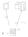
Fig. 1 is an explanatory drawing showing an image data output
system including an output apparatus embodying the present invention.
The image data output apparatus 10 includes a digital still camera 12 that
serves as an image data generating device that generates an image file,
and a printer 20 that serves as an image output apparatus. The image file
generated by the digital still camera 12 is sent to the printer 20 over a
cable CV or by inserting directly into the printer 20 the memory card MC
on which the image file is stored. The printer 20 performs image quality
adjustment with regard to the image data based on the read-in image file,
and the resulting image is output. Besides the printer 20, the output
apparatus may include a monitor 14 such as a CRT display or an LDC
display, a projector, or the like. The discussion below is based on a case
in which a printer 20 having an image quality adjuster and an image
output unit is used as an output apparatus and the memory card MC is
inserted directly in the printer 20.
Fig. 2 is a block diagram showing the basic construction of the
digital still camera 12. The digital still camera 12 of this embodiment
includes an optical circuit 121 that gathers optical information, an image
acquisition circuit 122 that acquires an image by controlling the optical
circuit, an image processing circuit 123 that performs processing to the
acquired digital image, and a control circuit 124 that controls the various
circuits described above. The control circuit 124 includes a memory not
shown. The optical circuit 121 includes a lens 125 that gathers light
information, an aperture 129 that regulates the amount of light, and a
CCD 128 that converts the information pertaining to the light passing
through the lens into image data.
The digital still camera 12 saves the acquired image on the memory
card MC. The image data stored by the digital still camera 12 is generally
saved in the JPEG format, but a different format may be used, such as the
TIFF format, the GIF format, the BMP format or the raw data format.
The digital still camera 12 includes a selection/determination
button used to set the various photo-taking conditions (aperture value,
shutter speed, exposure adjustment mode, photo-taking mode, etc.), and a
liquid crystal display 127. The liquid crystal display 127 is used when
previewing the photo image or setting the aperture value or other
parameters using the selection/determination button 126. The aperture
value can be set to a value falling within a predetermined prescribed range
in accordance with the model of the digital still camera 12, such as a
prescribed discrete value between 2 and 16 (2, 2.8, 4, 5.6, etc.). Normally
the F-number is used as the aperture value. Therefore, the aperture
decreases in size as the aperture value increases. The shutter speed can
also be set to a value falling within a prescribed range, such as to a value
between 1 / 15 seconds and 1/250 seconds. The exposure adjustment
mode can be set to one of several modes installed beforehand, such as
program auto (automatic adjustment mode), aperture priority mode,
shutter speed priority mode or manual mode. If program auto mode is
set, the exposure is set to a standard value by adjusting the aperture
value and the shutter speed automatically to standard values. If manual
mode is set, user-specified values for the aperture value and shutter speed
are used. A construction may be adopted in which where the aperture
value and shutter speed are set by the user, the exposure adjustment
mode using those set values is automatically selected. As the photo-taking
mode, one of several modes installed beforehand, such as standard
mode, human subject mode (portrait mode), scenery mode or night shot
mode may be selected in accordance with the type of photo subject or
other parameter. Where one photo-taking mode is specified by the user,
the relevant parameters (such as the aperture value and the lens focal
length) are set automatically in accordance with the specified photo-taking
mode. For example, where standard mode is specified as the photo-taking
mode, not only the aperture value but also other parameters related to
image data generation are set automatically. The standard photo-taking
conditions under which the aperture value is set to a standard value (for
example, the photo-taking conditions set when program auto mode is
selected as the exposure adjustment mode, or the photo-taking conditions
set when standard mode is selected as the photo-taking mode) are the
default photo-taking conditions for the digital still camera 12. The
standard photo-taking conditions are often used as the default settings
when the digital still camera 12 is purchased.
Where photo-taking is performed using the digital still camera 12,
the image data and image generating information are stored in the
memory card MC as an image file. The image generating information can
include the set values for parameters such as the aperture value used for
photo-taking (image data generation). The image generating information
will be described below.
B. Structure of image file:
Fig. 3 is an explanatory drawing showing in a conceptual fashion
the internal structure of an image file that can be used in this
embodiment. The image file GF includes an image data storage area 101
that stores image data GD and an image generating information storage
area 102 that stores image generating information GI. The image data GD
is stored in JPEG format, and the image generating information GI is
stored in TIFF format (a format in which data and data areas are specified
using tags), for example. The terms "file structure" and "data structure" in
this embodiment refer to the structure of files or data when such files or
data are stored in a storage device.
The image generating information GI is related to generation of the
image, or photo-taking, by an image data generating device such as the
digital still camera 12, and includes the set values for the following
parameters:
- aperture value
- shutter speed
- exposure time
- lens focal length
- exposure adjustment mode
- photo-taking mode
- manufacturer
- model name
- gamma value
The image file GF in this embodiment should basically include the
image data storage area 101 and the image generating information storage
area 102, and can have a file structure compatible with a standard file
format. The description below will assume a case in which the image file
GF pertaining to this embodiment is in the Exif file format.
An Exif file has a file structure compatible with an image file format
standard for digital cameras (Exif), and its specifications are established
by the Japan Electronics and Information Technology Industries
Association (JEITA). Similar to the conceptual diagram in Fig. 3, the Exif
file format includes a JPEG image data storage area that stores image
data in the JPEG format and an ancillary information storage area that
stores various information pertaining to the stored JPEG image data. The
JPEG image data storage area corresponds to the image data storage area
101 shown in Fig. 3, and the ancillary information storage area
corresponds to the image generating information storage area 102. Image
generating information pertaining to JPEG image, such as the date of
exposure, the aperture value and the shutter speed, are stored in the
ancillary information storage area.
Fig. 4 is an explanatory drawing showing an example of the data
structure of the ancillary information storage area 103. In the Exif file
format, hierarchical tags are used to identify data areas. Each data area
can contain multiple subordinate data areas that are specified by
subordinate tags. In Fig. 4, each area enclosed by a rectangle indicates a
data area, and the tag name is shown in the upper left-hand corner of the
area. This embodiment includes three data areas having the tag names
APP0, APP1 and APP2. The APP1 data area contains two data areas
having the tag names IFD0 and IFD1. The IFD0 data area contains three
data areas having the tag names PM, Exif and GPS. Data and data areas
are stored in accordance with a specified address or offset value, and
these addresses and offset values can be found using tag names. On the
side of the output apparatus, data corresponding to desired information
can be obtained by specifying an address or offset value corresponding to
the desired information.
Fig. 5 is an explanatory drawing showing an example of the data
structure (the tag names and parameter values) of the Exif data area,
which can be referred to by following the tag names in the order of APP1 -
IFD0 - Exif. While not shown in Fig. 5, the Exif data area can include a
data area having the tag name "MakerNote", and this MakerNote area can
further include other items of data, as shown in Fig. 4.
Parameter values corresponding to information such as the
exposure time, the aperture value, the exposure program, the lens focal
length and the photo scene type are stored in the Exif data area, as shown
in Fig. 5. The aperture value can be used as aperture information, and
the exposure program and photo scene type can be used as operation
mode information.
The exposure program identifies the exposure adjustment mode,
and is selected and set from among multiple values that include the
following four values, for example.
The photo scene type identifies the photo-taking mode, and is
selected and set from among standard mode, human subject mode
(portrait mode), scenery mode and night shot mode, for example.
Information associated with the image data is also stored in areas
other than the Exif data area in Fig. 4 if necessary. For example, the
manufacturer name and model name, which serve as information that
specify the image data generating device, are stored in the data area
having the tag name of IFD0.
C. Construction of image data output apparatus:
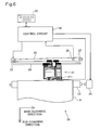
Fig. 6 is a block diagram showing the basic construction of the
printer 20 of this embodiment. The printer 20 can output images, and is,
for example, an inkjet printer that forms dot patterns by discharging ink
in the four colors of cyan (C), magenta (Mg), yellow (Y) and black (K) onto a
printing medium. Alternatively, an electrophotographic printer that forms
images by transferring and fusing toner onto a printing medium can also
be used. In addition to the four ink colors described above, the colors of
light cyan (LC) having a lower colorant concentration than cyan (C), light
magenta (LM) having a lower colorant concentration than magenta (Mg)
and dark yellow (DY) having a higher colorant concentration than yellow
(Y) can be used. Only black ink (K) may be used when monochrome
printing is performed, or red (R) and green (G) may be used. The type of
ink or toner used may be determined in accordance with the
characteristics of the images to be output.
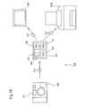
As shown in the drawing, the printer 20 includes a mechanism that
drives a print head 211 that is mounted on a carriage 21 and discharges
ink to form dots, a mechanism that uses a carriage motor 22 to drive the
carriage 21 forward and backward along the axial direction of a platen 23,
a mechanism that feeds printing paper P via a paper feed motor 24, and a
control circuit 30. These mechanisms enable the printer 20 to function as
an image output unit. The mechanism to move the carriage 21 forward
and backward along the axial direction of the platen 23 includes such
components as a moving axis 25 that movably supports the carriage 21
and is mounted parallel to the platen 23, a pulley 27 over which is
suspended a continuous-loop driving belt 26 disposed between the pulley
27 and a carriage motor 22, and a position sensor 28 that detects the
original position of the carriage 21. The mechanism to feed the printing
paper P includes such components as the platen 23, a paper feed motor
24 that causes the platen 23 to rotate, a paper feed auxiliary motor not
shown, and a gear train (omitted from the drawing) that transmits the
rotation of the paper feed motor 24 to the platen 23 and the paper feed
auxiliary motor.
The control circuit 30 appropriately controls the movement of the
paper feed motor 24 and the carriage motor 22, as well as the print head
211, while sending and receiving signals to and from the printer operation
panel 29. The printing paper P supplied to the printer 20 is set such that
it is grasped between the platen 23 and the paper feed auxiliary roller, and
is fed a prescribed amount in accordance with the rotation of the platen
23.
The carriage 21 has a print head 211, and can house an ink
cartridge containing usable inks. Nozzles (not shown) that discharge the
usable inks are disposed on the bottom surface of the print head 211.
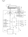
Fig. 7 is a block diagram showing the construction of the printer 20
with a focus on the control circuit 30 thereof. Disposed in the control
circuit 30 are a CPU 31, a PROM 32, a RAM 33, a memory card slot 34
that receives data from the memory card MC, a peripheral device I/O unit
(PIO) 35 that exchanges data with the paper feed motor 24 and the
carriage motor 22, for example, a drive buffer 37 and the like. The drive
buffer 37 is used as a buffer to supply dot ON/OFF signals to the print
head 211. These various internal circuit components are connected via a
bus 38, enabling data to be exchanged therebetween. Also disposed in the
control circuit 30 are a transmitter 39 that outputs a drive waveform
having a prescribed frequency and an output distribution unit 40 that
distributes the output from the transmitter 39 to the print head 211 in
accordance with a prescribed timing sequence.
The control circuit 30 outputs dot data to the drive buffer 37
according to a prescribed timing sequence in synchronization with the
movement of the paper feed motor 24 and the carriage motor 22. It also
reads an image file from the memory card MC, analyzes the ancillary
information, and performs image processing based on the image
generating information. In other words, the control circuit 30 functions as
an image quality adjuster. The sequence of operations performed by the
control circuit 30 will be explained in detail below.
D. Image processing in digital still camera:
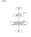
Fig. 8 is a flow chart showing the sequence of operations performed
in the digital still camera 12 to generate an image file GF .
The control circuit 124 of the digital still camera 12 (see Fig. 2)
generates image data GD in response to a photo-taking request, such as
the pressing of the shutter button (step S100). Where parameter values
such as the aperture value, exposure adjustment mode and photo-taking
mode are set, the image data is generated using these parameter values.
The control circuit 124 stores the generated image data GD and
image generating information GI on the memory card MC as an image file
GF (step S110) and terminates the processing routine. The image
generating information GI includes: parameter values used during image
generation, such as the shutter speed; parameter values that can be freely
set, such as the photo-taking mode and the exposure adjustment mode;
and parameter values that are set automatically, such as the
manufacturer and model name of the digital still camera 12. The image
data GD undergoes JPEG compression after being converted from the
RGB color space to the YCbCr color space, whereupon it is saved as an
image file GF.
By carrying out the above processing in the digital still camera 12,
the image data GD and the image generating information GI that includes
the various parameter values used during image data generation are set in
the image file GF.
E. Image processing in printer:
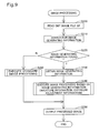
Fig. 9 is a flow chart showing the image processing routine carried
out in the printer 20 of this embodiment. The description below assumes
a case in which the memory card MC on which the image file GF is stored
in inserted directly in the printer 20. When the memory card MC is
inserted in the memory card slot 34, the CPU 31 of the control circuit 30
(see Fig. 7) reads the image file GF (see Fig. 3) from the memory card MC
(step S200). In step S210, the CPU 31 searches the ancillary information
storage area of the image file GF for the image generating information GI
indicating the information used during image data generation. Where the
image generating information GI is found (YES in step 220), the CPU 31
obtains and analyzes it (step 230). The CPU 31 then carries out the image
processing described below based on the analyzed image generating
information GI (step S240) and outputs the processed image (step S250),
whereupon the routine ends.
On the other hand, an image file generated using a drawing
application or the like does not have image generating information GI
containing such information as the aperture value. Where image
generating information GI is not found (NO in step S220), the CPU 31
carries out standard processing (step S260) and outputs the processed
image (step S250), whereupon the processing routine ends.
Fig. 10 is a flow chart showing the image processing routine
performed in step S240 of Fig. 9 based on the image generating
information. The CPU 31 of the control circuit 30 of the printer 20 (see
Fig. 7) extracts the image data GD from the read-out image file GF (step
S300).
The digital
still camera 12 saves the image data GD as a JPEG
format file as described above, in which the image data is saved using the
YCbCr color space. In step S310, the
CPU 31 performs calculation using
a 3 x 3 matrix S in order to convert the image data based on the YCbCr
color space to image data based on the RGB color space. This matrix
calculation uses the equation below, for example.
Where the color space of the image data generated by the digital still
camera 12 is larger than a prescribed color space, such as the sRGB color
space, for example, the RGB color space-based image data obtained in
step S310 may include value data outside the defined region of that RGB
color space. If the image generating information GI contains an
instruction to treat the data outside the defined region as valid data, the
data outside the defined region is saved as is, and image processing is
continued. If there is no instruction to treat the data outside the defined
region as valid data, such data is clipped to fall within the defined region.
For example, where the defined region is 0-255, values under 0 are
rounded to 0, and values of 256 or larger are rounded down to 255.
Where the color space that can be expressed by the image output unit is
not larger than a prescribed color space, such as the sRGB color space,
for example, it is preferred that the data be clipped to fall within the
defined color space regardless of the presence or absence of an instruction
in the image generating information GI. Such a case may include a
situation in which, for example, the image data is output to a CRT that
uses the sRGB color space as the expressible color space.
Next, in step S320, the CPU 31 performs gamma correction as well
as calculation using a matrix M, and converts the image data based on the
RGB color space to image data based on the XYZ color space. The image
file GF can include the gamma value and color space information present
during image generation. If the image generating information GI contains
these items of information, the CPU 31 obtains the gamma value for the
image data from the image generating information GI and subjects the
image data to gamma conversion processing using the obtained gamma
value. Furthermore, the CPU 31 obtains the color space information for
the image data from the image generating information GI and performs
matrix calculation regarding the image data using the matrix M for that
color space. If the image generating information GI does not include a
gamma value, gamma conversion processing can be carried out using a
standard gamma value. If the image generating information GI does not
include color space information, matrix calculation can be performed
using a standard matrix M. For this standard gamma value and matrix
M, the gamma value and matrix corresponding to the sRGB color space
may be used, for example.
This matrix calculation is performed using the equation shown
below, for example.
The color space for the image data obtained after matrix calculation
is the XYZ color space. The XYZ color space is an absolute color space,
and is a device-independent color space that does not depend on any
particular device, such as a digital still camera or a printer.
Consequently, by performing color space conversion using the XYZ color
space, device-independent color matching can be achieved.
Next, in step S330, the
CPU 31 performs calculation using a matrix
N
-1, as well as reverse gamma correction, and converts the image data
based on the XYZ color space to image data based on the wRGB color
space. To carry out gamma correction, the
CPU 31 obtains the printer's
gamma value from the
PROM 32, and performs reverse gamma conversion
processing of the image data using the reciprocal of the obtained gamma
value. In addition, the
CPU 31 obtains from the
PROM 32 the matrix N
-1
corresponding to the conversion from the XYZ color space to the wRGB
color space and performs matrix calculation regarding the image data
using this matrix N
-1. This matrix calculation uses the equation shown
below, for example.
In step S340, the CPU 31 executes the automatic image quality
adjustment process. This process in the embodiment executes automatic
sharpness adjustment of the image data using the image generating
information contained in the image file GF, particularly the aperture value
which serves as aperture information, and the exposure program
parameter value which serves as operation mode information. Sharpness
adjustment and automatic image quality adjustment processing will be
described later.
In step S350, the CPU 31 executes CMYK color conversion
processing and halftone processing for printing. In CMYK color
conversion processing, the CPU 31 converts the color space of the image
data from the wRGB color space to the CMYK color space with reference to
a lookup table (LUT) used for conversion from the wRGB color space to the
CMYK color space and stored in the PROM 32. In other words, image data
consisting of RGB tone values is converted to image data used by the
printer 20 including, for example, six tone values of C (Cyan), Mg
(Magenta), Y (Yellow), K (Black), LC (Light Cyan) and LM (Light Magenta).
In halftone processing, the CPU 31 executes so-called halftone
processing, and generates halftone image data from the color-converted
image data. This halftone image data is rearranged in the order in which
it is to be forwarded to the drive buffer 37 (see Fig. 7), ultimately becoming
print data, whereupon this processing routine is ended. The image data
that underwent processing in this routine is then output in the image
processing routine of step S250 shown in Fig. 9.
F. Embodiments of sharpness adjustment process:
For sharpness adjustment, an unsharp masking process may be
employed. Figs. 11(a)-11(d) are conceptual drawings that describe a
sharpness adjustment method that uses an unsharp mask. The stages of
sharpness adjustment are described sequentially using the brightness of
pixels arranged in a straight line.
Fig. 11(a) shows the original data ODATA prior to sharpness
adjustment. The vertical axis indicates the brightness value for each
pixel, and in this example, the brightness may have a value between 0 and
100. The horizontal axis indicates the pixel position, and each mark
indicates one pixel among multiple pixels arranged in a straight line. In
other words, marks indicating pixels arranged in a straight line are
aligned along the horizontal direction in accordance with the order of
arrangement of the pixels. Sharpness adjustment will be described using
as the original data ODATA the data for an area in which the brightness
values change in a stair-step fashion in this way.
In order to increase sharpness, a method using an unsharp mask
can be employed. In this method, data having dull changes in brightness
(i.e., unsharp data) is prepared and the changes in brightness are
enhanced by subtracting the unsharp data from the original data.
Unsharp data can be obtained by averaging the brightness values of each
pixel of the original data using the brightness values of the surrounding
pixels. This averaging method, may be performed by computing an
average of the brightness value of the target pixel and the average values
of the surrounding pixels. Alternatively, an averaging method may be
employed in which greater weight is given to the brightness values of
closer pixels having a smaller pixel distance to the target pixel. A
Gaussian function focusing on the target pixel may be used for this
weighting function (unsharp mask) because the pixels of actual image
data are distributed on a two-dimensional plane, a two-dimensional
Gaussian function is used.
Fig. 11(b) shows the brightness values of the unsharp data UDATA
generated using an unsharp mask. In comparison with the original data
ODATA, the changes in the brightness values are less pronounced.
Fig. 11(c) shows difference data DIFF derived by subtracting the
unsharp data UDATA from the original data ODATA. Sharp data in which
the changes in brightness values are enhanced can be obtained by adding
to the original data ODATA the product obtained by multiplying this
difference data DIFF by a prescribed coefficient G. Fig. 11(d) shows the
brightness values of sharp data obtained using various different
coefficients G. S1 shows sharp data using a relatively small coefficient
G1, while S2 shows sharp data using a relatively large coefficient G2. In
both S1 and S2, the changes in brightness are steeper than they are in
the original data, making image sharpness clearer. Furthermore, as can
be seen from a comparison between S1 and S2, the intensity of sharpness
adjustment can be increased as the coefficient G increases. If the
coefficient G is set to "0", the original data ODATA matches the sharp
data, and sharpness adjustment is not performed.
Sharpness reduction may be attained by using the unsharp data
UDATA described above as the data after the sharpness adjustment. In
this case, the changes in brightness of the obtainable unsharp data
decline in magnitude as the size of the unsharp mask increases.
By adjustment the amount of the coefficient G or the size of the
unsharp mask as described above, the degree of sharpness adjustment
can be changed.
G. Embodiments of automatic image quality adjustment process:
G1. First embodiment of automatic image quality adjustment process:
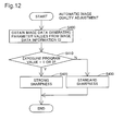
Fig. 12 is a flow chart showing an automatic image quality
adjustment routine of this embodiment in step S340 of Fig. 10. The CPU
31 analyzes the image generating information GI and obtains the aperture
value and exposure program value (step S400). In step S410, it is
determined whether or not the aperture value used for image data
generation was manually set. In this example, for manual setting, the
user can choose either of manual exposure adjustment mode and aperture
priority exposure adjustment mode. In manual mode, the exposure
program value (see Fig. 5) is "1", while in aperture priority mode, it is "3".
The CPU 31 determines whether or not the exposure program value is "1"
or "3".
If it is determined that the exposure adjustment mode is neither
manual mode nor aperture priority mode (No in step S410), the CPU 31
performs image adjustment using a standard degree of sharpness
adjustment in step S430. If the exposure adjustment mode is either
manual mode or aperture priority mode (Yes in step S410), because the
aperture value is set manually, it is determined that the user intends to
set the depth of field of the image to a preferred level. In this case, if the
aperture is small (i.e., the aperture value is large), the CPU 31 performs in
step S420 image quality adjustment wherein the degree of sharpness
adjustment is high.
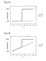
Fig. 13 is an explanatory drawing showing the relationship between
the degree of sharpness adjustment and the aperture value. The vertical
axis in each chart indicates the degree of sharpness adjustment (termed
the "sharpness intensity" below), wherein the adjusted sharpness
increases in intensity as the axis value increases. The horizontal axis in
each chart indicates the aperture value F. STD indicates the sharpness
intensity of the image quality adjustment where the aperture value is set
in the digital still camera 12 under standard photo-taking conditions
(termed "standard sharpness intensity" below), while C1 indicates the
sharpness intensity of the image quality adjustment where the aperture
value is set manually (termed "high sharpness intensity" below). In this
embodiment, the standard sharpness intensity STD is used where the
exposure adjustment mode is program auto or shutter speed priority mode
(see step S430 in Fig. 12) and the high sharpness intensity C1 is used
where the exposure adjustment mode is manual mode or aperture priority
mode (see step S420 in Fig. 12). The "standard photo-taking conditions"
for the digital still camera 12 refers to the default photo-taking conditions
in effect when the digital still camera 12 is shipped from the factory, and
are normally equivalent to the "program auto" photo-taking conditions.
Another arrangement may also be adopted in which image quality
adjustment is performed using a sharpness intensity different from the
standard sharpness intensity when the mode is shutter speed priority
mode.
The high sharpness intensity C1 is set such that it is larger than the
standard sharpness intensity STD when the aperture value is "8" or
higher. As a result, where the user sets the aperture value to a large value
(i.e., to a small aperture) in order to obtain sharper image output, sharper
image output can be effectively obtained. The prescribed aperture value at
which the high sharpness intensity C1 becomes larger than the standard
sharpness intensity STD is not limited to "8", and may be preset to any
desired value. For example, by setting it to "4", sharper images can be
output, and by setting it to "11", softer images can be output.
For the standard sharpness intensity STD, a value preset to obtain
output results for images generated under standard operating conditions
for the digital still camera 12 (e.g., program auto mode) can be used.
Alternatively, the standard sharpness intensity STD may be adjusted for
each image in accordance with the results of image sharpness analysis for
each image in order to obtain an image sharpness value close to the
standard value. Image sharpness can be obtained by averaging edge
amounts for each pixel, where the edge amount for one pixel is defined as
the absolute value of the difference in brightness between that pixel and
the brightness of a prescribed surrounding pixel. Alternatively, sharpness
may be defined as the value obtained from averaging pixel values where
pixels having a large edge amount (i.e., pixels thought to be equivalent to
the edge in the image) are given a greater weighting. Furthermore, the
standard sharpness intensity STD may indicate not to perform sharpness
adjustment. Where the standard sharpness intensity STD is set according
to various methods as described herein, the high sharpness intensity C1
becomes larger than the standard sharpness intensity when the aperture
value is set to fall within a prescribed range, in this example, where the
aperture value is "8" or higher.
The high sharpness intensity C1 used during image quality
adjustment when manual aperture setting is selected can be determined
as the value that will produce the optimal image output results; the
optimal results may be selected by comparing the image data obtained
through image quality adjustment for high sharpness and the image data
obtained through image quality adjustment for standard sharpness via
quantitative evaluation of the image sharpness and the perceptual
evaluation of the output results. For example, for the same image data,
the high sharpness intensity C1 can be determined by comparing the
output results where the exposure program parameter value is set to "3"
(aperture priority mode) with the output results where the exposure
program parameter value is set to "2" (program auto). Where the image
data generating device has an operation mode in which the various
parameter values used during image generation including the aperture
value and the exposure can be automatically adjusted to standard values,
the degree of sharpness adjustment can be checked by comparing an
output result when this operation mode is set with another output result
from the same original image when aperture priority mode is set.
Although in this embodiment the image quality adjustment is performed
using the same sharpness intensity when the exposure adjustment mode
is manual mode or aperture priority mode, the sharpness intensity used
during image quality adjustment may differ depending on the active
exposure adjustment mode.
G2. Second embodiment of automatic image quality adjustment process:
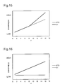
Fig. 14 is an explanatory drawing showing the relationship between
the degree of sharpness adjustment and the aperture value in a second
embodiment of the automatic image quality adjustment process. The
horizontal and vertical axes indicate the same variables, and STD and C1
represent the same values, as in connection with Fig. 13.
In the second embodiment, unlike in the first embodiment shown in
Fig. 13, the standard sharpness intensity STD increases continuously as
the aperture value increases. As a result, differences in sharpness due to
the aperture value can be reflected in image quality adjustment for
standard sharpness as well. Furthermore, by increasing the high
sharpness intensity C1 used when the aperture value equals or exceeds a
prescribed value (in this example, "8") to a value larger than the standard
sharpness intensity STD, the wishes of a user who desires a sharper
output can be met. Another arrangement may be adopted in which the
standard sharpness intensity STD increases in a stair-step, i.e.
incrementally, over multiple increments, rather than continuously, as the
aperture value increases.
G3. Third embodiment of automatic image quality adjustment process:
Fig. 15 is an explanatory drawing showing the relationship between
the degree of sharpness adjustment and the aperture value in a third
embodiment of the automatic image quality adjustment process. In the
third embodiment, unlike in the first embodiment shown in Fig. 13, the
high sharpness intensity C1 increases continuously as the aperture value
increases where the aperture value equals or exceeds a prescribed value
("8" in this example). As a result, sharpness intensity processing can be
performed with more precision based on the aperture value. Another
arrangement may also be adopted in which the high sharpness intensity
C1 increases incrementally over multiple increments, rather than
continuously, as the aperture value increases.
G4. Fourth embodiment of automatic image quality adjustment process:
Fig. 16 is an explanatory drawing showing the relationship between
the degree of sharpness adjustment and the aperture value in a fourth
embodiment of the automatic image quality adjustment process. In the
fourth embodiment, unlike in the first embodiment shown in Fig. 13, the
high sharpness intensity C1 increases continuously with increases in the
aperture value over the entire range of possible aperture values. As a
result, sharpness enhancement processing can be performed with more
precision based on the aperture value. Another arrangement may also be
adopted in which the high sharpness intensity C1 increases incrementally
over multiple increments, rather than continuously, as the aperture value
increases.
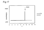
G5. Fifth embodiment of automatic image quality adjustment process:
Fig. 17 is an explanatory drawing showing the relationship between
the degree of sharpness adjustment and the aperture value in a fifth
embodiment of the automatic image quality adjustment process. In the
fifth embodiment, when the aperture value is at the maximum usable
aperture value for the device that generates the image, the high sharpness
intensity C1 becomes larger than the standard sharpness intensity STD.
For example, in the example shown in Fig. 17, the maximum possible
aperture value is 11, and where the aperture value is 11, the high
sharpness intensity C1 becomes larger than the standard sharpness
intensity STD. As a result, the user can output sharp images through the
simple operation of setting the aperture value to the maximum value.
The maximum possible aperture value is determined in accordance
with the model of the digital still camera 12 (or more generally, the model
of the image data generating device). Where the image generating
information GI of the image file GF includes the maximum possible
aperture value, the CPU 31 (see Fig. 7) can obtain that value and adjust
the sharpness intensity in accordance therewith. Alternatively, it is
acceptable if an aperture value table composed of image data generating
devices and the maximum possible aperture values for such devices is
stored in a memory such as the PROM 32 (see Fig. 7). Where the image
generating information GI includes as information pertaining to the
maximum possible aperture value the manufacturer name and model
name, for example, the CPU 31 can obtain the maximum possible
aperture value from the aperture value table. It is also acceptable if the
aperture value table is obtained online over a network or the like. This
would enable the aperture value table to be updated with the most recent
pertinent information. In this way, information specifying the model of the
image generating device could be used as information pertaining to the
maximum possible aperture value.
H. Construction of image data output system using image data
processing device:
Fig. 18 is an explanatory drawing showing another image data
output system including the image data processing apparatus embodying
the present invention. The image data output system 10B includes a
digital still camera 12 that functions as an image data generating device to
generate an image file, a computer PC that executes image quality
adjustment based on the image file, and a printer 20B that functions as
an image data output apparatus to output images. The computer PC is an
ordinary personal computer that functions here as an image data
processing device. In addition to the printer 20B, the functions of an
image data output apparatus may be performed by a monitor 14B such as
a CRT display or an LCD display, or a projector or the like. In the
description below, the printer 20B is used as the image data output
apparatus. This embodiment differs from the embodiment of the image
data output system described above (see Fig. 1) in that the image data
processing device incorporating an image quality adjuster and the image
data output device incorporating an image output unit are independent
components. The computer PC that functions as the image data
processing device and the printer incorporating an image output unit can
be collectively referred to as the "output apparatus" below.
The image file generated by the digital still camera 12 is sent to the
computer PC over the cable CV or by direct insertion of the memory card
MC on which the image file is stored into the computer PC. The computer
PC executes image adjustment processing of the image data based on the
read-in image file. The image data generated from the image quality
adjustment process is sent to the printer 20B via the cable CV and is
output by the printer 20B.
The computer PC includes a CPU 150 that executes the program to
implement the above image quality adjustment process, a RAM 151 in
which is temporarily stored the results of calculation by the CPU 150,
image data or the like, and a hard disk drive (HDD) 152 on which is stored
data required for image quality adjustment processing, such as the image
quality adjustment program, a lookup table, an aperture value table or the
like. The CPU 150, RAM 151 and HDD 152 function collectively as an
image quality adjuster. The computer PC further includes a memory card
slot 153 used for mounting of the memory card MC and an I/O terminal
154 used for connecting the connecting cable from the digital still camera
12 or the like.
The image file GF generated by the digital still camera 12 is supplied
to the computer PC via a cable or the memory card MC. When an image
data processing application program such as an image retouching
application or a printer driver is activated, the CPU 150 executes an image
processing routine to process the read-in image file (see Fig. 9). It is also
acceptable if the image data processing application program is activated
automatically when the memory card MC is inserted in the memory card
slot 153 or the digital still camera 12 is connected to the I/O terminal 154
via a cable.
Instead of being output in step S250 of the image processing routine
(see Fig. 9), the image data processed by the CPU 150 is sent to the
printer 20B or other image data output apparatus, and the image data
output apparatus that receives the image data outputs the image.
In this embodiment, because image processing is carried out using
an image quality adjuster that is included in the computer PC, an image
data output apparatus that does not incorporate an image quality adjuster
can be used. Alternatively, where the image data output apparatus
includes an image quality adjuster, the computer PC may send the image
data to the image data output apparatus without subjecting it to image
processing, and image processing is performed by the image quality
adjuster of the image data output apparatus.
In the embodiments described above, because image quality is
adjusted using the image generating information GI included in the image
file GF, high-quality output results that reflect the user's preferences can
be easily obtained. In particular, image data generated after user
adjustment of the aperture value can be output after appropriate
sharpness adjustment.
The present invention is not limited to these embodiments, and may
be implemented in various forms within the essential scope of the
invention. The variations described below, for example, are possible.
I. Variations:
I1. First variation:
Where the image file GF does not include gamma data or color space
information for the image data, the color space conversion process of the
image processing routine shown in Fig. 10 (steps S320 and S330) can be
omitted. Fig. 19 is a flow chart showing an image processing routine in
which the color space conversion process is omitted. In step 510, the
image data extracted in step S500 is converted from image data based on
the YCbCr color space to image data based on the RGB color space. Next,
in step S520, automatic image quality adjustment is performed using the
image data obtained in step S510. In step S530, CMYK color conversion
processing and halftone processing are carried out for purposes of
printing.
I2. Second variation:
In the above embodiments, the automatic image quality adjustment
process was performed after color space conversion, but it is acceptable if
color space conversion is performed after automatic image quality
adjustment. For example, image processing may be carried out in
accordance with the flow chart shown in Fig. 20.
I3. Third variation:
In the above embodiments, a printer is used as the image output
unit, but an image output unit other than a printer may be used. Fig. 21
is a flow chart showing an image processing routine based on image
generating information and executed using a CRT as an image output
unit. It differs from the flow chart of Fig. 10, in which the printer is used
as the image output unit, in that CMYK conversion processing and
halftone processing are omitted. Furthermore, because the CRT can
reproduce the RGB color space of the image data obtained via matrix
calculation S, color space conversion is also omitted. Where the RGB
color space-based image data obtained in step S610 includes data outside
the defined region of the RGB color space, step S620 is performed after
such data is clipped. Where the color space that can be used by the
image output unit is different from the RGB color space, color space
conversion to convert the data to a color space that can be used by the
image output unit is performed (just as CMYK color conversion is carried
out when a printer was used as the image output unit), and the resulting
images are output by the image output unit.
I4. Fourth variation:
In the above embodiments, images generated in the two operation
modes (manual mode and aperture priority mode) where the aperture
value is manually set by the user undergo identical sharpness
adjustment. Alternatively, it is acceptable if image quality adjustment is
carried out such that the sharpness is different for each of multiple
operation modes where the aperture value is manually set. In this case as
well, when the aperture value is set to fall within a prescribed range of
relatively high aperture values, the sharpness intensities for the various
operation modes are set to be higher than the standard sharpness
intensity STD. The prescribed range of relatively high values may be
different for each operation mode. This enables image quality adjustment
appropriate to the operation mode to be carried out. Furthermore, where
there are multiple operation modes in which the aperture value is
automatically adjusted, image quality adjustment may be performed such
that the sharpness intensity is different for each operation mode. For
example, where the photo scene type parameter value including operation
mode information (see Fig. 5) is set to human subject mode (portrait mode)
in order to take a photo of a human subject, it is preferred that image
quality adjustment be performed using a sharpness intensity that is lower
than the standard sharpness intensity STD. This would enable a softer
image of a human subject (i.e., portrait) to be output; with regard to the
relationship between the sharpness intensity and the aperture value, it is
acceptable if the sharpness intensity is always lower than the standard
sharpness intensity STD regardless of the aperture value, or if the
sharpness intensity becomes lower than the standard sharpness intensity
STD only if the aperture value is set to fall within a prescribed range.
Another arrangement may be adopted in which sharpness adjustment is
not performed for an image taken by the human subject mode. This
would enable image processing in human subject mode (portrait mode) to
be simplified. Where the photo scene type parameter value is set to
scenery mode for photo-taking of a natural landscape, it is preferred that
image quality adjustment be performed using a sharpness that is higher
than the standard sharpness intensity STD. This would enable sharper
landscape images to be output. In either case, it is preferred that the
degree of sharpness adjustment increase as the aperture value increases.
I5. Fifth variation:
In the above embodiments, the exposure program or the photo
scene type are used as operation mode information, but the operation
mode information pertaining to the present invention is not limited to
these items of information, and any information that includes information
regarding the operation of the image generating device for image
generation is acceptable.
I6. Sixth variation:
The sharpness adjustment process can be executed with regard to
all pixels, but it is acceptable if it is selectively executed only for pixels
having a relatively large edge amount. This would enable sharpness
adjustment to be performed without having to perform correction for
pixels that are thought not to correspond to the edges in the image.
Moreover, where the sharpness is increased during sharpness adjustment
using an unsharp mask, it is acceptable if the degree of sharpness
adjustment is adjusted not only by using a coefficient G but also by
adjusting the size of the unsharp mask.
I7. Seventh variation:
In the above embodiments, the image file GF is described using the
example of a file in the Exif format, but the image file format of the present
invention is not limited to this format. In other words, any image file that
includes the image data generated by the image data generating device
and the image generating information GI that describes the image data
generation conditions (information) may be used. This type of file would
enable the image data generated by the image data generating device to be
output from the output apparatus after appropriate automatic adjustment
of the image quality.
I8. Eighth variation:
The values for the variables matrix S, N-1 and M in the equations
above are only examples, and may be changed appropriately in
accordance with the color space on which the image file is based, the color
space that can be used by the image output unit or the like.
I9. Ninth variation:
In the above embodiments, the image data generating device is
described using the example of the digital still camera 12, but the image
file may alternatively be generated using an image data generating device
such as a scanner or a digital video camera. Where the image data
generating device incorporates an image quality adjuster (for example,
where the digital still camera 12 incorporates an image quality adjuster), it
is acceptable if sharpness adjustment processing is carried out within the
image generating device and the processed image data is sent directly to
an image output apparatus such as a printer or a monitor.
I10. Tenth variation:
The above embodiments are described as an example in which the
image data GD and the image generating information GI are contained in
the same image file GF, but it is not essential that the image data GD and
the image generating information GI be stored in the same file. In other
words, it is sufficient if the image data GD and the image generating
information GI are associated with each other in some way. For example,
it is acceptable if association data that associates the image data GD and
the image generating information GI is generated, one or more items of
image data and the associated image generating information GI are stored
in mutually independent files, and processing of the image data GD is
performed with reference to the associated image generating information
GI. In this case, although the image data GD and the image generating
information GI are stored in different files, at the moment image
processing that uses the image generating information GI is to begin, the
image data GD and the image generating information GI form an
indivisible unit, and can be considered to be substantially stored in the
same file. In other words, the form in which the image data GD and the
image generating information GI are associated to each other at the
moment of image processing at least is included in the scope of the image
file GF of this embodiment. Furthermore, moving image files stored on an
optical disk medium such as a CD-ROM, CD-R, DVD-ROM, DVD-RAM or
the like are included herein.
INDUSTRIAL APPLICABLITY
This invention may be applied in a personal computer, printer,
facsimile machine, digital camera or other type of image processing
apparatus.