CN1663251A - Output image adjustment of image data - Google Patents
Output image adjustment of image data Download PDFInfo
- Publication number
- CN1663251A CN1663251A CN038139162A CN03813916A CN1663251A CN 1663251 A CN1663251 A CN 1663251A CN 038139162 A CN038139162 A CN 038139162A CN 03813916 A CN03813916 A CN 03813916A CN 1663251 A CN1663251 A CN 1663251A
- Authority
- CN
- China
- Prior art keywords
- image
- image data
- information
- sharpness
- aperture
- Prior art date
- Legal status (The legal status is an assumption and is not a legal conclusion. Google has not performed a legal analysis and makes no representation as to the accuracy of the status listed.)
- Granted
Links
Images


Classifications
-
- H—ELECTRICITY
- H04—ELECTRIC COMMUNICATION TECHNIQUE
- H04N—PICTORIAL COMMUNICATION, e.g. TELEVISION
- H04N1/00—Scanning, transmission or reproduction of documents or the like, e.g. facsimile transmission; Details thereof
- H04N1/46—Colour picture communication systems
- H04N1/56—Processing of colour picture signals
- H04N1/60—Colour correction or control
- H04N1/6083—Colour correction or control controlled by factors external to the apparatus
- H04N1/6086—Colour correction or control controlled by factors external to the apparatus by scene illuminant, i.e. conditions at the time of picture capture, e.g. flash, optical filter used, evening, cloud, daylight, artificial lighting, white point measurement, colour temperature
-
- H—ELECTRICITY
- H04—ELECTRIC COMMUNICATION TECHNIQUE
- H04N—PICTORIAL COMMUNICATION, e.g. TELEVISION
- H04N1/00—Scanning, transmission or reproduction of documents or the like, e.g. facsimile transmission; Details thereof
- H04N1/40—Picture signal circuits
- H04N1/409—Edge or detail enhancement; Noise or error suppression
- H04N1/4092—Edge or detail enhancement
-
- H—ELECTRICITY
- H04—ELECTRIC COMMUNICATION TECHNIQUE
- H04N—PICTORIAL COMMUNICATION, e.g. TELEVISION
- H04N2201/00—Indexing scheme relating to scanning, transmission or reproduction of documents or the like, and to details thereof
- H04N2201/32—Circuits or arrangements for control or supervision between transmitter and receiver or between image input and image output device, e.g. between a still-image camera and its memory or between a still-image camera and a printer device
- H04N2201/3201—Display, printing, storage or transmission of additional information, e.g. ID code, date and time or title
- H04N2201/3225—Display, printing, storage or transmission of additional information, e.g. ID code, date and time or title of data relating to an image, a page or a document
- H04N2201/3252—Image capture parameters, e.g. resolution, illumination conditions, orientation of the image capture device
Landscapes
- Engineering & Computer Science (AREA)
- Multimedia (AREA)
- Signal Processing (AREA)
- Image Processing (AREA)
- Facsimile Image Signal Circuits (AREA)
- Studio Devices (AREA)
- Television Signal Processing For Recording (AREA)
Abstract
Description
技术领域technical field
本发明涉及的一种调整图象数据的图象质量的图象调整技术。The present invention relates to an image adjustment technique for adjusting image quality of image data.
背景技术Background technique
由数码相机(DSC)及数码摄象机(DVC)等生成的图象数据的图象质量,可以在个人计算机上使用图象修描应用程序任意调整。在图象修描应用程序中,一般地说,具有自动调整图象数据的图象质量的图象调整功能,利用该图象调整功能,就能提高输出装置输出的图象数据的图象质量。作为图象数据的输出装置,例如有CRT、LCD、打印机、投影机、电视机等,它们已经广为人知。The image quality of image data generated by digital still cameras (DSC) and digital video cameras (DVC), etc., can be adjusted arbitrarily using image retouching applications on a personal computer. Generally speaking, in the image retouching application program, there is an image adjustment function for automatically adjusting the image quality of image data, and by using this image adjustment function, the image quality of the image data output by the output device can be improved. . As output devices for image data, there are, for example, CRTs, LCDs, printers, projectors, televisions, etc., which are widely known.
另外,在控制输出装置之一的打印机的动作的打印驱动器中,也具有自动调整图象数据的图象质量的功能,利用这种打印驱动器,也能提高打印的图象数据的图象质量。In addition, the printer driver that controls the operation of the printer, one of the output devices, also has a function of automatically adjusting the image quality of image data, and this printer driver can also improve the image quality of printed image data.
可是,在由这些图象修描应用程序及打印驱动器提供的图象质量自动调整功能中,是以具有通常的图象质量特性的图象数据为基准实施图象质量校正的。而由于成为图象处理对象的图象数据,是在各种各样的条件下生成的,所以即使统一实施图象质量自动调整功能,也往往不能很好地提高图象质量。However, in the image quality automatic adjustment functions provided by these image retouching applications and printer drivers, image quality correction is performed based on image data having normal image quality characteristics. On the other hand, since the image data to be image processed is generated under various conditions, even if the image quality automatic adjustment function is implemented uniformly, the image quality cannot be improved well.
例如,在输出风景及纪念摄影等的图象时,最理想的是从主体到背景,整个画面都是对准焦距的鲜明的图象。因此,常常必须生成缩小光圈(加大光圈值),将动作方式、例如曝光调整方式,设定为优先利用用户设定的光圈值的光圈优先方式或手动方式的图象数据。可是,对于这种图象数据,即使进行以具有普通的图象质量特性的图象数据为基准的图象质量修正后,也往往得不到足够的锐度。此外,这种问题,不仅在DSC中存在,它还是DVC等其它图象数据生成装置的共同的问题。For example, when outputting images such as landscapes and commemorative photographs, it is ideal that the entire screen be a sharp image that is in focus from the subject to the background. Therefore, it is often necessary to generate image data in which the aperture is reduced (increases the aperture value), and the operation method, such as the exposure adjustment method, is set to the aperture priority method or the manual method in which the aperture value set by the user is given priority. However, for such image data, sufficient sharpness cannot always be obtained even after image quality correction based on image data having ordinary image quality characteristics is performed. In addition, this kind of problem exists not only in DSC, but is also a common problem in other image data generating devices such as DVC.
发明内容Contents of the invention
本发明旨在解决上述问题,目的在于根据一个个图象数据适当地自动调整图象质量。The present invention aims to solve the above-mentioned problems, and aims at automatically adjusting image quality appropriately and automatically in accordance with individual image data.
为了至少解决上述问题中的一部分,采用本发明的图象处理装置,是利用图象生成部生成的图象数据和至少包含所述图象数据生成时的光圈信息、动作方式信息的同时,还利用与所述图象数据相关的图象生成信息,输出图象的图象处理装置;具有根据所述图象生成信息包含的所述光圈信息和所述动作方式信息,调整所述图象数据的锐度的图象质量调整部。In order to solve at least part of the above-mentioned problems, the image processing device of the present invention uses the image data generated by the image generating unit and at least includes aperture information and operation mode information when the image data is generated, and also An image processing device for outputting an image by using image generation information related to the image data; and adjusting the image data according to the aperture information and the operation mode information included in the image generation information The sharpness of the image quality adjustment section.
采用本发明的图象处理装置,可以根据图象生成时的光圈信息和动作方式信息,对图象数据的锐度进行适当调整。With the image processing device of the present invention, the sharpness of the image data can be properly adjusted according to the aperture information and the operation mode information when the image is generated.
在所述图象处理装置中,所述图象质量调整部,最好在根据所述动作方式信息判断是否实施调整所述图象数据的锐度的图象质量调整的同时,还在断定要实施所述图象质量调整时,根据所述光圈信息,决定锐度调整的程度。In the image processing device, it is preferable that the image quality adjustment unit determines whether to perform image quality adjustment for adjusting the sharpness of the image data based on the operation mode information, and also determines whether to perform image quality adjustment to adjust the sharpness of the image data. When implementing the image quality adjustment, the degree of sharpness adjustment is determined according to the aperture information.
这样,能够根据动作方式,适当地进行是否实施调整锐度的图象质量调整的判断。进而能够根据光圈信息,适当地决定锐度调整的程度。In this way, it is possible to appropriately determine whether to perform image quality adjustment for adjusting sharpness according to the operation method. Furthermore, the degree of sharpness adjustment can be appropriately determined based on the aperture information.
在所述各图象处理装置中,所述图象质量调整部,可以根据所述动作方式信息,判断所述图象数据生成时的图象生成部的动作方式是不是肖像动作方式。在断定所述动作方式是肖像方式时,最好实施a)不实施所述图象质量调整和b)实施比在所述图象生成部的标准摄影条件下设定的所述光圈值弱的锐度调整中的某一种处理。In each of the above-mentioned image processing apparatuses, the image quality adjustment unit may determine whether the operation mode of the image generation unit at the time of generating the image data is a portrait operation mode based on the operation mode information. When it is determined that the operation mode is the portrait mode, it is preferable to perform a) not perform the image quality adjustment and b) perform an aperture value weaker than the aperture value set under the standard shooting conditions of the image generating unit. One of the processing in sharpness adjustment.
这样,可以根据图象生成部用肖像方式生成的图象数据,输出柔和的图象。In this way, a soft image can be output based on the image data generated by the image generating unit in the portrait mode.
在所述各图象处理装置中,所述图象质量调整部,在从所述光圈信息取得所述图象数据生成时使用的光圈值的同时,还能判断所述光圈值是不是由用户手动设定的。在断定所述光圈值是由用户手动设定的情况下,在所述光圈值被设定在可以取得所述光圈值的全部范围中至少一部分范围内时,最好实施比在所述图象生成部的标准条件下设定所述光圈值时强的锐度调整。In each of the above image processing apparatuses, the image quality adjustment unit acquires the aperture value used when the image data is generated from the aperture information, and also determines whether the aperture value is determined by the user. set manually. In the case where it is determined that the aperture value is manually set by the user, when the aperture value is set within at least a part of the entire range in which the aperture value can be obtained, it is preferable to perform Generates strong sharpness adjustments when setting the f-stop value under standard conditions of the section.
这样,可以更适当地调整调节光圈值后生成的图象数据的锐度。此外,光圈值通常是F值,光圈值越大,光圈越小。Thus, the sharpness of the image data generated after adjusting the aperture value can be adjusted more appropriately. In addition, the aperture value is usually an F value, and the larger the aperture value, the smaller the aperture.
在所述各图象处理装置中,所述强锐度调整,最好在所述光圈值在所定值以上时实施。In each of the above image processing devices, it is preferable that the sharpness adjustment is performed when the aperture value is equal to or greater than a predetermined value.
这样,可以更鲜明地调整将光圈值设定成所定值以上后生成的图象数据的图象质量。In this way, the image quality of image data generated by setting the aperture value to a predetermined value or more can be adjusted more clearly.
在所述各图象处理装置中,所述强锐度调整中的锐度调整的程度,最好是所述光圈值越大越强。In each of the above image processing devices, it is preferable that the degree of sharpness adjustment in the strong sharpness adjustment is stronger as the aperture value is larger.
这样,可以更鲜明地调整将光圈值设定得比较大后生成的图象数据的图象质量。In this way, the image quality of image data generated by setting the aperture value to a relatively large value can be adjusted more clearly.
在所述各图象处理装置中,所述图象生成信息,进而还包括有关在生成所述图象数据的图象数据生成部中可以利用的光圈值的最大值的信息:所述强锐度调整,最好在所述光圈值是所述光圈值的最大值时实施。In each of the image processing devices, the image generation information further includes information on the maximum value of the aperture value that can be used in the image data generation unit that generates the image data: the sharp The degree adjustment is preferably performed when the aperture value is the maximum value of the aperture value.
这样,可以更鲜明地调整将光圈值设定成最大值后生成的图象数据的图象质量。In this way, the image quality of image data generated by setting the aperture value to the maximum value can be adjusted more clearly.
采用本发明的图象处理装置,是利用图象生成部生成的图象数据和至少包含所述图象数据生成时的光圈信息、动作方式信息的同时,还利用与所述图象数据相关的图象生成信息,输出图象的输出装置;具有根据所述图象生成信息包含的所述光圈信息和所述动作方式信息,调整所述图象数据的锐度的图象质量调整部;和按照所述图象质量被调整的图象数据,输出图象的图象输出部。According to the image processing device of the present invention, while using the image data generated by the image generating unit and including at least aperture information and operation mode information when the image data is generated, it also uses information related to the image data. An image generation information output device that outputs an image; an image quality adjustment unit that adjusts the sharpness of the image data based on the aperture information and the operation mode information included in the image generation information; and An image output unit that outputs an image according to the image data whose image quality has been adjusted.
此外,本发明可以采用各种方式实现,例如,可以采用图象输出方法及图象输出装置、图象处理方法及图象处理装置、旨在实现这样方法或装置的功能的计算机程序、记录了该计算机程序的记录媒体、包含该计算机程序在内在载波中具体化的数据信号等方式实现。In addition, the present invention can be implemented in various ways, for example, an image output method and an image output device, an image processing method and an image processing device, a computer program for realizing the functions of such methods or devices, recorded It is realized by means of a recording medium of the computer program, a data signal embodied in carrier waves including the computer program, and the like.
附图说明Description of drawings
图1是表示作为本发明的一种实施示例的图象数据输出系统的结构的方框图。Fig. 1 is a block diagram showing the structure of an image data output system as an embodiment of the present invention.
图2是表示数码相机12的简要结构的方框图。FIG. 2 is a block diagram showing a schematic configuration of the
图3是概念性地表示能在本实施示例中使用的图象文件的内部结构的一个例子的说明图。FIG. 3 is an explanatory diagram conceptually showing an example of the internal structure of an image file that can be used in this embodiment example.
图4是讲述附属信息存放区103的数据结构例的说明图。FIG. 4 is an explanatory diagram showing an example of the data structure of the subsidiary
图5是讲述Exif数据区域的数据结构的一个例子的说明图。Fig. 5 is an explanatory diagram showing an example of the data structure of the Exif data area.
图6是表示打印机20的简要结构的方框图。FIG. 6 is a block diagram showing a schematic configuration of the
图7是表示以打印机20的控制电路30为中心的打印机20的结构的方框图。FIG. 7 is a block diagram showing the configuration of the
图8是表示数码相机12中的图象文件GF的生成处理流程的流程图。图9是表示打印机20中图象处理的处理程序的流程图。FIG. 8 is a flowchart showing the flow of the generation process of the image file GF in the
图10是表示根据图象生成信息进行的图象处理的处理程序的流程图。Fig. 10 is a flowchart showing a processing procedure of image processing based on image generation information.
图11是讲述使用非锐屏蔽的锐度调整方法的示意图。FIG. 11 is a diagram illustrating a sharpness adjustment method using an unsharp mask.
图12是表示自动图象质量调整处理的处理程序的流程图。Fig. 12 is a flowchart showing a processing procedure of automatic image quality adjustment processing.
图13是表示自动图象质量调整处理的第1实施示例中的锐度调整的程度与光圈值的关系的说明图。FIG. 13 is an explanatory diagram showing the relationship between the degree of sharpness adjustment and the aperture value in the first implementation example of automatic image quality adjustment processing.
图14是表示自动图象质量调整处理的第2实施示例中的锐度调整的程度与光圈值的关系的说明图。FIG. 14 is an explanatory diagram showing the relationship between the degree of sharpness adjustment and the aperture value in the second implementation example of automatic image quality adjustment processing.
图15是表示自动图象质量调整处理的第3实施示例中的锐度调整的程度与光圈值的关系的说明图。15 is an explanatory diagram showing the relationship between the degree of sharpness adjustment and the aperture value in the third embodiment of automatic image quality adjustment processing.
图16是表示自动图象质量调整处理的第4实施示例中的锐度调整的程度与光圈值的关系的说明图。FIG. 16 is an explanatory diagram showing the relationship between the degree of sharpness adjustment and the aperture value in the fourth implementation example of automatic image quality adjustment processing.
图17是表示自动图象质量调整处理的第5实施示例中的锐度调整的程度与光圈值的关系的说明图。FIG. 17 is an explanatory diagram showing the relationship between the degree of sharpness adjustment and the aperture value in the fifth implementation example of automatic image quality adjustment processing.
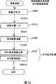
图18是表示可以应用图象数据处理装置的图象数据输出系统的一个示例的说明图。Fig. 18 is an explanatory diagram showing an example of an image data output system to which the image data processing device can be applied.
图19是表示省略颜色空间变换处理时的图象处理程序的流程图。Fig. 19 is a flowchart showing an image processing program when color space conversion processing is omitted.
图20是表示根据图象生成信息进行图象处理的处理程序的其它示例的流程图。Fig. 20 is a flowchart showing another example of a processing program for image processing based on image generation information.
图21是表示根据图象生成信息进行图象处理的处理程序的其它示例的流程图。Fig. 21 is a flowchart showing another example of a processing program for image processing based on image generation information.
具体实施方式Detailed ways
下面,按照下述顺序,根据实施示例,讲述本发明的实施方式。Next, in the following order, the embodiments of the present invention will be described based on the implementation examples.
A、图象数据输出系统的结构A. Structure of image data output system
B、图象文件的结构B. The structure of the image file
C、图象数据输出装置的结构C. The structure of the image data output device
D、数码相机中的图象处理D. Image processing in digital cameras
E、打印机中的图象处理E. Image processing in the printer
F、锐度调整处理的实施示例F. Implementation example of sharpness adjustment processing
G、自动图象质量处理的实施示例G. Implementation example of automatic image quality processing
H、使用图象数据处理装置的图象数据输出系统H. Image data output system using image data processing device
I、变形示例I. Deformation example
A、图象数据输出系统的结构:A. The structure of the image data output system:
图1是表示可以采用作为本发明的一种实施示例的输出装置的图象数据输出系统的一个示例的说明图。图象数据输出系统10,包括:作为生成图象文件的图象数据生成装置的数码相机12,和作为输出装置的打印机20。在数码相机12中生成的图象文件,通过电缆CV、或者将存放图象文件的存储卡MC直接插入打印机20,从而送给打印机20。打印机20实施根据读到的图象文件的图象数据的图象质量调整,输出图象。作为输出装置,除打印机20外,还可以使用CRT显示器、LCD显示器等的监视器14、投影仪等。下面,将具有图象调整部和图象输出部的打印机20作为输出装置,根据将存储卡MC直接插入打印机20的情况进行讲述。FIG. 1 is an explanatory diagram showing an example of an image data output system to which an output device as an example of implementation of the present invention can be used. The image
图2是表示数码相机12的简要结构的方框图。本实施示例的数码相机12,包括:收集光信息的光学电路121,控制光学电路、取得图象的图象取得电路122,加工处理取得的数字图象的图象处理电路123,控制各电路的控制电路124。控制电路124,具有图中未示出的存储器。光学电路121,包括:收集光信息的透镜125,调节光量的光圈129,将透过透镜的信息变换成图象数据的CCD128。FIG. 2 is a block diagram showing a schematic configuration of the
数码相机12,将取得的图象,保存在存储卡MC中。作为数码相机12的图象数据的保存形式,通常使用JPEG形式,但除此之外,还可以使用TIFF形式、GIF形式、BMP形式、RAW形式等保存形式。The
数码相机12,还具有:设定各种摄影条件(光圈值、快门速度、曝光调整方式、摄影方式等)的选择·决定按纽126,液晶显示器127。液晶显示器127,在预展摄影图象或使用选择·决定按纽126设定光圈值时利用。光圈值,可以按照数码相机12的种类,设定预先决定的所定范围内的值,例如从2到16之间的所定的不连续的值(例如:2、2.8、4、5.6…等)。此外,作为光圈值,通常使用F值。所以,光圈值越大,光圈越小。快门速度也可以设定所定范围内的值,例如可以设定从1/15秒~1/25秒之间的值。作为曝光调整方式,可以从程序自动(自动调整方式)、光圈优先方式、快门速度优先方式、手动方式等预先准备的多种方式中选择1个。设定为程序自动时,光圈值和快门速度被自动调整成标准值,从而使曝光设定成标准值。设定为手动方式时,使用用户设定的光圈值和快门速度。在光圈值和快门速度由用户设定的时,可以采用自动选择使用该设定值的曝光调整方式的结构。作为摄影方式,可以按照被拍摄景物的种类,从标准方式、人物方式(肖像方式)、风景方式、夜景方式等预先准备的多种方式中选择一个。由用户指定摄影方式时,按照指定的摄影方式,相关的参数(例如光圈值、透镜焦距等)就被自动设定。例如,作为摄影方式,选择标准方式时,不仅光圈值,而且与图象数据生成相关的参数,均被设定成标准值。光圈值被设定成标准值的标准摄影条件(例如,由作为曝光调整方式的程序自动决定的摄影条件,以及由作为摄影方式的标准摄影方式决定的摄影条件),是数码相机12中的默认的摄影条件。另外,标准摄影条件,常常被作为数码相机12购入时的设定而利用。The
在数码相机12中进行摄影时,图象数据和图象生成信息,被作为图象文件存放于存储卡MC中。图象生成信息,可以包含摄影时(图象数据生成时)的光圈值等参数的设定值(详细内容后文再述)。When shooting with the
B、图象文件的构成:B. Composition of image files:
图3是概念性地表示能在本实施示例中使用的图象文件的内部结构的一个例子的说明图。图象文件GF,具有存放图象数据GD的图象数据存放区101,和存放图象生成信息GI的图象生成信息存放区102。图象数据GD,例如,用JPEG形式存放;图象生成信息GI,例如,用TIFF形式(用标识符特定数据及数据区的形式)存放。此外,本实施示例中的“文件的结构”“数据的结构”这种术语,是指文件或数据等在被存放在存储装置里的状态中的文件或数据的结构。FIG. 3 is an explanatory diagram conceptually showing an example of the internal structure of an image file that can be used in this embodiment example. The image file GF has an image data storage area 101 for storing image data GD, and an image generation information storage area 102 for storing image generation information GI. The image data GD is stored in, for example, JPEG format, and the image generation information GI is stored in, for example, TIFF format (a format in which data and data areas are identified by identifiers). In addition, terms such as "file structure" and "data structure" in this example of implementation refer to the file or data structure in the state of being stored in a storage device, such as a file or data.
图象生成信息GI,是与数码相机12等图象数据生成装置中生成图象数据时(摄影时)的图象相关信息,包括以下设定值:The image generation information GI is image-related information when image data is generated (when photographing) in image data generating devices such as the
·光圈值。· Aperture value.
·快门速度。·Shutter speed.
·曝光时间。• Exposure time.
·透镜焦距。• Lens focal length.
·曝光调整方式。·Exposure adjustment method.
·摄影方式。·Photography method.
·厂家名称。·Manufacturer's name.
·型号名称。·Model Name.
·伽马值。• Gamma value.
本实施示例中的图象文件GF,一般来说具有所述的图象数据存放区101和图象生成信息存放区102就行,可以采用符合已经标准化的文件形式的文件结构。下面,具体讲述将本实施示例涉及的图象文件GF应用于Exif文件形式的情况。Generally speaking, the image file GF in this implementation example only needs to have the above-mentioned image data storage area 101 and image generation information storage area 102, and can adopt a file structure conforming to a standardized file format. Next, the case where the image file GF related to this embodiment example is applied to the Exif file format will be specifically described.
Exif文件,具有符合数码相机用图象文件格式标准(Exif)的文件结构,其规格由日本电子信息技术产业协会(JEITA)制定。另外,Exif文件形式,与图3所示概念图一样,包括:存放JPEG形式的图象数据的JPEG图象数据存放区,存放与JPEG图象数据相关的各种信息的附属信息存放区。JPEG图象数据存放区,相当于图3中的图象数据存放区101;附属信息存放区,相当于图象生成信息存放区102。附属信息存放区,存放着摄影日期、光圈值、快门速度之类有关JPEG图象的图象生成信息。The Exif file has a file structure conforming to the image file format standard (Exif) for digital cameras, and its specification is established by the Japan Electronics and Information Technology Industries Association (JEITA). In addition, the Exif file format, like the conceptual diagram shown in FIG. 3, includes: a JPEG image data storage area for storing image data in JPEG format, and an auxiliary information storage area for storing various information related to JPEG image data. The JPEG image data storage area is equivalent to the image data storage area 101 in FIG. 3 ; the auxiliary information storage area is equivalent to the image generation information storage area 102 . The auxiliary information storage area stores image generation information related to JPEG images such as shooting date, aperture value, and shutter speed.
图4是讲述附属信息存放区103的数据结构例的说明图。为了特定数据区域,在Exif文件形式中使用着层次性的标识符。各数据区域,可以在其内部包含由下位的标识符特定的多个下位数据区域。在图4中,用四边形包围的区域,表示一个数据区域,标识符名称写在其左上角。在该实施示例中,包含标识符名称为APP0、APP1、APP6等3个数据区域。APP1数据区域,在其内部包含标识符名称为IFD0、IFD1等2个数据区域。IFD0数据区域,在其内部包含标识符名称为PM、Exif、GPS等3个数据区域。数据及数据区域,被按照规定的地址或偏置值存放,地址或偏置值可以利用标识符名称进行检索。在输出装置一侧,可以通过指定与所需的信息对应的地址或偏置值,取得与所需的信息对应的数据。FIG. 4 is an explanatory diagram showing an example of the data structure of the subsidiary
图5是讲述可以在图4中按照APP1-IFD0-Exif的顺序参照标识符名称的Exif数据区域的数据结构(数据的标识符名称和参数值)的一个例子的说明图。Exif数据区域,如图4所示,可以包含标识符名称为MakerNote的数据区域;MakerNote的数据区域,进而还能包含多个数据区域,但在图5中没有示出。FIG. 5 is an explanatory diagram showing an example of the data structure (identifier name and parameter value of data) of the Exif data area that can refer to the identifier name in the order of APP1-IFD0-Exif in FIG. 4 . The Exif data area, as shown in FIG. 4 , can include a data area whose identifier name is MakerNote; the data area of MakerNote can further include multiple data areas, but it is not shown in FIG. 5 .
Exif数据区域,如图5所示,存入与曝光时间、光圈值、曝光程序、透镜焦距、摄影情景类型等信息对应的参数值。光圈值,可以作为光圈信息使用,进而,曝光程序和摄影情景,可以作为动作方式信息使用。The Exif data area, as shown in Figure 5, stores parameter values corresponding to information such as exposure time, aperture value, exposure program, lens focal length, and photography scene type. The aperture value can be used as aperture information, and the exposure program and shooting scene can be used as operation mode information.
曝光程序是识别曝光调整方式的信息,从例如包含下述4个值的多个值中选择、设定。The exposure program is information for identifying an exposure adjustment method, and is selected and set from a plurality of values including, for example, the following four values.
参数值1:手动方式。Parameter value 1: manual mode.
参数值2:程序自动。Parameter value 2: the program is automatic.
参数值3:光圈优先方式。Parameter value 3: Aperture priority mode.
参数值4:快门速度方式。Parameter value 4: Shutter speed mode.
摄影情景类型是识别摄影方式的信息,从例如标准方式、人物方式(肖像方式)、风景方式、夜景方式中选择、设定。The shooting scene type is information for identifying a shooting mode, and is selected and set from, for example, a standard mode, a portrait mode (portrait mode), a landscape mode, and a night view mode.
与图象数据相关的信息,还可以适当存放在图4中的Exif数据区域以外的区域。例如:作为特定图象数据生成装置的厂家名称及型号名称,存放在标识符名称是IFDO的数据区域。Information related to image data can also be appropriately stored in an area other than the Exif data area in FIG. 4 . For example, the manufacturer name and model name of the specific image data generating device are stored in the data area whose identifier name is IFDO.
C、图象数据输出装置和结构:C, image data output device and structure:
图6是表示本实施示例的打印机20的简要结构的方框图。打印机20,是可以输出图象的打印机,例如是将蓝绿(C)、洋红(Mg)、黄(Y)、黑(K)四种颜色的墨水喷到印刷媒体上、形成圆点图案的喷墨式打印机。另外,还可以使用将调色剂(toner)在印刷媒体上复制、定影后形成图象的电子照片方式的打印机。在墨水中,除了上述4色外,还可以使用比蓝绿(C)淡的淡蓝绿(LC),比洋红(Mg)淡的淡洋红(LM)、比黄(Y)浓的深黄(DY)。另外,进行单色打印时,既可以采用只使用黑色(K)的结构,也可以采用使用红(R)及绿(G)的结构。使用的墨水及调色剂的种类,可以根据输出图象的特点决定。FIG. 6 is a block diagram showing a schematic configuration of the
打印机20,如图所示,包括:驱动搭载在托架21上的打印头211喷出墨水及形成圆点的机构、在托架电机22的作用下使托架21沿着压纸卷筒23的轴向往复运动的机构、以及在送纸电机24的作用下运送打印纸P的机构和控制电路30。利用这些机构,打印机20发挥着图象输出部的功能。使托架21沿着压纸卷筒23的轴向往复运动的机构,由可以滑动地保持与压纸卷筒23的轴平行架设的托架21的滑动轴25、在与托架电机22之间安装无头的驱动皮带26的皮带轮27、以及检测托架21的原点位置的位置检测传感器28等构成。运送打印纸P的机构,由压纸卷筒23、传压纸卷筒23旋转的送纸电机24、图中未示出的给纸辅助滚轮和将送纸电机24的旋转力传递给压纸卷筒23及给纸辅助滚轮的齿轮系(图中未示出)构成。
控制电路30,与打印机操作盘29交换信息,适当控制送纸电机24及托架电机22、打印头211的动作。向打印机20供给的打印纸P,设置在压纸卷筒23和送纸辅助滚轮之间,按照压纸卷筒23的转动角度,供送相应的所定量。The control circuit 30 exchanges information with the printer operation panel 29, and appropriately controls the actions of the paper feeding motor 24, the carriage motor 22, and the print head 211. The printing paper P supplied to the
托架21,具有打印头211,另外还搭载着可以利用的墨水的墨水盒。在打印头211的下面,设置着喷出可以利用的墨水的喷咀(图中未示出)。The carriage 21 has a print head 211 and also carries an ink tank for usable ink. Below the print head 211, nozzles (not shown) for ejecting available ink are provided.
图7是表示以打印机20的控制电路30为中心的打印机20的结构的方框图。在控制电路30的内部,设置着CPU31、PROM32、RAM33、从存储卡MC取得数据的存储卡插槽34、与送纸电机24及托架电机22等进行数据交换的外围机器输出入部(PIO)35和驱动缓冲器37等。驱动缓冲器37,作为向打印头211供给圆点(dot)的ON·OFF信号的缓冲器使用。它们彼此用总线38连接,可以互换数据。另外,在控制电路30中,还设置着用所定的频率输出驱动波形的发信器39,和按照所定的时序将来自发信器39的输出分配给打印头211的分配输出器40。FIG. 7 is a block diagram showing the configuration of the
另外,控制电路30,一边与送纸电机24及托架电机22的动作同步,一边按照所定的时序将圆点数据向驱动缓冲器37输出。进而,控制电路30从存储卡MC读出图象文件,解析附属信息,根据得到的图象生成信息进行图象处理。就是说,控制电路30发挥着图象质量调整部的功能。由控制电路30实施的详细的图象处理流程,我们后文再述。In addition, the control circuit 30 outputs dot data to the drive buffer 37 at predetermined timing while synchronizing with the operation of the paper feed motor 24 and the carriage motor 22 . Furthermore, the control circuit 30 reads the image file from the memory card MC, analyzes the attached information, and performs image processing based on the obtained image generation information. That is, the control circuit 30 functions as an image quality adjustment unit. The detailed image processing flow implemented by the control circuit 30 will be described later.
D、数码相机中的图象处理:D. Image processing in digital cameras:
图8是表示数码相机12中的图象文件GF的生成处理流程的流程图。FIG. 8 is a flowchart showing the flow of the generation process of the image file GF in the
数码相机12的控制电路124(图2),按照摄影要求——例如按下快门后——生成图象数据GD(步骤S100)。在光圈值、曝光调整方式、摄影方式等参数值被设定时,生成使用设定的参数值的图象数据GD。The control circuit 124 (FIG. 2) of the
控制电路124,将生成的图象数据GD和图象生成信息GI,作为图象文件GF,存入存储卡MC(步骤S110),结束本处理程序。图象生成信息GI,包括:光圈值、快门速度等图象生成时使用的参数值,曝光调整方式、摄影方式等可以任意设定的参数值,厂家名称、型号名称等被自动设定的参数值。另外,图象数据GD,在由RGB颜色空间变换成YCbCr颜色空间后,经JPEG压缩,作为图象文件GF存放。The control circuit 124 stores the generated image data GD and image generation information GI in the memory card MC as an image file GF (step S110), and ends this processing routine. Image generation information GI includes: parameter values used in image generation such as aperture value and shutter speed, parameter values that can be set arbitrarily, such as exposure adjustment method and shooting method, and parameters that are automatically set such as manufacturer name and model name value. In addition, the image data GD is converted from the RGB color space to the YCbCr color space, compressed by JPEG, and stored as an image file GF.
在数码相机12中实施以上处理后,存入存储卡MC中的图象文件GF,便在设定图象数据GD的同时,还设定包含图象数据生成时的各参数值的图象生成信息GI。After the above processing is carried out in the
E、打印机中的图象处理:E. Image processing in the printer:
图9是表示本实施示例的打印机20中图象处理的处理程序的流程图。在以下的讲述中,对根据将存放图象文件GF的存储卡MC直接插入打印机20的情况进行讲述。将存储卡MC插入存储卡插槽34后,打印机20的控制电路30(图7)的CPU31就从存储卡MC存储卡MC读出图象文件GF(图3)(步骤S200)。接着,在步骤S210中,CPU31从图象文件GF的附属信息存放区,检索表示图象数据生成时的信息的图象生成信息GI。在能够发现图象生成信息GI时(步骤S220:Y),CPU31取得并解析图象生成信息GI(步骤S230)。CPU31,根据解析的图象生成信息GI,实施后叙的图象处理(步骤S240),输出处理的图象(步骤S250),结束本处理程序。FIG. 9 is a flowchart showing a processing procedure for image processing in the
另一方面,在使用图样应用程序等生成的图象文件中,不包含具有光圈值等信息的图象生成信息GI。CPU31在不能够发现图象生成信息GI时(步骤S220:N),实施标准处理(步骤S260),输出处理的图象(步骤S250),结束本处理程序。On the other hand, image generation information GI having information such as an aperture value is not included in an image file generated using a graphic application program or the like. When the image generation information GI cannot be found (step S220: N), the CPU 31 performs standard processing (step S260), outputs the processed image (step S250), and ends this processing routine.
图10是表示根据图象生成信息进行的图象处理(相当于图9中的步骤S240)的处理程序的流程图。打印机20的控制电路30(图7)的CPU31,从读出图象文件GF取出图象数据GD(步骤S300)。FIG. 10 is a flowchart showing a processing procedure of image processing (corresponding to step S240 in FIG. 9 ) performed based on image generation information. The CPU 31 of the control circuit 30 (FIG. 7) of the
数码相机12,如上所述,将图象数据GD作为JPEG形式的文件保存,在JPEG形式的文件中,使用YCbCr颜色空间保存图象数据。CPU31在步骤S310中,为了将根据YCbCr颜色空间的图象数据变换成根据RGB颜色空间的图象数据,实施使用3×3矩阵S的运算。该矩阵运算,例如是如下所示的运算式。As described above, the
数码相机12生成的图象数据的颜色空间,比所定的颜色空间例如sRGB颜色空间大时,根据在步骤S310中获得的RGB颜色空间的图象数据,有时在该RGB颜色空间的定义域外,包含有效数据。在图象生成信息GI中,指定将这些定义域外的数据作为有效数据处理时,就将定义域外的数据照原样保存,继续以后的图象处理。没有指定将定义域外的数据作为有效数据处理时,则将定义域外的数据剪辑成定义域内。例如:定义域是0~255时,将不足0的负值的数据,限制为0;将256以上的数据限制为255。图象输出部的可以表现的颜色空间,比所定的颜色空间例如sRGB颜色空间大时,尽管在图象生成信息GI中指定,但最好剪辑成定义域内。这种情况,例如,有时可以表现的颜色空间向是sRGB颜色空间的CRT输出。When the color space of the image data generated by the
接着,在步骤S320中,CPU31进行伽马校正及使用矩阵M的运算,将根据RGB颜色空间的图象数据变换成根据XYZ颜色空间的图象数据。图象文件GF,可以包含图象生成时的伽马值和颜色空间信息。在图象生成信息GI包含这些信息时,CPU31从图象生成信息GI中取得图象数据的伽马值,使用取得的伽马值实施图象数据的灰度系数变换处理。进而,CPU31从图象生成信息GI中取得图象数据的颜色空间信息,使用与该颜色空间对应的矩阵M,实施图象数据的矩阵运算。在图象生成信息GI不包含伽马值时,可以使用标准的伽马值,实施灰度系数变换处理。另外,在图象生成信息GI不包含颜色空间信息时,可以使用标准的矩阵M,实施图象数据的矩阵运算。作为这些标准的伽马值以及矩阵M,例如可以使用对sRGB颜色空间而言的伽马值和矩阵。该矩阵运算,例如是如下所示的运算式。Next, in step S320, the CPU 31 performs gamma correction and calculation using the matrix M to convert the image data based on the RGB color space into image data based on the XYZ color space. The image file GF can contain gamma value and color space information when the image is generated. When the image generation information GI includes these information, the CPU 31 obtains the gamma value of the image data from the image generation information GI, and performs gamma conversion processing of the image data using the obtained gamma value. Further, the CPU 31 obtains the color space information of the image data from the image generation information GI, and performs matrix operation on the image data using the matrix M corresponding to the color space. When the image generation information GI does not include a gamma value, a standard gamma value can be used to perform gamma conversion processing. In addition, when the image generation information GI does not include color space information, a standard matrix M can be used to perform matrix operations on image data. As these standard gamma values and matrix M, for example, gamma values and matrices for the sRGB color space can be used. This matrix calculation is, for example, the following calculation formula.
Rt,Gt,Bt≥0Rt, Gt, Bt≥0
Rt,Gt,Bt<0Rt, Gt, Bt<0
实施矩阵运算后得到的图象数据的颜色空间,是XYZ颜色空间。XYZ颜色空间是绝对颜色空间,是不依赖数码相机及打印机这类装置的装置非依赖性颜色空间。因此,可以通过XYZ颜色空间进行颜色空间的变换,从而进行不依赖装置的彩色协调。The color space of the image data obtained after performing the matrix operation is the XYZ color space. The XYZ color space is an absolute color space, and is a device-independent color space that does not depend on devices such as digital cameras and printers. Therefore, it is possible to convert the color space from the XYZ color space, thereby performing color coordination independent of the device.
接着,在步骤S330中,CPU31进行使用矩阵N-1的运算及反伽马校正,将根据XYZ颜色空间的图象数据变换成根据wRGB颜色空间的图象数据。在进行反伽马校正之际,CPU31从PROM32中取得打印机的伽马值,使用取得的伽马值的倒数,实施图象数据的灰度系数变换处理。进而,CPU31从PROM32中取得与由XYZ颜色空间向wRGB颜色空间变换对应的矩阵N-1,使用该矩阵N-1实施图象数据的矩阵运算。该矩阵运算,例如是如下所示的运算式。Next, in step S330, the CPU 31 performs calculations using the matrix N -1 and inverse gamma correction to convert the image data based on the XYZ color space into image data based on the wRGB color space. When inverse gamma correction is performed, the CPU 31 acquires the gamma value of the printer from the PROM 32, and performs gamma conversion processing of the image data using the reciprocal of the acquired gamma value. Further, the CPU 31 acquires a matrix N -1 corresponding to the conversion from the XYZ color space to the wRGB color space from the PROM 32 , and performs matrix operations on image data using the matrix N -1 . This matrix calculation is, for example, the following calculation formula.
接着,在步骤S340中,CPU31进行图象质量的自动调整处理。在本实施示例中的自动图象质量调整处理,使用图象文件GF包含的图象生成信息,特别是作为光圈信息的光圈值,和作为动作方式信息的曝光程序的参数值,实施调整图象数据的锐度的自动图象质量调整处理。关于锐度调整和自动图象质量调整处理,我们后文再述。Next, in step S340, the CPU 31 performs automatic image quality adjustment processing. In the automatic image quality adjustment process in this implementation example, the image generation information contained in the image file GF, especially the aperture value as the aperture information, and the parameter value of the exposure program as the operation mode information are used to adjust the image. Automatic image quality adjustment processing of data sharpness. About sharpness adjustment and automatic image quality adjustment processing, we will discuss later.
接着,在步骤S350中,CPU31进行旨在打印的CMYK颜色变换处理及中间色调处理。在CMYK颜色变换处理中,CPU31参照存放在PROM32内的由wRGB颜色空间向CMYK颜色空间变换用对照表(LUT),将图象数据的颜色空间由wRGB颜色空间向CMYK颜色空间变更。就是说,将由RGB的阶梯值构成的图象数据,变换成在打印机20中使用的例如由C(Cyan)Mg(Magenta)Y(Yellow)K(Black)LC(Light Cyan)LM(LightMagenta)等6种颜色的阶梯值构成的图象数据。Next, in step S350, the CPU 31 performs CMYK color conversion processing and halftone processing for printing. In the CMYK color conversion process, the CPU 31 refers to a wRGB color space to CMYK color space conversion look-up table (LUT) stored in the PROM 32 to change the color space of the image data from the wRGB color space to the CMYK color space. That is to say, the image data composed of RGB gradation values is converted into, for example, C (Cyan) Mg (Magenta) Y (Yellow) K (Black) LC (Light Cyan) LM (Light Magenta) etc. used in the
在中间色调处理中,CPU31实施所谓的“中间色调处理”,由经过颜色变换的图象数据,生成中间色调图象数据。该中间色调图象数据,按照应该向驱动缓冲器37(图7)发送的顺序改变排列,成为最终的打印数据,结束本处理程序。由本处理程序处理的图象数据,在图9所示的图象处理程序的步骤S250中被输出。In halftone processing, the CPU 31 executes so-called "halftone processing" to generate halftone image data from image data subjected to color conversion. The halftone image data is arranged in a different order in order to be sent to the drive buffer 37 (FIG. 7) to become the final print data, and this processing routine ends. The image data processed by this processing program is output in step S250 of the image processing program shown in FIG. 9 .
F、锐度调整处理的实施示例:F. Example of implementation of sharpness adjustment processing:
锐度调整,可以使用非锐屏蔽(unsharp mask)的方法。图11是讲述使用非锐屏蔽的锐度调整方法的示意图。使用在直线上排列的象素的亮度值,阶段性地讲述锐度调整。For sharpness adjustment, you can use the method of unsharp mask. FIG. 11 is a diagram illustrating a sharpness adjustment method using an unsharp mask. Sharpness adjustment is described step by step using the luminance values of pixels arranged on a straight line.
图11(a)示出进行锐度调整之前的原数据ODATA。纵横表示各象素的锐度值,在该例中,可以取从0~100之间的值。横轴表示象素的位置,一个标志点表示直线上排列的多个象素内的一个象素。就是说,表示直线上排列的象素的标志点,按照象素的排列顺序,沿着横轴排列。这样,将亮度值阶段状变化的区域的数据,作为原数据ODATA使用,讲述锐度调整。Fig. 11(a) shows the original data ODATA before sharpness adjustment. Vertical and horizontal represent the sharpness value of each pixel, and in this example, values between 0 and 100 can be taken. The horizontal axis represents the position of the pixel, and one marker point represents one pixel among a plurality of pixels arranged on a straight line. That is to say, marker points representing pixels arranged on a straight line are arranged along the horizontal axis in accordance with the arrangement order of the pixels. In this way, sharpness adjustment will be described using the data of the region where the luminance value changes stepwise as original data ODATA.
为了加强锐度,可以采用使用非锐屏蔽的方法。该方法是先准备锐度变化迟钝(非锐)的数据,再从原数据减去非锐数据,从而使锐度变化敏锐起来的方法。非锐数据,可以使用其周围的象素的亮度值,将原数据的各象素的亮度值平均化后得到。作为平均化的方法,可以采用将对象象素的亮度值及其周围的象素的亮度值加在一起,求出它们的平均值的方法。另外,还可以采取使用比比较近(象素间的距离短)的象素的亮度值大的加权数,求出平均值的方法。作为这种加权函数(非锐屏蔽),可以使用以对象象素为中心的高斯函数(因为实际的图象数据的象素是二维配置,所以使用二维高斯函数)。In order to enhance the sharpness, the method of using unsharp masking can be adopted. This method is a method of first preparing data with slow (non-sharp) changes in sharpness, and then subtracting the non-sharp data from the original data to sharpen the change in sharpness. Unsharp data can be obtained by averaging the brightness values of pixels in the original data using the brightness values of surrounding pixels. As a method of averaging, a method of adding the luminance value of the target pixel and the luminance values of surrounding pixels to obtain their average value can be used. Alternatively, a method may be employed in which an average value is obtained using a weighting number greater than that of the luminance values of relatively close (shorter distance between pixels) pixels. As such a weighting function (non-sharp mask), a Gaussian function centered on the target pixel can be used (a two-dimensional Gaussian function is used because the pixels of the actual image data are two-dimensionally arranged).
图11(b)示出使用非锐屏蔽生成的非锐数据UDATA的亮度值。与原数据ODATA相比,可知亮度值的变化变得和缓了。Fig. 11(b) shows the luminance value of the unsharp data UDATA generated using the unsharp mask. Compared with the original data ODATA, it can be seen that the change of the luminance value becomes gentler.
图11(c)是从原数据ODATA减去非锐数据UDATA后的差值数据DIFF。将所定的系数乘以该差值数据DIFF后的积,与原数据ODATA相加后,可得到使亮度值的变化敏锐的鲜明数据。图11(d)示出分别用不同的系数G后得到的鲜明数据的亮度值。S1表示用比较小的系数G1后得到的鲜明数据,S2表示用比较大的系数G2后得到的鲜明数据。S1、S2的亮度值的变化,都比原数据急剧,图象的锐度增强。另外,比较S1和S2后可知:系数G越大,越能将锐度调强。将系数G设定为0后,鲜明数据与原数据ODATA相等,不进行锐度调整。Fig. 11(c) is difference data DIFF after subtracting unsharp data UDATA from original data ODATA. By multiplying the product of the difference data DIFF by a predetermined coefficient and adding it to the original data ODATA, clear data that sharply changes the brightness value can be obtained. FIG. 11( d ) shows brightness values of sharp data obtained by using different coefficients G respectively. S1 represents clear data obtained by using a relatively small coefficient G1, and S2 represents clear data obtained by using a relatively large coefficient G2. The changes of the luminance values of S1 and S2 are sharper than the original data, and the sharpness of the image is enhanced. In addition, after comparing S1 and S2, it can be seen that the larger the coefficient G is, the stronger the sharpness can be adjusted. After the coefficient G is set to 0, the sharpness data is equal to the original data ODATA, and no sharpness adjustment is performed.
作为将锐度调弱的方法,可以使用将上述的非锐数据UDATA作为调整后的数据的方法。这时,加大非锐屏蔽的宽度,可以得到亮度值的变化比较迟钝的非锐数据。As a method of reducing the sharpness, a method of using the above-mentioned unsharp data UDATA as adjusted data can be used. At this time, increasing the width of the non-sharp mask can obtain non-sharp data whose luminance value changes slowly.
这样,调整系数G及非锐屏蔽的宽度,可以改变锐度调整的程度。In this way, adjusting the coefficient G and the width of the unsharp mask can change the degree of sharpness adjustment.
G、自动图象质量调整处理的实施示例:G. Implementation example of automatic image quality adjustment processing:
G1、自动图象质量调整处理的第1实施示例:The first implementation example of G1, automatic image quality adjustment processing:
图12是本实施示例中的自动图象质量调整处理(相当于图10中的步骤S340)的处理程序的流程图。CPU31(图7),解析图象生成信息G1,取得光圈值及曝光程序的参数值(步骤S400)。接着,在步骤S410中,判断图象数据生成时的光圈值是不是手动设定。在该实施例中,作为手动设定,可以选择手动的曝光调整方式和光圈优先的曝光调整方式。手动方式时,曝光程序(图5)的值是1;光圈优先方式时,是3。CPU31判断曝光程序的值是1还是3。FIG. 12 is a flowchart of the processing procedure of the automatic image quality adjustment processing (corresponding to step S340 in FIG. 10 ) in this embodiment example. The CPU 31 (FIG. 7) analyzes the image generation information G1 to obtain the aperture value and the parameter value of the exposure program (step S400). Next, in step S410, it is judged whether the aperture value when the image data is generated is manually set. In this embodiment, as the manual setting, a manual exposure adjustment method and an aperture priority exposure adjustment method can be selected. In the manual mode, the value of the exposure program (Figure 5) is 1; in the aperture priority mode, it is 3. The CPU 31 judges whether the value of the exposure program is 1 or 3.
在断定曝光调整方式既不是手动方式又不是光圈优先方式时(步骤S410:N),在步骤S430中,CPU31进行锐度调整的程度是标准的图象质量调整。在断定曝光调整方式不是手动方式或是光圈优先方式时(步骤S410:Y),由于光圈值是手动设定,所以可以断定用户试图将图象的景深设定成最理想的水平。这时,CPU31在步骤S420中,在光圈小(光圈值大)时实施锐度调整的程度强的图象质量调整。When it is determined that the exposure adjustment mode is neither manual mode nor aperture priority mode (step S410: N), in step S430, the degree of sharpness adjustment performed by CPU 31 is standard image quality adjustment. When it is determined that the exposure adjustment mode is not the manual mode or the aperture priority mode (step S410: Y), since the aperture value is manually set, it can be concluded that the user is trying to set the depth of field of the image to an optimal level. At this time, in step S420, the CPU 31 executes image quality adjustment with a strong degree of sharpness adjustment when the aperture is small (large aperture value).
图13是表示锐度调整的程度与光圈值的关系示例的说明图。纵轴表示锐度调整的程度(以下称作“锐度强度”),其值愈大,就意味着锐度愈被强调。横轴表示光圈值F。STD表示在数码相机12的标准摄影条件下设定光圈值时图象质量调整的锐度强度(以下称作“标准锐度强度”),;C1表示光圈值为手动设定时图象质量调整的锐度强度(以下称作“高锐度强度”)。在该实施示例中,标准锐度强度STD,在曝光调整方式是程序自动和快门速度优先方式中的某一个时(图12的步骤S430)使用。此外,所谓“数码相机12的标准摄影条件”,是指数码相机12出厂时的默认的摄影条件。通常相当于程序自动形成的摄影条件。在快门速度优先方式时,也可以采用与标准锐度强度STD不同的锐度强度进行图象质量调整的结构。13 is an explanatory diagram showing an example of the relationship between the degree of sharpness adjustment and the aperture value. The vertical axis represents the degree of sharpness adjustment (hereinafter referred to as "sharpness intensity"), and a larger value means that the sharpness is emphasized more. The horizontal axis represents the aperture value F. STD represents the sharpness intensity of the image quality adjustment (hereinafter referred to as "standard sharpness intensity") when the aperture value is set under the standard shooting condition of the
高锐度强度C1,在光圈值为8以上时,成为大于标准锐度强度STD的结构。这样一来,在用户希望更加鲜明的图象输出而将光圈值设定成比较大的值(缩小光圈)时,可以有效地输出鲜明的图象。使高锐度强度C1大于标准锐度强度STD的光圈值的所定值,不限于8,可以设定为任意值,例如:设定为4,可以输出更加鲜明的图象;设定为11,可以输出更加柔和的图象。The high sharpness intensity C1 has a structure larger than the standard sharpness intensity STD when the aperture value is 8 or more. In this way, when the user wants to output a clearer image and sets the aperture value to a relatively large value (stops down the aperture), a clearer image can be effectively output. Make the high sharpness intensity C1 greater than the set value of the aperture value of the standard sharpness intensity STD, not limited to 8, can be set to any value, for example: set to 4, can output a more vivid image; set to 11, A softer image can be output.
作为标准锐度强度STD,可以使用预先的值,以便使数码相机12在标准条件(例如程序自动)下生成的图象的输出结果成为最佳。也可以解析每个图象的图象锐度,根据解析结果,调整标准锐度强度STD,以便使图象的锐度接近锐度的基准值。图象的锐度,例如,可以将1个象素和周围的所定的象素的亮度差的绝对值,定义为1个象素的边缘量,通过求出所有的象素的边缘量的平均值后获得。另外,也可以将边缘量大的象素(即可以认为相当于图象中的边缘的象素)的加权值加大后求出的平均值定义为锐度。此外,还可以将不进行锐度调整作为标准锐度强度STD设定。这样,即使通过各种方法设定标准锐度强度STD时,在将光圈值设定在所定范围中时(在本实施示例中,光圈值是8以上时),高锐度强度C1仍大于设定的标准锐度强度STD。As the standard sharpness intensity STD, a predetermined value may be used in order to optimize the output result of an image generated by the
手动设定的图象质量调整的高锐度强度C1,可以根据图象的锐度的定量评价及输出结果的感觉评价,比较进行了锐度强的图象质量调整的图象数据和对相同的原来的图象进行了锐度标准的图象质量调整的图象数据之后决定,以便使图象的输出结果成为最佳状态。例如,对于相同的图象数据,可以将曝光程序的参数值设定为3(光圈优先方式)后的输出结果,和将曝光程序的参数值设定为2(程序自动)后的输出结果,进行比较之后决定。不限于光圈值及曝光,在图象数据生成装置中可以利用将图象生成时的各种参数值自动调整成标准值的动作方式时,可以通过对用该动作方式设定的输出结果和相同的原来的图象数据的用光圈优先方式设定的输出结果进行比较,调查锐度调整强度的高低。另外,在该实施示例中,在曝光调整方式是手动方式和光圈优先方式时,进行使用相同的锐度强度的图形质量调整,但也可以根据曝光调整方式,分别进行锐度强度不同的图形质量调整。The manually set high sharpness intensity C1 of image quality adjustment can compare the image data with strong sharpness adjustment and the same The original image is determined after performing the image data of the image quality adjustment of the sharpness standard so that the output result of the image becomes the best state. For example, for the same image data, the output result after setting the parameter value of the exposure program to 3 (aperture priority mode), and the output result after setting the parameter value of the exposure program to 2 (program automatic), Decide after comparing. Not limited to the aperture value and exposure, when the image data generation device can use the action mode that automatically adjusts various parameter values at the time of image generation to the standard value, the output result set by the action mode can be set with the same Compare the output results of the original image data with the aperture priority setting to investigate the level of sharpness adjustment. In addition, in this embodiment example, when the exposure adjustment method is the manual method and the aperture priority method, the image quality adjustment using the same sharpness intensity is performed, but it is also possible to perform image quality adjustments with different sharpness intensities depending on the exposure adjustment method. Adjustment.
G2、自动图象质量调整处理的第2实施示例:The second implementation example of G2, automatic image quality adjustment processing:
图14是表示自动图象质量调整处理的第2实施示例中图象质量调整的锐度强度与光圈值的关系的说明图。纵轴和横轴的意义,STD和C1的意义,都与图13相同。Fig. 14 is an explanatory diagram showing the relationship between the sharpness intensity of the image quality adjustment and the aperture value in the second embodiment example of the automatic image quality adjustment process. The meanings of the vertical axis and the horizontal axis, and the meanings of STD and C1 are the same as those in Fig. 13 .
第2实施示例,与图13所示的第1实施示例不同,标准锐度强度STD,伴随着光圈值的增加而连续性地增加。这样,在进行锐度标准的图象质量调整时,也能表现光圈值造成的锐度的差异。进而,将光圈值设定为所定值(在该实施示例中为8)以上时的高锐度强度C1,大于标准锐度强度STD,可以更好地实现用户希望鲜明的图象输出的愿望。此外,标准锐度强度STD,还可以采用分作多个阶段,伴随着光圈值的增加而阶段状地增加的结构。The second implementation example differs from the first implementation example shown in FIG. 13 in that the standard sharpness intensity STD increases continuously as the aperture value increases. In this way, the difference in sharpness caused by the aperture value can also be expressed when the image quality adjustment of the sharpness standard is performed. Furthermore, when the aperture value is set above a predetermined value (8 in this example), the high sharpness intensity C1 is greater than the standard sharpness intensity STD, so that the user's desire for clear image output can be better realized. In addition, the standard sharpness level STD may be divided into a plurality of stages and increase in stages as the aperture value increases.
G3、自动图象质量调整处理的第3实施示例:G3, the 3rd implementation example of automatic image quality adjustment processing:
图15是表示自动图象质量调整处理的第3实施示例中锐度强度与光圈值的关系的说明图。第3实施示例,与图13所示的第1实施示例不同,在将光圈值设定为所定值(在该实施示例中为8)以上时,高锐度强度C1,伴随着光圈值的增加而连续性地增加。这样,可以根据光圈值,更细微地进行锐度的强调处理。此外,高锐度强度C1,还可以采用分作多个阶段,伴随着光圈值的增加而阶段状地增加的结构。Fig. 15 is an explanatory diagram showing the relationship between the sharpness intensity and the aperture value in the third embodiment example of automatic image quality adjustment processing. The third implementation example differs from the first implementation example shown in FIG. 13 in that when the aperture value is set to a predetermined value (8 in this implementation example) or more, the sharpness intensity C1 increases with the increase of the aperture value. And increase continuously. In this way, sharpness can be emphasized more finely according to the aperture value. In addition, the high sharpness intensity C1 may be divided into a plurality of stages and increase in stages as the aperture value increases.
G4、自动图象质量调整处理的第4实施示例:G4, the 4th implementation example of automatic image quality adjustment processing:
图16是表示自动图象质量调整处理的第4实施示例中锐度强度与光圈值的关系的说明图。第4实施示例,与图13所示的第1实施示例不同,在光圈值可取的全部范围内,高锐度强度C1,伴随着光圈值的增加而连续性地增加。这样,可以根据光圈值,更细微地进行锐度的强调处理。此外,高锐度强度C1,还可以采用分作多个阶段,伴随着光圈值的增加而阶段状地增加的结构。Fig. 16 is an explanatory diagram showing the relationship between the intensity of sharpness and the aperture value in the fourth embodiment of automatic image quality adjustment processing. The fourth implementation example differs from the first implementation example shown in FIG. 13 in that the high-sharpness intensity C1 continuously increases with an increase in the aperture value within the entire range of available aperture values. In this way, sharpness can be emphasized more finely according to the aperture value. In addition, the high sharpness intensity C1 may be divided into a plurality of stages and increase in stages as the aperture value increases.
G5、自动图象质量调整处理的第5实施示例:G5. The fifth implementation example of automatic image quality adjustment processing:
图17是表示自动图象质量调整处理的第5实施示例中锐度强度与光圈值的关系的说明图。在第5实施示例中,采用在光圈值是生成该图象的装置中可以利用的光圈值的最大值时,高锐度强度C1大于标准锐度强度STD的结构。例如,在图17所示的例子中,采用光圈值的最大值是11,在光圈值是11时,高锐度强度C1大于标准锐度强度STD的结构。因此,用户通过将光圈值设定为最大值这一简单操作,就能输出鲜明的图象。Fig. 17 is an explanatory diagram showing the relationship between the intensity of sharpness and the aperture value in the fifth embodiment of automatic image quality adjustment processing. In the fifth embodiment, when the aperture value is the maximum value of the aperture value available to the device for generating the image, the high sharpness intensity C1 is higher than the standard sharpness intensity STD. For example, in the example shown in FIG. 17 , the maximum value of the aperture value is 11, and when the aperture value is 11, the high sharpness intensity C1 is greater than the standard sharpness intensity STD. Therefore, the user can output sharp images with a simple operation of setting the aperture value to the maximum value.
光圈值的最大值,是按照数码相机12的种类(更一般地说,是图象数据生成装置的种类)而定的值。图象文件GF的图象生成信息G1包含光圈值的最大值时,CPU31(图7)可以取得该值,进行与光圈值对应的锐度强度的调整。或者还可以在PROM32(图7)等存储器中,存放由图象数据生成装置与光圈值的最大值组合而成的光圈值表。图象生成信息G1,作为光圈值的最大值的相关信息,例如包含厂家名称和型号名称时,CPU31可以使用厂家名称和型号名称,从光圈值表中取得光圈值的最大值。此外,光圈值表还可以通过网络等联机取得。这样,可以将光圈值表适当更新为包含最新信息的表。因此,作为光圈值的最大值的相关信息,还可以使用特定图象生成装置的种类的信息。The maximum value of the aperture value is a value determined according to the type of digital camera 12 (more generally, the type of image data generating device). When the image generation information G1 of the image file GF includes the maximum value of the aperture value, the CPU 31 (FIG. 7) can acquire this value and adjust the sharpness intensity corresponding to the aperture value. Alternatively, the aperture value table formed by the combination of the image data generating device and the maximum value of aperture values may be stored in a memory such as PROM 32 (FIG. 7). When the image generation information G1 includes, for example, a manufacturer's name and a model name as information related to the maximum value of the aperture value, the CPU 31 can use the manufacturer's name and model name to obtain the maximum value of the aperture value from the aperture value table. In addition, the aperture value table can also be obtained online through the Internet or the like. In this way, the aperture value table can be appropriately updated to a table containing the latest information. Therefore, as the information on the maximum value of the aperture value, information specifying the type of image generating device may also be used.
H、使用图象数据处理装置的输出系统的结构:H, use the structure of the output system of image data processing device:
图18是表示可以应用作为本发明的一种实施方式的图象数据处理装置的输出系统的一个示例的说明图。图象数据输出系统10B,具有:作为生成图象文件的图象数据生成装置的数码相机12,实施根据图象文件的图象质量调整处理的计算机PC,作为输出图象的图象数据输出装置的打印机20B。计算机PC,是被普遍使用的类型的计算机,作为图象数据处理装置发挥作用。作为图象数据输出装置,除了打印机20B之外,还可以使用、CRT显示器、LCD显示器等监视器14B和投影仪等。在以下的讲述中,将打印机20B作为图象数据输出装置。在本实施示例中,具有图象质量调整部的图象数据处理装置和具有图象输出部的图象数据输出装置独立构成的这一点,与上述的图象数据输出系统的实施示例(图1)不同。此外,作为图象数据处理装置的计算机PC,和具有图象输出部的打印机,可以称作广义的“输出装置”。FIG. 18 is an explanatory diagram showing an example of an output system to which an image data processing device according to an embodiment of the present invention can be applied. The image data output system 10B has: a
在数码相机20中生成的图象文件,通过电缆CV,或将存放图象文件的存储卡MC直接插入计算机PC,向计算机PC发送。计算机PC实施根据读出的图象文件的图象数据的图象质量调整处理。图象质量调整处理后生成的图象数据,通过电缆CV,发送给打印机20B,由打印机20B输出。The image files generated by the
计算机PC,具有:实施实现上述图象质量调整处理的程序的CPU150,暂时存放CPU150运算结果及图象数据等的RAM151,存放图象质量调整处理的程序、对照表及光圈值表等图象质量调整处理所需数据的硬盘驱动器(HDD)152。CPU150、RAM151和HDD152,作为图象质量调整部发挥作用。进一步,计算机PC还具有旨在安装存储卡MC的存储卡插槽153,旨在与数码相机12等的连接电缆连接的输出入端子154。The computer PC has: a CPU 150 implementing a program for realizing the above-mentioned image quality adjustment processing, a RAM 151 temporarily storing the calculation results of the CPU 150 and image data, etc., storing image quality such as a program for image quality adjustment processing, a comparison table, and an aperture value table. A hard disk drive (HDD) 152 is adjusted to handle the required data. CPU 150, RAM 151, and HDD 152 function as an image quality adjustment unit. Furthermore, the computer PC has a memory card slot 153 for installing a memory card MC, and an input/output terminal 154 for connecting to a connection cable of the
在数码相机20中生成的图象文件GF,通过电缆,或通过存储卡MC直接插入计算机PC,向计算机PC提供。通过用户的操作,图象修描应用程序或叫做“打印驱动器”的图象数据处理应用程序启动后,CPU150实施处理读出的图象文件GF的图象处理程序(图9)。另外。还可以采用通过检测到存储卡MC插入存储卡插槽153或通过与输出入端子相对的电缆与数码相机12连接后,自动起动的结构。The image file GF generated in the
经CPU150处理的图象数据,取代图象处理程序(图9)的步骤250的输出,被送往图象数据输出装置,例如打印机20B,接收图象数据的图象数据输出装置实施图象的输出。The image data processed by the CPU 150 replaces the output of the step 250 of the image processing program (Fig. 9), and is sent to the image data output device, such as printer 20B, and the image data output device that receives the image data implements image processing. output.
在该实施示例中,由于使用计算机PC具有的图象质量调整部进行图象处理,所以可以使用不具备图象质量调整部的图象数据输出装置。另外,图象数据输出装置具备图象质量调整部时,也可以采用计算机PC不进行图象处理,将图象数据向图象数据输出装置发送的结构。In this embodiment example, since the image processing is performed using the image quality adjustment unit included in the computer PC, an image data output device that does not include the image quality adjustment unit can be used. In addition, when the image data output device is provided with an image quality adjustment unit, the computer PC may transmit the image data to the image data output device without performing image processing.
综上所述,在以上的各实施示例中,由于能使用图象文件GF包含的图象生成信息GI,自动调整图象质量,所以可以很容易地得到反映用户意图的高质量的输出结果。特别是能够实施适当的锐度调整后,输出用户调整光圈值后生成的图象数据。In summary, in the above implementation examples, since the image quality can be automatically adjusted using the image generation information GI contained in the image file GF, it is possible to easily obtain high-quality output results reflecting the user's intention. In particular, it is possible to output image data generated by adjusting the aperture value by the user after performing appropriate sharpness adjustment.
此外,本发明不限于上述实施示例,可以在不背离其宗旨的范围内的各种方式中实施,例如,可以采用如下变形。In addition, the present invention is not limited to the above-described embodiment examples, and may be implemented in various forms within a range not departing from the gist thereof, for example, the following modifications may be employed.
I、变形例:I. Variations:
I1、第1变形例:I1, the first modified example:
在图象文件GF不包含图象数据的灰度修正值和颜色空间信息时,可以省略图10所示的图象处理程序中的颜色空间变换处理(步骤S320和步骤S330)。图19是表示省略颜色空间变换处理时的图象处理程序的流程图。在步骤S500中取出的图象数据,在步骤S510中,由根据YCbCr颜色空间的图象数据变换成根据RGB颜色空间的图象数据。接着,在步骤S520中,实施使用在步骤S510中得到的图象数据的自动图象质量调整处理。再接着,在步骤S530中,实施旨在打印的CMYK颜色变换处理及中间色调处理。When the image file GF does not contain the gradation correction value and color space information of the image data, the color space conversion process (steps S320 and S330) in the image processing program shown in FIG. 10 can be omitted. Fig. 19 is a flowchart showing an image processing program when color space conversion processing is omitted. The image data fetched in step S500 is converted from image data in YCbCr color space to image data in RGB color space in step S510. Next, in step S520, automatic image quality adjustment processing using the image data obtained in step S510 is performed. Next, in step S530 , CMYK color conversion processing and halftone processing for printing are performed.
I2、第2变形例:I2, the second modified example:
在上述各实施示例中,在实施颜色空间的变换后实施自动图象质量调整处理,但也可以在实施自动图象质量调整处理后实施颜色空间的变换。例如,可以按照图20所示的流程图,实施图象处理。In each of the above implementation examples, the automatic image quality adjustment process is performed after the color space conversion is performed, but the color space conversion may be performed after the automatic image quality adjustment process is performed. For example, image processing can be carried out according to the flowchart shown in FIG. 20 .
I3、第3变形例:I3, the 3rd modified example:
在上述各实施示例中,作为图象输出部,使用打印机,但也可以使用打印机以外的图象输出部。图21是表示作为图象输出部而利用CRT时,根据图象生成信息进行图象处理的处理程序的流程图。与图10所示的将打印机作为图象输出部的流程图不同,省略了CMYK颜色变换处理及中间色调处理。另外,由于CRT能够表现进行矩阵运算(S)后获得的图象数据的RGB颜色空间,所以颜色空间变换处理也被省略。根据在步骤S610中获得的RGB颜色空间的图象数据,在该RGB颜色空间的定义域外包含数据时,定义域外的数据被剪辑后,实施步骤S620。图象输出部可以利用的颜色空间与RGB颜色空间不同时,在使用打印机时,和实施CMYK颜色变换处理一样,实施向图象输出部可以利用的颜色空间的颜色变换处理,由此得到的图象由图象输出部输出。In each of the above embodiments, a printer is used as the image output unit, but an image output unit other than a printer may also be used. Fig. 21 is a flowchart showing a processing procedure for performing image processing based on image generation information when a CRT is used as the image output unit. Unlike the flowchart shown in FIG. 10 in which a printer is used as an image output unit, CMYK color conversion processing and halftone processing are omitted. In addition, since the CRT can express the RGB color space of the image data obtained by performing the matrix operation (S), the color space conversion process is also omitted. According to the image data in the RGB color space obtained in step S610, if there is data outside the definition domain of the RGB color space, the data out of the definition domain are clipped, and then step S620 is implemented. When the color space available to the image output unit is different from the RGB color space, when using a printer, the color conversion process to the color space available to the image output unit is performed in the same way as the CMYK color conversion process. The image is output by the image output unit.
I4、第4变形例:I4, the 4th modified example:
在上述各实施示例中,对光圈值的设定由用户手动设定的2个动作方式(手动方式和光圈优先方式)生成的图象,进行相同的锐度处理。但也可以对光圈值由用户设定的多个动作方式中的每一个进行锐度强度不同的图象质量调整。这时,各个动作方式中的锐度强度,在光圈值被设定成所定的比较大的值的范围中时,成为大于标准锐度强度STD的结构。作为所定的比较大的值的范围,还可以对每个动作方式设定不同的范围。这样,可以进行适应各个动作方式的图象质量调整。另外,光圈值被自动调整的动作方式有多个时,也可以对各个动作方式中的每一个进行锐度强度不同的图象质量调整。例如:作为动作方式信息的摄景情景类型(图5)的参数值,在被设定成旨在拍摄人物的人物方式(肖像方式)时,最好用比标准锐度强度STD弱的锐度强度进行图象质量调整。这样,可以输出比较柔和的人物图象(肖像)。锐度强度与光圈值的关系,也可以采用不依赖光圈值的比标准锐度强度STD弱的结构。另外,在光圈值被设定成所定的范围中时,还可以采用比标准锐度强度STD弱的结构。另外,还可以采用不进行有关锐度的图象质量调整的结构。这样,可以简化人物方式(肖像方式)中的图象处理。摄景情景类型的参数值,在被设定成旨在拍摄风景的风景方式时,最好用比标准锐度强度STD强的锐度强度进行图象质量调整。这样,可以输出比较鲜明的风景图象。无论哪种情况,锐度调整的程度,都最好是光圈值越大越强。In each of the above-mentioned implementation examples, the same sharpness processing is performed on images generated by the two operation modes (manual mode and aperture priority mode) whose aperture value is set manually by the user. However, it is also possible to perform image quality adjustments with different sharpness levels for each of a plurality of operation modes in which the aperture value is set by the user. At this time, the sharpness intensity in each operation mode is configured to be higher than the standard sharpness intensity STD when the aperture value is set to a predetermined relatively large value range. It is also possible to set a different range for each operation mode as the range of the predetermined relatively large value. In this way, image quality adjustment suitable for each operation mode can be performed. Also, when there are a plurality of operation modes in which the aperture value is automatically adjusted, image quality adjustments with different sharpness levels may be performed for each operation mode. For example: when the parameter value of the shooting scene type (Fig. 5) as action mode information is set to the character mode (portrait mode) aimed at shooting people, it is better to use a sharpness weaker than the standard sharpness intensity STD Intensity for image quality adjustments. In this way, a softer human image (portrait) can be output. The relationship between the sharpness strength and the aperture value may be weaker than the standard sharpness strength STD, which does not depend on the aperture value. In addition, when the aperture value is set within a predetermined range, a structure weaker than the standard sharpness strength STD may also be employed. In addition, it is also possible to employ a configuration in which no image quality adjustment related to sharpness is performed. Thus, image processing in the person mode (portrait mode) can be simplified. When the parameter value of the scene type is set to the landscape mode for shooting landscapes, it is preferable to perform image quality adjustment with a sharpness intensity stronger than the standard sharpness intensity STD. Thus, a relatively vivid landscape image can be output. In either case, the degree of sharpness adjustment is preferably the larger the aperture value and the stronger it is.
I5、第5变形例:I5, the fifth modified example:
在上述各实施示例中,作为动作方式信息,使用了曝光程序及摄影情景类型。但本发明涉及的动作方式信息不限于这些,只要是包含图象生成时图象生成装置的动作相关的信息就行。In each of the above-mentioned implementation examples, the exposure program and the shooting scene type are used as the operation method information. However, the operation mode information related to the present invention is not limited to these, as long as it includes information related to the operation of the image generating device during image generation.
I6、第6变形例:I6, the 6th modified example:
锐度的调整处理,还可以对所有的象素实施,但也可以选择边缘量比较大的象素实施。这样,在进行锐度的调整时,可以不修正认为不相当于图象中的边缘的象素。另外,在使用非锐屏蔽的锐度调整中加强锐度时,不限于系数G,还可以在调整非锐屏蔽的宽度后,调整锐度调整的程度。The sharpness adjustment process can also be performed on all pixels, but it can also be performed by selecting pixels with a relatively large edge amount. In this way, when adjusting the sharpness, it is not necessary to correct pixels that are not considered to correspond to edges in the image. In addition, when enhancing the sharpness in the sharpness adjustment using the unsharp mask, the degree of sharpness adjustment may be adjusted after adjusting the width of the unsharp mask without being limited to the coefficient G.
I7、第7变形例:I7, the seventh modified example:
在上述各实施示例中,作为图象文件GF的具体示例,以Exif形式的文件为例,进行了讲述。但本发明涉及的图象文件的形式,不限于此。即:只要是包含图象数据生成装置中生成的图象数据和记述在图象数据生成时的条件(信息)的图象生成信息G1的图象文件就行。如果是这种文件,就能在适当地自动调整图象数据生成装置中生成的图象数据的图象质量后,由输出装置输出。In the above implementation examples, as a specific example of the image file GF, a file in Exif format is taken as an example to describe. However, the format of the image file involved in the present invention is not limited to this. That is, any image file is sufficient as long as it includes image data generated by the image data generating device and image generation information G1 describing conditions (information) at the time of image data generation. Such a file can be output by the output device after the image quality of the image data generated by the image data generating device is automatically adjusted appropriately.
I8、第8变形例:I8, the 8th modified example:
在各数式中的矩阵S、N-1、M的值,只不过是示例而已。图象文件可以按照根据图象文件的颜色空间及图象输出部可以利用的颜色空间等进行适当变更。The values of matrices S, N -1 , and M in each formula are merely examples. The image file can be appropriately changed according to the color space of the image file, the color space available to the image output unit, and the like.
I9、第9变形例:I9, the 9th modified example:
在上述各实施示例中,作为图象数据生成装置,使用数码相机12进行了讲述。但除此之外,还可以使用扫描仪、数码摄象机等图象数据生成装置生成图象文件。此外,在图象生成装置具有图象质量调整部时(例如:数码相机12具有图象质量调整部时),还可以采用在图象生成装置内进行锐度调整处理,将处理过的图象数据直接向打印机及监视器等图象输出装置发送的图象生成装置。In each of the above-mentioned embodiments, the
I10、第10变形例:I10, the tenth modified example:
在上述各实施示例中,以图象数据GD和图象生成信息G1包含在相同的图象文件GF中为例进行了讲述。但图象数据GD和图象生成信息G1未必非要包含在相同的图象文件GF中。就是说,图象数据GD和图象生成信息G1只要相互关联就行。例如,生成将图象数据GD和图象生成信息G1关联的关联数据,将1个或多个图象数据和图象生成信息G1,存放在分别独立的文件中,在处理图象数据GD之际,参阅相关联的图象生成信息G1。因为在这种情况下,尽管图象数据GD和图象生成信息G1分别存放在不同的文件中,但在利用图象生成信息G1进行图象处理的那个时刻,图象数据GD和图象生成信息G1却是一体不可分的关系,实质上与存放在同一文件中时具有同样的功能。就是说,至少在进行图象处理的那个时刻,图象数据GD和图象生成信息G1成为相关联的样态,包含在本实施示例的图象文件GF中。进而还包含在CD-ROM、CD-R、DVD-ROM、DVD-RAM等光盘媒体存放的动画图象文件中。In each of the above-mentioned implementation examples, an example has been described in which the image data GD and the image generation information G1 are included in the same image file GF. However, the image data GD and the image generation information G1 are not necessarily included in the same image file GF. In other words, the image data GD and the image generation information G1 need only be related to each other. For example, generating associated data linking image data GD and image generation information G1, storing one or more image data and image generation information G1 in separate files, and processing the image data GD Actually, refer to the associated image generation information G1. Because in this case, although the image data GD and the image generation information G1 are stored in different files, at the moment when the image processing is performed using the image generation information G1, the image data GD and the image generation information However, the information G1 is an inseparable relationship, and essentially has the same function as when it is stored in the same file. That is, at least at the time of image processing, the image data GD and the image generation information G1 are associated and included in the image file GF of this embodiment example. Furthermore, it is also included in animation image files stored in optical disc media such as CD-ROM, CD-R, DVD-ROM, and DVD-RAM.
本发明可应用于个人计算机、打印机、传真机、数码相机等各种图象处理装置。The present invention can be applied to various image processing devices such as personal computers, printers, facsimile machines, and digital cameras.
Claims (9)
Applications Claiming Priority (2)
| Application Number | Priority Date | Filing Date | Title |
|---|---|---|---|
| JP2002202632 | 2002-07-11 | ||
| JP202632/2002 | 2002-07-11 |
Publications (2)
| Publication Number | Publication Date |
|---|---|
| CN1663251A true CN1663251A (en) | 2005-08-31 |
| CN100448283C CN100448283C (en) | 2008-12-31 |
Family
ID=30112634
Family Applications (1)
| Application Number | Title | Priority Date | Filing Date |
|---|---|---|---|
| CNB038139162A Expired - Lifetime CN100448283C (en) | 2002-07-11 | 2003-07-10 | Image processing device and image processing method |
Country Status (5)
| Country | Link |
|---|---|
| US (1) | US7379213B2 (en) |
| EP (1) | EP1523181A4 (en) |
| JP (1) | JP4007367B2 (en) |
| CN (1) | CN100448283C (en) |
| WO (1) | WO2004008753A1 (en) |
Cited By (2)
| Publication number | Priority date | Publication date | Assignee | Title |
|---|---|---|---|---|
| CN101502097B (en) * | 2006-08-07 | 2013-10-30 | 高通股份有限公司 | Adaptive spatial image filter for filtering image information |
| CN108259819A (en) * | 2016-12-29 | 2018-07-06 | 财团法人车辆研究测试中心 | Dynamic image feature enhancement method and system |
Families Citing this family (16)
| Publication number | Priority date | Publication date | Assignee | Title |
|---|---|---|---|---|
| US7747655B2 (en) | 2001-11-19 | 2010-06-29 | Ricoh Co. Ltd. | Printable representations for time-based media |
| US7861169B2 (en) | 2001-11-19 | 2010-12-28 | Ricoh Co. Ltd. | Multimedia print driver dialog interfaces |
| JP4228641B2 (en) * | 2002-09-20 | 2009-02-25 | セイコーエプソン株式会社 | Output target image data selection |
| US7277126B2 (en) * | 2003-07-11 | 2007-10-02 | Seiko Epson Corporation | Image data quality adjustment |
| US7864352B2 (en) | 2003-09-25 | 2011-01-04 | Ricoh Co. Ltd. | Printer with multimedia server |
| US8077341B2 (en) | 2003-09-25 | 2011-12-13 | Ricoh Co., Ltd. | Printer with audio or video receiver, recorder, and real-time content-based processing logic |
| JP2005108230A (en) | 2003-09-25 | 2005-04-21 | Ricoh Co Ltd | Audio / video content recognition / processing function built-in printing system |
| US8274666B2 (en) * | 2004-03-30 | 2012-09-25 | Ricoh Co., Ltd. | Projector/printer for displaying or printing of documents |
| KR100555755B1 (en) * | 2004-05-04 | 2006-03-03 | 삼성전자주식회사 | Automatic image correction device using luminance histogram |
| JP2006115475A (en) * | 2004-09-15 | 2006-04-27 | Seiko Epson Corp | Image processing apparatus, image processing method, and image processing program |
| JP4560430B2 (en) * | 2005-03-17 | 2010-10-13 | 株式会社リコー | Image forming apparatus, image printing system, program, and image composition output method |
| KR100662849B1 (en) * | 2005-12-29 | 2007-01-02 | 삼성전자주식회사 | Image forming apparatus having color correction function and printing method thereof |
| JP4999392B2 (en) * | 2006-07-28 | 2012-08-15 | キヤノン株式会社 | Image processing apparatus, control method therefor, computer program, and computer-readable storage medium |
| JP5263767B2 (en) * | 2008-09-26 | 2013-08-14 | 株式会社ザクティ | Imaging device and mode suitability determination method |
| WO2015099683A1 (en) * | 2013-12-23 | 2015-07-02 | Empire Technology Development, Llc | Suppression of real features in see-through display |
| US10157408B2 (en) * | 2016-07-29 | 2018-12-18 | Customer Focus Software Limited | Method, systems, and devices for integrated product and electronic image fulfillment from database |
Family Cites Families (10)
| Publication number | Priority date | Publication date | Assignee | Title |
|---|---|---|---|---|
| JPH09116926A (en) * | 1995-10-19 | 1997-05-02 | Toppan Printing Co Ltd | Digital still camera device |
| JP3791635B2 (en) * | 1996-10-22 | 2006-06-28 | 富士写真フイルム株式会社 | Image reproduction method, image reproduction apparatus, image processing method, and image processing apparatus |
| CN1065050C (en) * | 1997-02-14 | 2001-04-25 | 力捷电脑股份有限公司 | Multi-lens optical automatic focusing system |
| JP2000244941A (en) | 1999-02-19 | 2000-09-08 | Fuji Photo Film Co Ltd | Method and system for image processing and recording medium |
| JP3874994B2 (en) | 1999-08-19 | 2007-01-31 | 富士フイルムホールディングス株式会社 | Image acquisition method and apparatus, image processing method and apparatus, and recording medium |
| JP2001147481A (en) | 1999-11-18 | 2001-05-29 | Canon Inc | Camera, printer and photo print system |
| JP4281189B2 (en) | 1999-12-27 | 2009-06-17 | セイコーエプソン株式会社 | Image data processing method, printer, and recording medium recording image data processing program |
| JP3725454B2 (en) * | 2001-01-17 | 2005-12-14 | セイコーエプソン株式会社 | Output image adjustment for image files |
| JP2003069872A (en) | 2001-08-24 | 2003-03-07 | Fuji Photo Film Co Ltd | Imaging apparatus, image output apparatus, image processing system, image output method, and program |
| JP4294896B2 (en) | 2001-09-26 | 2009-07-15 | 富士フイルム株式会社 | Image processing method and apparatus, and program therefor |
-
2003
- 2003-07-10 EP EP03764166A patent/EP1523181A4/en not_active Withdrawn
- 2003-07-10 CN CNB038139162A patent/CN100448283C/en not_active Expired - Lifetime
- 2003-07-10 US US10/503,843 patent/US7379213B2/en not_active Expired - Lifetime
- 2003-07-10 WO PCT/JP2003/008809 patent/WO2004008753A1/en not_active Ceased
- 2003-07-10 JP JP2004521182A patent/JP4007367B2/en not_active Expired - Lifetime
Cited By (2)
| Publication number | Priority date | Publication date | Assignee | Title |
|---|---|---|---|---|
| CN101502097B (en) * | 2006-08-07 | 2013-10-30 | 高通股份有限公司 | Adaptive spatial image filter for filtering image information |
| CN108259819A (en) * | 2016-12-29 | 2018-07-06 | 财团法人车辆研究测试中心 | Dynamic image feature enhancement method and system |
Also Published As
| Publication number | Publication date |
|---|---|
| JPWO2004008753A1 (en) | 2005-11-17 |
| US7379213B2 (en) | 2008-05-27 |
| EP1523181A1 (en) | 2005-04-13 |
| CN100448283C (en) | 2008-12-31 |
| WO2004008753A1 (en) | 2004-01-22 |
| JP4007367B2 (en) | 2007-11-14 |
| EP1523181A4 (en) | 2005-12-07 |
| US20050225781A1 (en) | 2005-10-13 |
Similar Documents
| Publication | Publication Date | Title |
|---|---|---|
| CN1265618C (en) | Regulation of image output of image film memory | |
| CN1187955C (en) | Output image regulation of image files | |
| CN1692656A (en) | Automatic adjustment of image quality according to the type of light source | |
| CN1685739A (en) | Adjusting output image of image data | |
| CN1674637A (en) | Image processing apparatus and method | |
| CN1663251A (en) | Output image adjustment of image data | |
| JP4891941B2 (en) | Output image adjustment of image data | |
| CN1311404C (en) | Image backlighting processing using image forming historical information | |
| CN1262106C (en) | Device and method for selecting output object image data | |
| CN1640124A (en) | Output image adjustment of image data | |
| CN1459056A (en) | Printing control and image processing control | |
| JP3870863B2 (en) | Output image adjustment of image data | |
| US20030053095A1 (en) | Apparatus and method for adjusting output image from image data | |
| CN1922861A (en) | Image processing of color image and monochromatic image | |
| CN1925548A (en) | Image processing apparatus and method, image forming device and image reading device | |
| CN1301002C (en) | Image processing, forming device, image processing method, program, and recording medium | |
| CN1863269A (en) | Image processing apparatus, image forming apparatus, and image processing method | |
| JP3520869B2 (en) | Image output adjustment of image data | |
| CN1669315A (en) | Quality adjustment of image data | |
| JP3797346B2 (en) | Output image adjustment of image data | |
| JP5067489B2 (en) | Output image adjustment of image data | |
| JP4428347B2 (en) | Output image adjustment of image data | |
| CN1251479C (en) | Method for changing correcting coloruimage data and picture processing device using the method | |
| JP3797347B2 (en) | Output image adjustment of image data | |
| JP2010027077A (en) | Camera, and method and program for adjusting image brightness |
Legal Events
| Date | Code | Title | Description |
|---|---|---|---|
| C06 | Publication | ||
| PB01 | Publication | ||
| C10 | Entry into substantive examination | ||
| SE01 | Entry into force of request for substantive examination | ||
| C14 | Grant of patent or utility model | ||
| GR01 | Patent grant | ||
| TR01 | Transfer of patent right |
Effective date of registration: 20220916 Address after: Irish Dublin Patentee after: 138 East LCD Display Development Co.,Ltd. Address before: Tokyo Patentee before: Seiko Epson Corp. |
|
| TR01 | Transfer of patent right | ||
| CX01 | Expiry of patent term |
Granted publication date: 20081231 |
|
| CX01 | Expiry of patent term |