EP1522831A1 - Unité de pesage pour machine de pesage par combination et sa fabrication. - Google Patents
Unité de pesage pour machine de pesage par combination et sa fabrication. Download PDFInfo
- Publication number
- EP1522831A1 EP1522831A1 EP04017340A EP04017340A EP1522831A1 EP 1522831 A1 EP1522831 A1 EP 1522831A1 EP 04017340 A EP04017340 A EP 04017340A EP 04017340 A EP04017340 A EP 04017340A EP 1522831 A1 EP1522831 A1 EP 1522831A1
- Authority
- EP
- European Patent Office
- Prior art keywords
- load
- base plate
- opening
- weighing unit
- area
- Prior art date
- Legal status (The legal status is an assumption and is not a legal conclusion. Google has not performed a legal analysis and makes no representation as to the accuracy of the status listed.)
- Withdrawn
Links
- 238000005303 weighing Methods 0.000 title claims abstract description 36
- 238000004519 manufacturing process Methods 0.000 title claims abstract description 5
- 239000012528 membrane Substances 0.000 claims abstract description 15
- 238000000034 method Methods 0.000 claims description 7
- 238000007142 ring opening reaction Methods 0.000 claims description 5
- 239000000725 suspension Substances 0.000 abstract 1
- 238000005452 bending Methods 0.000 description 29
- 230000000295 complement effect Effects 0.000 description 6
- 230000001788 irregular Effects 0.000 description 3
- 238000009434 installation Methods 0.000 description 2
- 230000015572 biosynthetic process Effects 0.000 description 1
- 238000010276 construction Methods 0.000 description 1
- 238000011109 contamination Methods 0.000 description 1
- 230000001419 dependent effect Effects 0.000 description 1
- 238000001514 detection method Methods 0.000 description 1
- 230000000694 effects Effects 0.000 description 1
- 238000009429 electrical wiring Methods 0.000 description 1
- 230000007613 environmental effect Effects 0.000 description 1
- 210000004907 gland Anatomy 0.000 description 1
- 239000000463 material Substances 0.000 description 1
- 238000005259 measurement Methods 0.000 description 1
- 238000002360 preparation method Methods 0.000 description 1
- 238000012545 processing Methods 0.000 description 1
- 230000001681 protective effect Effects 0.000 description 1
- 238000012549 training Methods 0.000 description 1
- 238000012546 transfer Methods 0.000 description 1
Images

Classifications
-
- G—PHYSICS
- G01—MEASURING; TESTING
- G01G—WEIGHING
- G01G19/00—Weighing apparatus or methods adapted for special purposes not provided for in the preceding groups
- G01G19/387—Weighing apparatus or methods adapted for special purposes not provided for in the preceding groups for combinatorial weighing, i.e. selecting a combination of articles whose total weight or number is closest to a desired value
- G01G19/393—Weighing apparatus or methods adapted for special purposes not provided for in the preceding groups for combinatorial weighing, i.e. selecting a combination of articles whose total weight or number is closest to a desired value using two or more weighing units
-
- G—PHYSICS
- G01—MEASURING; TESTING
- G01G—WEIGHING
- G01G21/00—Details of weighing apparatus
- G01G21/28—Frames, Housings
Definitions
- the invention relates to a weighing unit for a Operamengenwaage with a Base plate and a fixed to the base plate mounting area as well having a connected to a load receiving member load application area Load cell, as well as a method for producing such a weighing unit.
- Such subset balances is known to consist of a weighed, which consists of discrete weight parts having parts to form batches, their weight comes as close as possible to a given target weight.
- This will be a Number of weighing containers, each of which is suspended from a weighing unit, with partial batches of the weighing material. From the weight values determined by the weighing units the partial batches are calculated weight combinations. Those partial batches, whose calculated weight combination comes closest to the target weight then become merged to form the batch.
- the invention is based on the object, a weighing unit of the aforementioned To create type, the less in terms of their structure, their installation and their adjustment is complicated, and to provide a method for producing such a weighing unit.
- this object is achieved in that the Load bearing member extends axially through an opening formed in the base plate, whose azimuthal enclosing the load-receiving member opening edge of the Load-receiving member is radially spaced on all sides.
- the load cell By fixing the load cell to the inventively designed base plate simplifies the construction and assembly of the weighing considerably, because the precise alignment of the load-bearing member with respect to that formed in the base plate Opening can already be done at the beginning of the entire assembly process by the mutually aligned parts are easily accessible. In particular, there is no need for alignment with respect to a housing. From the load cell, the load-bearing member and the base plate existing subunit can be checked immediately. She can for be made available as a spare part, the operator of the Operamengenwaage can change without difficulty yourself. As a rule, the base plate is rectangular educated.
- the load cell is usually based on a cuboid bending beam to one end of the attachment area and at its opposite end the load introduction region is arranged, or a parallelogram with a the attachment region having parallelogram legs, one the load application area having parallelogram legs and two the two parallelogram legs connecting parallelogram links.
- Such embodiments of the load cell are familiar to the skilled person.
- a force acts on the load introduction area, Deform areas of the bending beam or the parallelogram. In these Areas are arranged in a known manner strain gauges, which make it possible to gain an electrical measurement signal corresponding to the force.
- the opening and the Load bearing member in its extending through the opening portion cylindrical are formed.
- the cylindrical opening and the cylindrical area become of the load-bearing member arranged coaxially with each other.
- Between the cylindrical Outer jacket of the load-bearing member and the cylindrical inner jacket of the opening then there is a circular space.
- An alternative or additional appropriate training is that an axially extending between the opening edge and the load receiving member deflectable membrane is provided. This membrane closes the between the Opening and the load-bearing member existing free space, causing the weighing unit completely closed from the side of the base plate and thereby against the Intrusion is protected from contamination. Because of the axial deflectability of Diaphragm is the slight deflection of the load introduction area due to a load introduction the load cell is not obstructed.
- the support Membrane the alignment of the load cell with respect to the base plate during assembly, by the connected to the load cell load-bearing member in a membrane after inside limiting inner opening of the membrane is passed, with their Edge positively abuts the load-bearing member and thereby an alignment between the opening of the base plate and the load-bearing member causes.
- the membrane at one of the opening edge adjacent area of the base plate is clamped.
- the membrane slightly larger than the opening, so that a radially outer edge region of the membrane overlaps the area adjacent the opening edge of the base plate.
- the membrane Therefore, it can easily be fixed to one side of the base plate before the other Side of the base plate, the load cell is attached.
- one of the fixed tension of the membrane serving Ring is provided, the azimuthal the load-bearing member in a radial distance surrounds.
- a between the load application area the load cell and the base plate effective limiter for the Auslenkweg the load application area is provided.
- This limiter protects the load cell Overloads due to force, otherwise the maximum load capacity of the load cell would exceed, by causing too large deflections.
- overloading forces can be caused by irregular activity
- Environmental influences, such as irregular impacts or impacts on the load-bearing member or related parts can be caused by irregular activity
- the arrangement of the Beskyrs between the load application area and the base plate allows its Mounting in an early mounting state and thereby facilitates the adjustment of the by the limiter released Auslenkspiels.
- an expedient further embodiment of this embodiment is that the limiter two in the direction of Auslenkweges aligned and with mutual play has interlocking stop areas, one of which in relation fixed to the base plate and the other with respect to the load application area is.
- the two stop areas engage like a piston and a cylinder into each other, but the mutual play both in the axial direction of the Auslenkwegs as well as in the orthogonal direction is present. This will be limits the deflections in the axial direction of force introduction, as for example could be caused by irregular side impacts.
- on the Load bearing member is a clamped with mounting positions part is tightened and that above the base plate opposite side of the load cell on the base plate arranged with axial support bolts and provided with mounting positions part is.
- a suitable for solving the above-mentioned task process for the preparation a weighing unit for a Colourmengenwaage in which a base plate and a a fixable to the base plate mounting area and one with a load-bearing member provided loadable load cell connectable load cell provided are characterized according to the invention characterized in that the load-bearing member with the load introduction area of the load cell connects, then the load-bearing member passes through an opening formed in the base plate until the attachment area the load cell enters its mounting position with respect to the base plate and the load-bearing member has an all-round radial distance to the load-bearing member occupying azimuthal enclosing opening edge, and then in this position the Determining the mounting area of the load cell performs on the base plate.
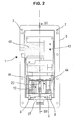
- FIG. 1 An illustrated embodiment of a weighing unit according to the invention for a Operamengenwaage 1 and 2 is provided with a housing 1 shown in FIG. which essentially has the basic shape of a unilaterally slightly bevelled cuboid, of a rectangular in Fig. 1 housing wall 2, a lower in Fig. 1 rectangular Housing wall 3, both extending orthogonal to the plane of the drawing of Fig. 1, two parallel to the plane of Fig. 1 side housing walls 4, which connect the upper housing wall 2 and the lower housing wall 3, and an orthogonal to the plane of Fig. 1 front housing wall 5, which the upper housing wall 2 and the lower housing wall 3 connects, is limited.
- the Housing 1 is open at its front side wall 5 opposite side and provided with a circumferential mounting flange 6 extending from the upper and lower Housing wall 2, 3 and the two side housing walls 4 from orthogonal to extends these housing walls.
- the front housing wall 5 extends from the mounting flange 6 opposite end of the lower housing wall 3 from under formation the bevel at an obtuse angle to the plane of the mounting flange 6, until they are approximately in the lower quarter of the distance between the lower housing wall 3 and the upper housing wall 2 is bent at an obtuse angle and from there runs parallel to the plane of the mounting flange 6 to the upper housing wall 2.
- the mounting flange 6 extends parallel to the plane of the drawing. In this view are mounting holes 7 visible.
- the housing 1 When installing the weighing unit in a subset balance is the housing 1 with his pointing in Fig. 2 to the viewer side of the Mounting flange 6 provided on a with a corresponding recess Mantle region of a vertically oriented with its axis prismatic support body set up a subset scale and passing through it with the mounting holes 7 Bolt bolted.
- Figs. 1 and 2 also partially leave a on the base plate 9 arranged load cell 10 and a cover 11 recognize which the load cell 10 at a distance with two parallel to the side housing walls 4
- Side walls 12 and an upper side wall 13 parallel to the base plate 9 Surrounds U-shaped, the U-legs directed with their free ends to the base plate 9 through are.
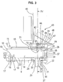
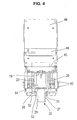
- the load cell 10 in the form of a bending beam 14 is formed, whose longitudinal axis is parallel to the plane of the drawing Fig. 3 and parallel to the base plate 9 and extends to the plane of FIG. 3 vertical cross-section is rectangular. From Fig. 4 it can be seen that the larger dimension this rectangular cross-section orthogonal to the base plate 9 and its smaller Dimension parallel to the base plate 9 extends. At its protruding from the housing 1 End of the bending beam 14 pointing to the base plate 9 and to this parallel mounting portion 15.
- the bending beam has 14 a recognizable in Figs. 2, 3 and 4 load application area 19, on which a Load bearing member 20 is fixed.
- This load introduction area 19 is at the base plate 9 opposite rectangular side of the bending beam 14 is formed.
- the remaining one Region 21 of this rectangle side is slightly opposite to the load introduction region 19 reset in the direction of the base plate 9.
- the remaining area 22 of the fastening region 15 having the rectangular side of the bending beam 14 is slightly set back relative to the attachment area 15 in the direction of the area 21.
- the load-bearing member 20 has a U-shaped region, the U-web 23 on the load introduction area 19 rests and is fixed there with two bolts 24, passing through formed in the U-web 23 openings and in corresponding Tapped holes 25 of the bending beam 14 are screwed. From the U-bridge 23 extend on both sides of the bending beam 14 and at a distance to the two U-legs 26 parallel to the orthogonal to the base plate 9 rectangular sides of the bending beam 14 to a cylindrically shaped region 27 of the load-bearing member 20, whose cylinder axis extends orthogonally to the base plate 9 and its to the bending beam 14 facing end face of the bending beam 14 is slightly spaced.
- the base plate 9 is a to the cylindrical portion 27 coaxial opening 28th formed, to which the cylindrical portion 27 of the load-receiving member 20 under all sides is arranged at the same radial distance.
- the cylindrical portion 27 is a step cylinder formed with a radial shoulder, one to the free end 29 of the cylindrical Area 27 facing annular abutment surface 30 forms.
- At this stop surface 30 is the radially inner edge of an axially deflectable annular membrane 31st at.
- the radially outer edge of the diaphragm 31 is through to the cylindrical portion 27 coaxial ring 32 on the bending beam 14 opposite side of the base plate 9 clamped at its adjacent to the edge of the opening 28 area.
- the free end 29 of the cylindrical portion 27 extends axially beyond the base plate 9 opposite radial end face of the ring 32 and serves to couple a weighing container (not shown).
- Both the base plate 9 and the U-web 23 of the load-bearing member 20 protrude beyond the load introduction region 19 having end of the bending beam 14 addition.
- a arranged orthogonally extending limiter 33 which serves as overload protection.
- the limiter 33 has a hollow cylindrical part 34 screwed to the base plate 9 and a complementary to the hollow cylindrical portion 34, screwed to the U-web 23 Part 35 on.
- This complementary part 35 engages with a radial Shoulder 36 radially tapered portion 37 under radial clearance in the inner cavity 38th of the hollow cylindrical part 34.
- the radial shoulder 36 of the complementary part is located in the rest position of the bending beam 14 at a distance to the facing her axial end 39 of the hollow cylindrical portion 34.
- the radial act Shoulder 36 and the axial end 39 as abutment areas the deflection of the bending beam Limit 14 to the distance set in between.
- the cavity 38 and the area 37 engaging in this cavity existing radial play the free deflection of the bending beam 14 in the direction of the Deflecting path.
- the between the base plate 9 and the mounting portion 15 of the bending beam 14 clamped plate-shaped part 16 is at a distance to the plane of the drawing 3 parallel sides of the bending beam 14 bent and extends from there from the base plate 9 away parallel to these side faces upwards.
- the cover 11 by means of Screws 40 are attached.
- Connector boards 41 for the electrical wiring of the load cell 10 arranged.
- Another plate-shaped part 42 is at one over the load introduction area 19 in Direction to the mounting portion 15 having the end of the bending beam 14th protruding portion of the U-web 23 of the load-bearing member 20 is screwed.
- This another plate-shaped part 42 also has mounting positions for fixing Connector boards on.
- Figs. 2 and 3 show a still further part 43 which is at a distance above the area of the bending beam 14 connected to the load-bearing member 20 arranged and supported on the base plate 9 with orthogonal support bolts 44.
- the part 43 has a portion 45 connected to the support bolts 44, which is parallel extends to the base plate 9, and an adjoining portion 46 which is orthogonal to the base plate 9 extends. Between the areas 45, 46 extends a roof-like inclined portion 47 on which the main board 48 of the load cell electronics is arranged.
- another U-shaped cover 49 is indicated in FIG. 3, which is arranged with its U-web parallel to the region 46 of the part 43.
- the mounting of the weighing unit takes place in such a way that first the load receiving member 20th is connected by means of the bolt 24 with the bending beam 14. Furthermore, the Membrane 31 defined by means of the ring 32 at the opening 28 of the base plate 9. Further is on the base plate 9, the hollow cylindrical portion 34 of the limiter 33 and on the U-web 23 of the load-bearing member 20, the complementary part 35 of the limiter 33 roughly pre-assembled.
- this alignment can also be brought about or be supported, that on the cylindrical portion 27 an annular assembly jig is placed, through which the radial distance between the cylindrical portion 27 and the inner ring opening 50 of the ring 31 is adjusted. In this aligned position Then the bolts 17 can be tightened. After that, if necessary, the used Assembly lessons are withdrawn again. Furthermore, the roughly pre-assembled Parts 34, 35 of the limiter 33 einjustiert and tightened their glands. Subsequently, the other components are mounted on the parts 16, 42 and 43. The way resulting unit is then using the bolts 8 in the housing. 1 established.
Landscapes
- Physics & Mathematics (AREA)
- General Physics & Mathematics (AREA)
- Measurement Of Force In General (AREA)
- Weight Measurement For Supplying Or Discharging Of Specified Amounts Of Material (AREA)
Applications Claiming Priority (2)
| Application Number | Priority Date | Filing Date | Title |
|---|---|---|---|
| DE10346697 | 2003-10-08 | ||
| DE2003146697 DE10346697A1 (de) | 2003-10-08 | 2003-10-08 | Wiegeeinheit für eine Teilmengenwaage und Verfahren zu deren Herstellung |
Publications (1)
| Publication Number | Publication Date |
|---|---|
| EP1522831A1 true EP1522831A1 (fr) | 2005-04-13 |
Family
ID=34306317
Family Applications (1)
| Application Number | Title | Priority Date | Filing Date |
|---|---|---|---|
| EP04017340A Withdrawn EP1522831A1 (fr) | 2003-10-08 | 2004-07-22 | Unité de pesage pour machine de pesage par combination et sa fabrication. |
Country Status (2)
| Country | Link |
|---|---|
| EP (1) | EP1522831A1 (fr) |
| DE (1) | DE10346697A1 (fr) |
Citations (4)
| Publication number | Priority date | Publication date | Assignee | Title |
|---|---|---|---|---|
| US4441569A (en) * | 1981-04-28 | 1984-04-10 | Kabushiki Kaisha Ishida Koki Seisakusho | Weighing apparatus |
| US4593778A (en) * | 1983-06-21 | 1986-06-10 | Kabushiki Kaisha Ishida Koki Seisakusho | Weighing machine with dummy load cell for error correction |
| DE3914192A1 (de) * | 1988-05-03 | 1989-11-16 | Ishida Scale Mfg Co Ltd | Kombinationswaage |
| EP0362567A2 (fr) * | 1988-09-07 | 1990-04-11 | Ishida Scales Mfg. Co., Ltd. | Dispositif étanche pour le pesage automatique |
Family Cites Families (2)
| Publication number | Priority date | Publication date | Assignee | Title |
|---|---|---|---|---|
| JPS59131120A (ja) * | 1983-01-17 | 1984-07-27 | Ishida Scales Mfg Co Ltd | 重量検出方法及び重量検出器構造 |
| US4616722A (en) * | 1985-03-28 | 1986-10-14 | Usm Corporation | Weighing apparatus with compartmentalized weighing bucket |
-
2003
- 2003-10-08 DE DE2003146697 patent/DE10346697A1/de not_active Withdrawn
-
2004
- 2004-07-22 EP EP04017340A patent/EP1522831A1/fr not_active Withdrawn
Patent Citations (4)
| Publication number | Priority date | Publication date | Assignee | Title |
|---|---|---|---|---|
| US4441569A (en) * | 1981-04-28 | 1984-04-10 | Kabushiki Kaisha Ishida Koki Seisakusho | Weighing apparatus |
| US4593778A (en) * | 1983-06-21 | 1986-06-10 | Kabushiki Kaisha Ishida Koki Seisakusho | Weighing machine with dummy load cell for error correction |
| DE3914192A1 (de) * | 1988-05-03 | 1989-11-16 | Ishida Scale Mfg Co Ltd | Kombinationswaage |
| EP0362567A2 (fr) * | 1988-09-07 | 1990-04-11 | Ishida Scales Mfg. Co., Ltd. | Dispositif étanche pour le pesage automatique |
Also Published As
| Publication number | Publication date |
|---|---|
| DE10346697A1 (de) | 2005-05-12 |
Similar Documents
| Publication | Publication Date | Title |
|---|---|---|
| EP0955530B1 (fr) | Balance avec une zone de couplage pour un poids de calibrage | |
| EP0819922B1 (fr) | Protection de chocs pour un dispositif de mesure de force | |
| EP0065176A2 (fr) | Dispositif pour appliquer une charge à un support sous forme d'une poutre | |
| EP0034656A1 (fr) | Plateforme de pesage et procédé pour la fabrication de telles plates-formes de pesage | |
| EP0080702A2 (fr) | Dispositif pour la mesure de force | |
| DE3331708A1 (de) | Vorrichtung zur kontrolle und/oder eichung einer drehmomentmessvorrichtung | |
| DE19540782C1 (de) | Oberschalige elektronische Waage mit zwei Übersetzungshebeln | |
| EP0104557A2 (fr) | Balance | |
| EP1564534A1 (fr) | Module à cellule de charge | |
| DE102013012507B4 (de) | Stabförmiger Kraftaufnehmer mit vereinfachtem Abgleich | |
| EP1754030B1 (fr) | Securite antisurcharge pour element dynamometrique | |
| EP0573806B1 (fr) | Balance de précision | |
| EP1701144B1 (fr) | Dispositif pour peser des produits uniformes | |
| DE2753549C2 (de) | Überlastsicherung für eine Kraftmeßeinrichtung | |
| EP1522831A1 (fr) | Unité de pesage pour machine de pesage par combination et sa fabrication. | |
| DE19910003A1 (de) | Überlastsicherung für Aufnehmer mit Dehnungsmeßstreifen | |
| EP1530035A1 (fr) | Cellule de mesure de force avec découplage de fixation par surfaces surélevées et courtes incisions | |
| EP1785704A1 (fr) | Module de pesage | |
| DE60119027T2 (de) | Rahmenstruktur für die Vakuumröhre eines Leistungsschaltermoduls | |
| DE3833291A1 (de) | Plattformwaage | |
| EP1382562A1 (fr) | Dispositif de détermination de charge | |
| DE102014013042B4 (de) | Kraftmessvorrichtung | |
| DE2352749C2 (de) | Meßvorrichtung zum getrennten Messen des Gewindeanteils und Kopfanteils des Anziehdrehmomentes einer Schraubenverbindung | |
| DE102019215294B4 (de) | Robotik-Kraftmesseinrichtung | |
| DE19516326C2 (de) | Gerät zur Messung von Differenzdruck |
Legal Events
| Date | Code | Title | Description |
|---|---|---|---|
| PUAI | Public reference made under article 153(3) epc to a published international application that has entered the european phase |
Free format text: ORIGINAL CODE: 0009012 |
|
| AK | Designated contracting states |
Kind code of ref document: A1 Designated state(s): AT BE BG CH CY CZ DE DK EE ES FI FR GB GR HU IE IT LI LU MC NL PL PT RO SE SI SK TR |
|
| AX | Request for extension of the european patent |
Extension state: AL HR LT LV MK |
|
| 17P | Request for examination filed |
Effective date: 20050908 |
|
| AKX | Designation fees paid |
Designated state(s): AT BE BG CH CY CZ DE DK EE ES FI FR GB GR HU IE IT LI LU MC NL PL PT RO SE SI SK TR |
|
| RAP1 | Party data changed (applicant data changed or rights of an application transferred) |
Owner name: METTLER-TOLEDO GARVENS GMBH |
|
| STAA | Information on the status of an ep patent application or granted ep patent |
Free format text: STATUS: THE APPLICATION IS DEEMED TO BE WITHDRAWN |
|
| 18D | Application deemed to be withdrawn |
Effective date: 20060527 |