EP1522725B1 - Windenergieanlage - Google Patents
Windenergieanlage Download PDFInfo
- Publication number
- EP1522725B1 EP1522725B1 EP04027646A EP04027646A EP1522725B1 EP 1522725 B1 EP1522725 B1 EP 1522725B1 EP 04027646 A EP04027646 A EP 04027646A EP 04027646 A EP04027646 A EP 04027646A EP 1522725 B1 EP1522725 B1 EP 1522725B1
- Authority
- EP
- European Patent Office
- Prior art keywords
- wind energy
- energy installation
- rotor blade
- installation according
- lightning
- Prior art date
- Legal status (The legal status is an assumption and is not a legal conclusion. Google has not performed a legal analysis and makes no representation as to the accuracy of the status listed.)
- Expired - Lifetime
Links
- 238000007599 discharging Methods 0.000 claims abstract description 7
- AZDRQVAHHNSJOQ-UHFFFAOYSA-N alumane Chemical group [AlH3] AZDRQVAHHNSJOQ-UHFFFAOYSA-N 0.000 claims description 13
- 239000004020 conductor Substances 0.000 claims description 12
- XAGFODPZIPBFFR-UHFFFAOYSA-N aluminium Chemical compound [Al] XAGFODPZIPBFFR-UHFFFAOYSA-N 0.000 claims description 4
- 229910052782 aluminium Inorganic materials 0.000 claims description 4
- 238000000465 moulding Methods 0.000 claims description 2
- 239000012811 non-conductive material Substances 0.000 claims description 2
- 238000009434 installation Methods 0.000 claims 25
- 238000002955 isolation Methods 0.000 claims 2
- 229920002430 Fibre-reinforced plastic Polymers 0.000 claims 1
- 239000004411 aluminium Substances 0.000 claims 1
- 239000011151 fibre-reinforced plastic Substances 0.000 claims 1
- 230000003068 static effect Effects 0.000 description 11
- 238000007600 charging Methods 0.000 description 2
- 238000007786 electrostatic charging Methods 0.000 description 2
- 150000001875 compounds Chemical class 0.000 description 1
- 238000011161 development Methods 0.000 description 1
- 230000018109 developmental process Effects 0.000 description 1
- 230000001939 inductive effect Effects 0.000 description 1
- 239000004922 lacquer Substances 0.000 description 1
- 238000000926 separation method Methods 0.000 description 1
Images


Classifications
-
- H—ELECTRICITY
- H02—GENERATION; CONVERSION OR DISTRIBUTION OF ELECTRIC POWER
- H02G—INSTALLATION OF ELECTRIC CABLES OR LINES, OR OF COMBINED OPTICAL AND ELECTRIC CABLES OR LINES
- H02G13/00—Installations of lightning conductors; Fastening thereof to supporting structure
- H02G13/40—Connection to earth
-
- F—MECHANICAL ENGINEERING; LIGHTING; HEATING; WEAPONS; BLASTING
- F03—MACHINES OR ENGINES FOR LIQUIDS; WIND, SPRING, OR WEIGHT MOTORS; PRODUCING MECHANICAL POWER OR A REACTIVE PROPULSIVE THRUST, NOT OTHERWISE PROVIDED FOR
- F03D—WIND MOTORS
- F03D1/00—Wind motors with rotation axis substantially parallel to the air flow entering the rotor
- F03D1/06—Rotors
- F03D1/065—Rotors characterised by their construction elements
-
- F—MECHANICAL ENGINEERING; LIGHTING; HEATING; WEAPONS; BLASTING
- F03—MACHINES OR ENGINES FOR LIQUIDS; WIND, SPRING, OR WEIGHT MOTORS; PRODUCING MECHANICAL POWER OR A REACTIVE PROPULSIVE THRUST, NOT OTHERWISE PROVIDED FOR
- F03D—WIND MOTORS
- F03D80/00—Details, components or accessories not provided for in groups F03D1/00 - F03D17/00
- F03D80/30—Lightning protection
- F03D80/301—Lightning receptor and down conductor systems in or on blades
-
- H—ELECTRICITY
- H02—GENERATION; CONVERSION OR DISTRIBUTION OF ELECTRIC POWER
- H02G—INSTALLATION OF ELECTRIC CABLES OR LINES, OR OF COMBINED OPTICAL AND ELECTRIC CABLES OR LINES
- H02G13/00—Installations of lightning conductors; Fastening thereof to supporting structure
-
- H—ELECTRICITY
- H02—GENERATION; CONVERSION OR DISTRIBUTION OF ELECTRIC POWER
- H02G—INSTALLATION OF ELECTRIC CABLES OR LINES, OR OF COMBINED OPTICAL AND ELECTRIC CABLES OR LINES
- H02G13/00—Installations of lightning conductors; Fastening thereof to supporting structure
- H02G13/80—Discharge by conduction or dissipation, e.g. rods, arresters, spark gaps
-
- F—MECHANICAL ENGINEERING; LIGHTING; HEATING; WEAPONS; BLASTING
- F05—INDEXING SCHEMES RELATING TO ENGINES OR PUMPS IN VARIOUS SUBCLASSES OF CLASSES F01-F04
- F05B—INDEXING SCHEME RELATING TO WIND, SPRING, WEIGHT, INERTIA OR LIKE MOTORS, TO MACHINES OR ENGINES FOR LIQUIDS COVERED BY SUBCLASSES F03B, F03D AND F03G
- F05B2240/00—Components
- F05B2240/20—Rotors
- F05B2240/30—Characteristics of rotor blades, i.e. of any element transforming dynamic fluid energy to or from rotational energy and being attached to a rotor
-
- Y—GENERAL TAGGING OF NEW TECHNOLOGICAL DEVELOPMENTS; GENERAL TAGGING OF CROSS-SECTIONAL TECHNOLOGIES SPANNING OVER SEVERAL SECTIONS OF THE IPC; TECHNICAL SUBJECTS COVERED BY FORMER USPC CROSS-REFERENCE ART COLLECTIONS [XRACs] AND DIGESTS
- Y02—TECHNOLOGIES OR APPLICATIONS FOR MITIGATION OR ADAPTATION AGAINST CLIMATE CHANGE
- Y02E—REDUCTION OF GREENHOUSE GAS [GHG] EMISSIONS, RELATED TO ENERGY GENERATION, TRANSMISSION OR DISTRIBUTION
- Y02E10/00—Energy generation through renewable energy sources
- Y02E10/70—Wind energy
- Y02E10/72—Wind turbines with rotation axis in wind direction
Definitions
- the invention relates to a wind turbine, such wind turbines of modern type, for example, a type E-40 or E-66 from Enercon, are regularly equipped with a lightning protection system, which, for example DE 44 36 290 . DE 198 26 086 . DE 195 01 267 . DE 44 45 899 . WO 00/14405 or WO 96/07825 is known. From the closest prior art DE 44 36197 is a wind turbine according to the preamble of claim 1 with a lightning protection device known.
- Such a rollover generates electromagnetic waves (EMV) with an extremely high bandwidth, because the rollover takes place almost in the form of a pulse, which ideally has an extreme bandwidth (ideally over an infinite bandwidth).
- EMV electromagnetic waves
- the invention is based on the proposal to discharge the electrostatic charges of the rotor blades continuously. Care must be taken to ensure that the voltage at the spark gaps just before a flashover can easily reach 20 to 30 kV, depending on the humidity.
- the apparatus for continuous discharge (discharge circuit) of the rotor blades must satisfy substantially two conditions, namely, first, the continuous discharge path must be so low as to avoid static charging of the rotor blades and, second, it must be capable of withstand voltage withstand 30 kV and more (such surge voltages occur in lightning strikes).
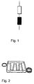
- the device for continuously discharging electrostatic charge of the rotor blades consists of a discharge circuit, the having a series connection of an ohmic bleeder resistor and an inductor.
- the leakage resistance preferably has a value of about 50 k ⁇ and the inductance preferably has a value of 10 ⁇ H or more.
- each static discharge rotor blade with a resistance of 50 k ⁇ is connected to ground potential when the in FIG. 1 represented circuit connects a rotor blade to the ground terminal of the ground potential.
- the ohmic resistance is formed by a wire resistor and if this is wound up at the same time, the ohmic resistance as well as the inductance can be made very space-saving.
- FIG. 2 the application shown in a view. This shows five wound wire wound resistors connected in series, which have corresponding supply lines.
- the execution of a wound wire resistor has the advantage that an equal voltage distribution over the entire length of the resistors is given.
- Another advantage of the invention consists in the very simple solution, which nevertheless very effective protection of the entire Ensures electronics of the wind turbine and a sudden (jerky) discharge of electrostatic charges with the help of the described Statikableiters granted.
- the static conductor (32) (the device for the continuous discharge of electrostatic charge) ultimately consists of a simple electrical impedance with an ohmic and an inductive component and the static conductor (32) is arranged parallel to the spark gap.
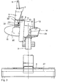
- Fig. 3 shows the arrangement of the static conductor according to the invention in a wind turbine.
- the wind turbine shown here has a machine carrier, which receives a rotor hub (30) on which rotor blades are arranged, and a generator coupled to the rotor hub (30).
- the machine frame 14 is rotatably mounted on a tower 3 about a vertical axis.
- the tower 3 is anchored in a foundation 4.
- a rotor blade 5 is shown.
- the tip of the rotor blade 5 is formed as an aluminum molding 6.
- On the rotor blade root 24 a rotor blade root 24 totally encircling aluminum ring 8 is arranged.
- Rod-shaped guide elements 7, which extend in the leading edge and at the trailing edge of the rotor blade, electrically connect the aluminum shaped part 6 of the tip with the aluminum ring 8 arranged on the rotor blade root 24.
- a catch rod 9 is arranged at the height of the aluminum ring 8 as a lightning discharge element.
- the catch rod 9 is connected via a transfer projection 11 an electrically conductive diverter ring to a predetermined distance, z. B. 3 mm, approximated. With her the Üeiteitungsvorsprung 11 facing away from the free end of the catch rod 9 is approximated on the aluminum ring 8 to a predetermined, approximately the same distance.
- the grounded diverter ring 10 is arranged coaxially with the rotor shaft.
- the approach of the Kochleitvorsprungs 11 is ensured during the complete rotation of the rotor blade 5.
- the machine driver 14 is surmounted by an additional catch rod 12, which is connected to the machine carrier 14 with an electrically conductive connection 13.
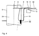
- the horizontal aluminum ring 8 is only partially guided around the rotor blade root.
- the lower end of the guide element 7 of the illustrated support means is electrically connected to the aluminum ring 8.
- the electrically conductive Blitzableitungsweg between the aluminum ring 8 and the diverter ring 10 is produced by the fishing rod 9, the like with clamps or the like. is mounted horizontally on the rotor hub cover 15 of electrically non-conductive material and thus rotates with the rotor blade 5.
- a cross connector 16 is arranged, which connects the catch rod 9 with the Matterleitvorsprung 11.
- the Studentsleitvorsprung 11 is perpendicular through the rotor hub trim 15 through the Ableitring 10 approximated to a certain distance.
- Fig. 5 also illustrates that the Ableitring 10 in the vicinity of the approach of the Matterleitvorsprunges 11 at the level of the cross connector 16 has a predetermined Blitzableitungsweg 17 in the form of a lower lacquer layer thickness.
- Fig. 5 also shows that the aluminum ring 8 is guided around the rotor blade root 24 in a semicircular shape in order to connect the two guide elements 7 together and to ensure an electrical operative connection to the catch rod 9 at the possible angle settings of the rotor blade.
- the fishing rod 9 has on its the aluminum ring 8 to a predetermined distance approximate free end 25 a field strength in comparison to the surrounding area increasing conical tip.
- Fig. 6 shows an electrically conductive connection between the machine frame 14 and the upper portion of the tower 3.
- a horizontal friction disc 20 is arranged coaxially with the axis of rotation of the machine frame 14.
- the machine carrier 14 has in a tower 3 facing area a lightning discharge element, which is designed as a contact pressure applied to the plunger 19.
- This plunger 19 is arranged perpendicular to the machine frame 14 in this area so that it presses on the friction plate 20 and thus produces an electrically conductive connection. Even with rotations of the machine carrier 14, this compound remains due to the grinding system.
- a lightning striking the wind turbine is derived as follows:
- a lightning striking a rotor blade 5 is first discharged into the machine frame 14. Starting from the aluminum mold part 6 or a guide element 7, the lightning is discharged via the guide elements 7 in the aluminum ring 8. Regardless of the current rotor blade angle of the flash from the aluminum ring 8 is then transferred via the catch rod 9 in the diverter ring 10. About the predetermined lightning discharge path 17 of the diverter ring 10 of the lightning is introduced via not shown conductive connections in the machine frame 14.
- a striking into the additional catch rod 12 flash is also introduced via the connection 13 in the machine frame 14.
- the lightning discharge is thus ensured regardless of the current rotational position of the machine carrier 14.
- the further lightning discharge takes place via the tower 3, the foundation 4 and the ringers 27 running into the ground.
- the invention shows how, on the one hand, a continuous discharge of electrostatic charges from a rotor blade can take place in an excellent manner, but how, on the other hand, lightning strikes in the rotor blade can be dissipated without causing damage to the wind turbine. While the electrostatic charges are discharged directly via the static conductor and via the hub, charges resulting from a lightning strike are led past the hub, in particular past the hub's bearing. The lines for electrostatic charges as well as lightning currents from the rotor blade tip to the blade root area may be the same. To protect the wind turbine but must be taken to ensure that lightning strikes are not performed on the hub or the bearings of the hub.
Landscapes
- Engineering & Computer Science (AREA)
- Life Sciences & Earth Sciences (AREA)
- Sustainable Development (AREA)
- Sustainable Energy (AREA)
- Chemical & Material Sciences (AREA)
- Combustion & Propulsion (AREA)
- Mechanical Engineering (AREA)
- General Engineering & Computer Science (AREA)
- Wind Motors (AREA)
- Elimination Of Static Electricity (AREA)
- Buildings Adapted To Withstand Abnormal External Influences (AREA)
- Basic Packing Technique (AREA)
- Steroid Compounds (AREA)
- Control Of Eletrric Generators (AREA)
- Acyclic And Carbocyclic Compounds In Medicinal Compositions (AREA)
- Thin Film Transistor (AREA)
- Saccharide Compounds (AREA)
- Pharmaceuticals Containing Other Organic And Inorganic Compounds (AREA)
Description
- Die Erfindung betrifft eine Windenergleanlage, Solche Windenergieanlagen modernen Typs, beispielsweise ein vom Typ E-40 oder E-66 der Firma Enercon, sind regelmäßig mit einem Blitzschutzsystem ausgestattet, welches beispielsweise aus
DE 44 36 290 ,DE 198 26 086 ,DE 195 01 267 ,DE 44 45 899 ,WO 00/14405 WO 96/07825 DE 44 36197 ist eine Windenergieanlage nach dem Oberbegriff des Anspruchs 1 mit einer Blitzschutzeinrichtung bekannt. - Bei solchen wie vorbeschrieben bekannten Bützschutzsystemen kann sich dann, wenn das Rotorblatt galvanisch von der Nabe getrennt ist, das jeweilige Rotorblatt statisch aufladen. Diese elektrostatische Aufladung eines Rotorblattes entsteht durch die Luftreibung der rotierenden Rotorblätter des Rotors einer Windenergieanlage. Je nach Luftfeuchtigkeit bzw. anderer ungünstiger Witterungseinflüsse landen sich die Rotorblätter (bzw. deren Blitzschutzsysteme) schneller oder langsamer auf. Die statische Aufladung erfolgt solange, bis die Überschlagsspannung der Luftstrecke erreicht wird. Dann erfolgt der überschlag und das gesamte System bzw, die Rotorblätter entladen sich. Ein solcher Überschlag erzeugt elektromagnetische Wellen (EMV) mit einer extrem hohen Bandbreite, weil der Überschlag quasi in Form eines Impulses erfolgt, der idealerweise über eine extreme Bandbreite (idealerweise über eine unendliche Bandbreite) verfügt. Diese schlagartigen Entladungen, die nicht auf einen Blitzeinschlag wegen eines Gewitters, sondern von der elektrostatischen Aufladung der Rotoren herrührt, stören die gesamte Elektronik der Windenergieanlage, die sich im Umfeld des überschlage befindet, wie beispielsweise die Computer oder Mikroprozessoren die ein einzelnes Rotorblatt steuern und regeln. Betroffen sind aber auch andere elektronische Einrichtungen der Windenergieanlage, die sich in der Gondel oder in der Nähe der Funkenüberschlagsstrecke befinden. Durch das Aufladen der rotierenden Rotorblätter kommt es regelmäßig zu Überschlägen an der Funkenstrecke mit ebenso regelmäßigen Störungen der Elektronik, was schon zum Schutze der gesamten elektronischen Anlageeinrichtungen nicht erwünscht ist.
- Es ist Aufgabe der vorliegenden Erfindung, die vorgenannten Nachteile zu vermeiden und insbesondere die Zahl der Störung an der Elektronik wegen der überschläge an der Funkenstrecke zu minimieren.
- Die Aufgabe wird mittels einer Windenergieanlage mit den Merkmalen nach Anspruch 1 gelöst. Vorteilhafte Weiterbildungen sind in den Unteransprüchen beschrieben.
- Die Erfindung beruht auf dem Vorschlag, die elektrostatischen Ladungen der Rotorblätter kontinuierlich zu entladen. Hierbei ist darauf zu achten, dass die Spannung an den Funkenstrecken kurz vor einem Überschlag je nach Feuchtigkeit leicht 20 bis 30 kV erreichen kann. Mithin muss die Vorrichtung zur kontinuierlichen Entladung (Entladeschaltung) der Rotorblätter im wesentlichen zwei Bedingungen erfüllen, nämlich erstens, die kontinuierliche Entladestrecke muss so niederohmig sein, dass eine statische Aufladung der Rotorblätter vermieden wird und zweitens muss sie in der Lage sein, einer Stoß-Spannung in Höhe von 30 kV und mehr zu widerstehen (solche Stoß-Spannungen stellen sich bei Blitzeinschlägen ein).
- Die Erfindung wird nachfolgend anhand von zeichnerischen Darstellungen näher erläutert. In den Zeichnungen stellen dar:
- Fig. 1
- eine Reihenschaltung eines ohmschen Widerstandes und einer Induktivität;
- Fig. 2
- eine Ausführung der Erfindung mit fünf in Reihe geschalteten, gewickelten Drahtwiderständen;
- Fig. 3
- eine Ansicht/ein Teilquerschnitt durch eine erfindungsgemäße Windenergieanlage;
- Fig. 4
- eine vergrößerte Darstellung des Ausrisses III aus
Fig. 3 ; - Fig. 5
- eine weitere vergrößerte Detailansicht aus
Fig. 3 ; und - Fig. 6
- eine Detallansicht aus dem Bereich V in
Fig, 3 . - Es ist besonders zweckmäßig, wenn die Vorrichtung zur kontinuierlichen Entladung elektrostatischer Ladung der Rotorblätter aus einer Entladeschaltung besteht, die eine Reihenschaltung eines ohmschen Ableitwiderstandes und einer Induktivität aufweist. Dies ist in
Figur 1 dargestellt. Hierbei weist der Ableitwiderstand vorzugsweise einen Wert von ca. 50 kΩ und die Induktivität vorzugsweise einen Wert von 10 µH oder mehr auf. - Während der statischen Entladung der Rotorblätter, ist die Induktivität nicht in Funktion, da die Ableitströme einen Gleichstrom mit sehr kleiner Amplitude darstellen. Somit ist jedes Rotorblatt für die statische Entladung mit einem Widerstand von 50 kΩ mit dem Erdpotential verbunden, wenn die in
Figur 1 dargestellte Schaltung ein Rotorblatt mit dem Erdanschluss des Erdpotentials verbindet. - Im Falle eines Blitzeinschlages (aufgrund eines Gewitters) steigt die Spannung an der Funkenstrecke (die Entladungsschaltung nach
Figur 1 ) sehr hoch an. Die Höhe der Spannung ist von dem Abstand, dem Krümmungsradius der Kontaktspitzen und der Luftfeuchtigkeit abhängig. Die Induktivität begrenzt nun den Anstieg des Stromes, der durch den statischen Ableiter (R+L) fließt. Damit ist ein ausreichender passiver Schutz für den Ableitwiderstand gegeben. - Besonders vorteilhaft ist es, wenn der ohmsche Widerstand durch ein Drahtwiderstand gebildet wird und wenn dieser gleichzeitig aufgewickelt ist, kann der ohmsche Widerstand wie auch die Induktivität sehr platzsparend gestaltet werden. Dies ist in
Figur 2 der Anmeldung in einer Ansicht gezeigt. Hierbei sind fünf in Reihe geschaltete, gewickelte Drahtwiderstände dargestellt, die über entsprechende Zuleitungen verfügen. - Die Ausführung eines gewickelten Drahtwiderstandes hat den Vorteil, dass eine gleiche Spannungsverteilung über die gesamte Länge der Widerstände gegeben ist.
- Ein weiterer Vorteil der erfindungsgemäßen Ausbildung besteht in der sehr einfachen Lösung, die gleichwohl einen sehr wirksamen Schutz der gesamten Elektronik der Windenergieanlage gewährleistet und eine schlagartige (stoßartige) Entladung von elektrostatischen Ladungen mit Hilfe des beschriebenen Statikableiters gewährt.
- Der Statikableiter (32) (die Vorrichtung zur kontinuierlichen Entladung elektrostatischer Ladung) besteht letztlich aus einer einfachen elektrischen Impedanz mit einer ohmschen und einer induktiven Komponente und der Statikableiter (32) ist parallel zur Funkenstrecke angeordnet.
-
Fig. 3 zeigt die Anordnung des erfindungsgemäßen Statikableiters bei einer Windenergieanlage. Die hierbei dargestellte Windenergieanlage hat einen Maschinenträger, der eine Rotornabe (30), an der Rotorblätter angeordnet sind, sowie einen an die Rotomabe (30) gekoppelten Generator aufnimmt. Der Maschinenträger 14 ist auf einem Turm 3 um eine lotrechte Achse drehbar angeordnet. Der Turm 3 ist in einem Fundament 4 verankert. Zu dessen Übersicht ist ein Rotorblatt 5 dargestellt. Die Spitze des Rotorblattes 5 ist als Aluminiumformteil 6 ausgebildet. Auf der Rotorblattwurzel 24 ist ein die Rotorblattwurzel 24 total umlaufender Aluminiumring 8 angeordnet. Stangenförmige Leitelemente 7, die in der Vorderkante und an der Hinterkante des Rotorblatts verlaufen, verbinden das Aluminiumformteil 6 der Spitze elektrisch leitend mit dem auf der Rotorblattwurzel 24 angeordneten Aluminiumring 8. - Im Bereich der Rotorblattwurzel 24 ist auf Höhe des Aluminiumrings 8 eine Fangstange 9 als Blitzableitungsorgan angeordnet. Die Fangstange 9 ist über einen Überleitungsvorsprung 11 einem elektrisch leitenden Ableitring bis auf einen vorbestimmten Abstand, z. B. 3 mm, angenähert. Mit ihrem dem Übedeitungsvorsprung 11 abgewandten freien Ende ist die Fangstange 9 auf dem Aluminiumring 8 bis auf einen vorbestimmten, etwa gleichen Abstand angenähert.
- Der geerdete Ableitring 10 ist koaxial zur Rotorwelle angeordnet. Somit ist die Annäherung des Überleitvorsprungs 11 während der vollständigen Drehung des Rotorblatts 5 gewährleistet.
- Der Maschinendreher 14 wird von einer zusätzlichen Fangstange 12 überragt, die an den Maschinenträger 14 mit einer elektrisch leitenden Verbindung 13 angeschlossen ist.
- Zwischen dem Aluminiumring 8 und dem Blattadapter (31) ist der Statikableiter (32) leitend angeordnet. Hierüber kann die statische Ableitung der Rotorblätter wie vorbeschrieben erfolgen.
- Die in
Fig. 3 dargestellte Ansicht ist in vergrößerter Form nochmals inFig. 4 gezeigt. - Hierbei ist der horizontale Aluminiumring 8 nur abschnittsweise um die Rotorblattwurzel herumgeführt. Das untere Ende des Leitelementes 7 der dargestellten Stützeinrichtung ist mit dem Aluminiumring 8 elektrisch leitend verbunden. Der elektrisch leitende Blitzableitungsweg zwischen dem Aluminiumring 8 und dem Ableitring 10 wird durch die Fangstange 9 hergestellt, die mit Schellen o.dgl. auf der Rotornabenverkleidung 15 aus elektrisch nicht leitendem Material waagerecht liegend befestigt ist und sich somit mit dem Rotorblatt 5 mitdreht. An dem dem Rotorblatt 5 abgewandten Ende der Fangstange 9 ist ein Kreuzverbinder 16 angeordnet, der die Fangstange 9 mit dem Überleitvorsprung 11 verbindet. Der Überleitvorsprung 11 ist senkrecht durch die Rotornabenverkleidung 15 hindurch dem Ableitring 10 bis auf einen bestimmten Abstand angenähert.
- Die Darstellung in
Fig. 5 verdeutlicht auch, dass der Ableitring 10 im Bereich der Annäherung des Überleitvorsprunges 11 auf Höhe des Kreuzverbinders 16 einen vorbestimmten Blitzableitungsweg 17 in Form einer geringeren Lackschichtdicke aufweist.Fig. 5 zeigt auch, dass der Aluminiumring 8 um die Rotorblattwurzel 24 halbkreisförmig herumgeführt ist, um beide Leitelemente 7 miteinander zu verbinden und um bei den möglichen Winkeleinstellungen des Rotorblattes eine elektrische Wirkverbindung zur Fangstange 9 zu gewährleisten. Die Fangstange 9 weist an ihrem dem Aluminiumring 8 bis auf einen vorbestimmten Abstand angenäherten freien Ende 25 eine die Feldstärke im Vergleich zur Umgebung erhöhende kegelförmige Spitze auf. -
Fig. 6 zeigt eine elektrisch leitende Verbindung zwischen dem Maschinenträger 14 und dem oberen Bereich des Turms 3. In diesem Bereich des Turms 3 ist eine waagerecht liegende Reibscheibe 20 koaxial zur Drehachse des Maschinenträgers 14 angeordnet. Der Maschinenträger 14 hat in einem den Turm 3 zugekehrten Bereich ein Blitzableitungselement, das als mit einem Anpressdruck beaufschlagter Stößel 19 ausgebildet ist. Dieser Stößel 19 ist in diesem Bereich so am Maschinenträger 14 senkrecht angeordnet, dass er auf die Reibscheibe 20 drückt und somit eine elektrisch leitende Verbindung herstellt. Auch bei Drehungen des Maschinenträgers 14 bleibt diese Verbindung aufgrund der schleifenden Anlage bestehen. - Ein in die Windenergieanlage einschlagender Blitz wird folgendermaßen abgeleitet:
- Ein in ein Rotorblatt 5 einschlagender Blitz wird zunächst in den Maschinenträger 14 abgeleitet. Ausgehend vom Aluminiumformteil 6 oder einem Leitelement 7 wird der Blitz über die Leitelemente 7 in den Aluminiumring 8 abgeleitet. Unabhängig vom momentanen Rotorblattwinkel wird der Blitz vom Aluminiumring 8 dann über die Fangstange 9 in den Ableitring 10 übergeleitet. Über den vorbestimmten Blitzableitungsweg 17 des Ableitringes 10 wird der Blitz über nicht dargestellte leitende Verbindungen in den Maschinenträger 14 eingeleitet.
- Ein in die zusätzliche Fangstange 12 einschlagender Blitz wird über die Verbindung 13 gleichfalls in den Maschinenträger 14 eingeleitet.
- Die Blitzableitung vom Maschinenträger 14 in den Turm 3 erfolgt über die sich in schleifender Anlage befindenden Stößel 19 und Reibscheibe 20. Die Blitzableitung ist somit auch unabhängig von der momentanen Drehstellung des Maschinenträgers 14 gewährleistet.
- Die weitere Blitzableitung erfolgt über den Turm 3, das Fundament 4 und die in das Erdreich laufenden Ringerder 27.
- Wie beschrieben, zeigt die Erfindung auf, wie einerseits in hervorragender Weise eine kontinuierliche Entladung von elektrostatischen Ladungen von einem Rotorblatt erfolgen kann, wie andererseits aber auch Blitzeinschläge im Rotorblatt abgeführt werden können, ohne Schäden an der Windenergieanlage zu verursachen. Während die elektrostatischen Ladungen über den Statikableiter und über die Nabe direkt abgeführt werden, werden Ladungen, die von einem Blitzschlag herrühren an der Nabe vorbei, insbesondere am Lager der Nabe vorbei abgeführt. Die Leitungen für elektrostatische Ladungen wie auch Blitzströme von der Rotorblattspitze bis zum Blattwurzelbereich können die gleichen sein. Zum Schutz der Windenergieanlage muss aber dafür gesorgt werden, dass Blitzeinschläge nicht über die Nabe bzw. die Lager der Nabe geführt werden.
- Die Auftrennung der verschiedenen Ladungswege für die elektrostatische Ladung einerseits und Blitzströme andererseits ist äußerst effektiv und konnte bei Windenergieanlagen sehr erfolgreich getestet werden. Der Aufwand ist insgesamt gering.
- Mit der Erfindung ist es möglich, dass Störungen, die einerseits von der elektrostatischen Aufladung der Rotorblätter herrühren könnten oder auch vom Blitzeinschlag, deutlich verringert werden können. Die besondere Kombination aus der Ableitung elektrostatischer Ströme und der Blitzströme über unterschiedliche Leitungswege hat sich bei mehreren Anlagen als überaus erfolgreich bewiesen.
Claims (22)
- Windenergieanlage mit einem Maschinenträger, der auf einem Unterbau drehbar angeordnet ist, mit einer auf dem Maschinenträger (14) gelagerten Motorwelle mit einer Rotomabe (30) und mit mindestens einem Rotorblatt (5) und gekennzeichnet durch eine Vorrichtung (32) zur Kontinuierlichen Entladung elektrostatischer Ladung von wenigstens einem Rotorblatt (5) der Windenergieanlage,
- Windenergieanlage nach Anspruch 1,
dadurch gekennzeichnet, dass die Vorrichtung (32) zur kontinuierlichen Entladung aus einer Reihenschaltung eines ohmschen Widerstandes und eine Induktivität besteht und die Schaltung elektrisch das Rotorblatt (5) mit einem Erdungsanschluss verbindet. - Windenergieanlage nach Anspruch 1 oder 2,
dadurch gekennzeichnet, dass die Vorrichtung (32) zur kontinuierlichen Entladung parallel zu einer Funkenstrecke eines Blitzschutzsystems der Windenergieanlage geschaltet ist. - Windenergieanlage nach einem der vorherigen Ansprüche,
dadurch gekennzeichnet, dass der ohmsche Widerstand ein Widerstand von wenigstens 10 kΩ, vorzugsweise 50kΩ aufweist, - Windenergieanlage nach einem der vorherigen Ansprüche,
dadurch gekennzeichnet, dass die Induktivität wenigstens 2µH, vorzugsweise größer als 10 µH ist. - Windenergieanlage nach einem der vorherigen Ansprüche,
dadurch gekennzeichnet, dass die induktivität aus einem gewickelten Drahtwiderstand besteht. - Windenergieanlage nach einem der vorherigen Ansprüche,
dadurch gekennzeichnet, dass der ohmsche Widerstand aus einem Drahtwiderstand besteht. - Windenergieanlage nach einem der vorhergehenden Ansprüche,
dadurch gekennzeichnet, dass die Vorrichtung (32) zur kontinuierlichen Entladung; elektrostatischer Ladung einerseits mit dem elektrischen Blitzableiteranschluss (8) des Rotorblattes (5) und andererseits mit dem Anschluss am Blattadapter (31) des Rotorblattes (5) elektrisch verbunden ist. - Windenergieanlage nach Anspruch 8,
dadurch gekennzeichnet, dass Ladungen, die über die Vorrichtung (32) zur kontinuierlichen Entladung elektrostatischer Ladung abgeführt werden, über die Nabe (30) der Windenergieanlage abgeführt werden. - Windenergieanlage nach einem der vorhergehenden Ansprüche,
gekennzeichnet durch eine Blitzschutzüberleitung von den Rotorblättern (5) zu einem feststehenden, elektrisch leitenden Bauteil des Maschinenträgers (14), der geerdet ist, wobei die Blitzschutzüberleitung als ein im Bereich der Rotorblattwurzel (24) in einem Isolations-Abstand zur Rotornabe (30) angeordnetes, mit der Rotorblattwurzel (24) in elektrischer Wirkverbindung stehendes Blitzableitungsorgan ausgebildet ist, das einen Überleitungsvorsprung (11) aufweist, der dem feststehenden, elektrisch leitenden Bauteil des Maschinenträgers (14) bis auf einen vorbestimmten Abstand angenähert ist. - Windenergieanlage nach Anspruch 10,
dadurch gekennzeichnet, dass das Blitzableitungsorgan eine Fangstange (9) ist. - Windenergieanlage nach Anspruch 10 oder 11,
dadurch gekennzeichnet, dass das feststehende, elektrisch leitende Bauteil des Maschinenträgers (14) ein koaxial zur Rotorwelle angeordneter Ableitring (10) ist und dass dieser in seinem dem Überleitungsvorsprung (11) zugekehrten Bereich einen vorbestimmten Blitzableitungsweg (17) aufweist, - Windenergieanlage nach Anspruch 11,
dadurch gekennzeichnet, dass die Fangstange (9) mit ihrem dem Überleitungsvorsprung (11) abgewandten freien Ende (25) einem auf der Rotorblattwurzel (24) angeordneten, elektrischen Leitelement bis auf einen vorbestimmten Abstand angenähert ist. - Windenergieanlage nach einem der vorherigen Ansprüche
dadurch gekennzeichnet, dass jedes Rotorblatt (5) an seiner Spitze und in einem Isolations-Abstand zur Rotornabe (30) auf seiner Rotorblattwurzel (24) angeordnete, elektrische Leitelemente aufweist, die miteinander elektrisch leitend verbunden sind. - Windenergieaniage nach Anspruch 14,
dadurch gekennzeichnet, dass das an der Spitze des Rotorblattes (5) angeordnete Leitelement als Aluminiumformteil (6) ausgebildet ist. - Windenergieanlage nach Anspruch 14 oder 15,
dadurch gekennzeichnet, dass in der Vorderkante und in der Hinterkante jedes Rotorblattes (5) elektrische Leitelemente (7) angeordnet sind, welche die an der Spitze des Rotorblattes (5) und auf seiner Rotorblattwurzel (24) angeordneten Leitelemente elektrisch leitend verbinden. - Windenergieanlage nach einem der Ansprüche 13 bis 16,
dadurch gekennzeichnet, dass das auf der Rotorblattwurzel (24) angeordnete Leitelement ein auf der Oberfläche der Rotorblattwurzel (24) mindestens absonittsweise horizontal umlaufender Aluminiumring (8) ist. - Windenergieanlage nach einem der vorherigen Ansprüche,
dadurch gekennzeichnet, dass in einem Bereich des Maschinenträgers (14), der dem Unterbau zugekehrt ist, ein Blitzableitungselement angeordnet ist, das sich mit einem elektrisch leitenden Bauelement des Unterbaus in schleifender Anlage befindet. - Windenergieanlage nach Anspruch 18,
dadurch gekennzeichnet, dass das Blitzableitungselement als ein mit einem Anpressdruck beaufschlagter Stößel (19) ausgebildet ist. - Windenergieanlage nach Anspruch 18 oder 19,
dadurch gekennzeichnet, dass das elektrisch leitende Bauelement des Unterbaus eine Reibscheibe (20) ist, die im oberen Bereich des Unterbaus in einer waagerechten Ebene und koaxial zur Drehachse des Maschinenträgers (14) liegend angeordnet ist. - Windenergieanlage nach einem der vorherigen Ansprüche,
dadurch gekennzeichnet, dass das Rotorblatt (5) aus einem elektrischen Nichtleitermaterial wie beispielsweise glasfaserverstärktem Kunststoff besteht, - Windenergieanlage nach einem der vorherigen Ansprüche,
dadurch gekennzeichnet, dass sie eine Blitzschutzeinrichtung mit einem Blitzableitungsorgan aufweist und dass im Bereich der Rotorblattnabe (30) die elektrostatischen Ladungen über einen anderen Weg abgeführt werden als bei einen Blitz eingeprägte Ladungen, wobei die elektrostatischen Ladungen über die Nabe (30) und die beim Blitz eingeprägten Ladungen an der Nabe (30) vorbei abgeführt werden.
Priority Applications (1)
| Application Number | Priority Date | Filing Date | Title |
|---|---|---|---|
| CY20121100234T CY1112593T1 (el) | 2000-05-06 | 2012-03-08 | Ανεμογεννητρια |
Applications Claiming Priority (4)
| Application Number | Priority Date | Filing Date | Title |
|---|---|---|---|
| DE10022128 | 2000-05-06 | ||
| DE10022128A DE10022128C1 (de) | 2000-05-06 | 2000-05-06 | Windenergieanlage |
| PCT/EP2001/002375 WO2001086144A1 (de) | 2000-05-06 | 2001-03-02 | Windenergieanlage |
| EP01917054A EP1282775B1 (de) | 2000-05-06 | 2001-03-02 | Windenergieanlage |
Related Parent Applications (2)
| Application Number | Title | Priority Date | Filing Date |
|---|---|---|---|
| EP01917054A Division EP1282775B1 (de) | 2000-05-06 | 2001-03-02 | Windenergieanlage |
| EP01917054.7 Division | 2001-03-02 |
Publications (4)
| Publication Number | Publication Date |
|---|---|
| EP1522725A2 EP1522725A2 (de) | 2005-04-13 |
| EP1522725A3 EP1522725A3 (de) | 2005-05-25 |
| EP1522725B1 true EP1522725B1 (de) | 2012-02-15 |
| EP1522725B2 EP1522725B2 (de) | 2019-09-25 |
Family
ID=7641029
Family Applications (2)
| Application Number | Title | Priority Date | Filing Date |
|---|---|---|---|
| EP04027646.1A Expired - Lifetime EP1522725B2 (de) | 2000-05-06 | 2001-03-02 | Windenergieanlage |
| EP01917054A Expired - Lifetime EP1282775B1 (de) | 2000-05-06 | 2001-03-02 | Windenergieanlage |
Family Applications After (1)
| Application Number | Title | Priority Date | Filing Date |
|---|---|---|---|
| EP01917054A Expired - Lifetime EP1282775B1 (de) | 2000-05-06 | 2001-03-02 | Windenergieanlage |
Country Status (22)
| Country | Link |
|---|---|
| US (1) | US6932574B2 (de) |
| EP (2) | EP1522725B2 (de) |
| JP (1) | JP3907477B2 (de) |
| KR (4) | KR100923009B1 (de) |
| CN (1) | CN1239823C (de) |
| AT (2) | ATE545783T1 (de) |
| AU (1) | AU778511B2 (de) |
| BR (1) | BR0110646B1 (de) |
| CA (1) | CA2408295C (de) |
| CY (1) | CY1112593T1 (de) |
| DE (2) | DE10022128C1 (de) |
| DK (2) | DK1282775T3 (de) |
| ES (2) | ES2381783T5 (de) |
| HK (1) | HK1054419B (de) |
| MA (1) | MA25667A1 (de) |
| MX (1) | MXPA02010883A (de) |
| NO (1) | NO324933B1 (de) |
| NZ (1) | NZ522424A (de) |
| PT (2) | PT1282775E (de) |
| TR (1) | TR200202455T2 (de) |
| WO (1) | WO2001086144A1 (de) |
| ZA (1) | ZA200209218B (de) |
Families Citing this family (71)
| Publication number | Priority date | Publication date | Assignee | Title |
|---|---|---|---|---|
| DE10022128C1 (de) † | 2000-05-06 | 2001-12-20 | Aloys Wobben | Windenergieanlage |
| US7249935B2 (en) * | 2002-06-19 | 2007-07-31 | Neg Micon A/S | Lightning protection means for a wind turbine |
| DK177270B1 (da) * | 2002-11-12 | 2012-09-10 | Lm Wind Power As | Lynbeskyttelse af pitchreguleret vindmøllevinge |
| JP2005019390A (ja) * | 2003-05-30 | 2005-01-20 | Norio Murazaki | 避雷装置 |
| DK200300882A (da) | 2003-06-12 | 2004-12-13 | Lm Glasfiber As | Registrering af lynnedslag, herunder i vindenergianlæg |
| EP1668246B1 (de) * | 2003-09-29 | 2014-10-29 | Vestas Wind Systems A/S | Blitzschutzsystem für windturbinenschaufel |
| JP4313364B2 (ja) * | 2003-11-20 | 2009-08-12 | ヴェスタス,ウィンド,システムズ エー/エス | 風力タービン、雷接続手段、方法及びその使用 |
| JP4580169B2 (ja) * | 2004-02-05 | 2010-11-10 | 富士重工業株式会社 | 風車用分割型ブレード及び風車の耐雷装置 |
| DE102004012946B4 (de) * | 2004-03-17 | 2006-03-23 | Stemmann-Technik Gmbh | Windenergieanlage |
| US7377750B1 (en) * | 2004-03-19 | 2008-05-27 | Northern Power Systems, Inc. | Lightning protection system for a wind turbine |
| DE102005017865B4 (de) * | 2005-04-19 | 2007-05-10 | Repower Systems Ag | Wartung des Blitzschutzes einer Windenergieanlage |
| ES2265776B1 (es) | 2005-08-01 | 2008-02-01 | GAMESA INNOVATION & TECHNOLOGY, S.L. | Sistema de transmision de rayos sin contacto. |
| JP4598636B2 (ja) * | 2005-09-14 | 2010-12-15 | 鹿島建設株式会社 | 風力発電装置及び風力発電設備 |
| JP4695482B2 (ja) * | 2005-10-06 | 2011-06-08 | 株式会社荏原製作所 | 風車ブレードの誘雷方法及び誘雷装置、風力発電装置の避雷方法及び避雷装置 |
| US7502215B2 (en) | 2005-11-18 | 2009-03-10 | General Electric Company | Systems and methods for directing a current |
| US7551414B2 (en) * | 2005-12-15 | 2009-06-23 | Lsi Corporation | Electrostatic discharge series protection |
| MX2009000466A (es) * | 2006-07-14 | 2009-03-13 | Vestas Wind Sys As | Turbina eolica que comprende una estructura de gabinete para formar una jaula de faraday. |
| DK200800942A (da) | 2007-07-24 | 2009-01-25 | Gen Electric | Wind turbine protection |
| US20090246025A1 (en) * | 2008-03-28 | 2009-10-01 | General Electric Company | Wind turbine protection |
| DE102007052525B4 (de) * | 2007-11-01 | 2009-08-27 | Innovative Windpower Ag | Vorrichtung zum Ableiten eines Blitzes bei einer Windenergieanlage |
| CN101463802B (zh) * | 2007-12-21 | 2011-05-18 | 广东明阳风电技术有限公司 | 风力发电机组防雷保护系统 |
| KR100934792B1 (ko) * | 2007-12-28 | 2009-12-31 | 주식회사 효성 | 풍력발전기의 접지 장치 |
| US8137074B2 (en) | 2008-08-21 | 2012-03-20 | General Electric Company | Wind turbine lightning protection system |
| EP2166227B1 (de) * | 2008-09-18 | 2016-01-06 | Siemens Aktiengesellschaft | Blitzschutzsystem für eine Windturbine |
| US7942640B2 (en) * | 2009-03-19 | 2011-05-17 | General Electric Company | Method and apparatus for use in protecting wind turbine blades from lightning damage |
| GB2469520A (en) * | 2009-04-17 | 2010-10-20 | Tyco Electronics Ltd Uk | Wind Turbine Lightning Protection And Monitoring Systems |
| DE102009017824B4 (de) * | 2009-04-20 | 2011-03-17 | Suzlon Energy Gmbh | Übertragungsvorrichtung für eine Windturbine |
| IT1393707B1 (it) * | 2009-04-29 | 2012-05-08 | Rolic Invest Sarl | Impianto eolico per la generazione di energia elettrica |
| US8342805B2 (en) * | 2009-06-25 | 2013-01-01 | General Electric Company | Transversal conduction lightning protection system |
| ES2357063B2 (es) * | 2009-10-06 | 2012-01-24 | Líneas Y Cables, S.A. | Sistema de protección de aerogeneradores frenta a descargas atmosféricas. |
| DE102009046586B4 (de) * | 2009-11-10 | 2012-02-23 | Nordex Energy Gmbh | Blattspitze für ein Rotorblatt einer Windenergieanlage und Verfahren zur Montage der Blattspitze an ein Rotorblatt |
| US9097238B2 (en) | 2009-11-12 | 2015-08-04 | Siemens Aktiengesellschaft | Lightning protection for a nacelle of a wind turbine |
| US9157419B2 (en) | 2009-12-09 | 2015-10-13 | Siemens Aktiengesellschaft | Lightning protection system for a wind turbine and wind turbine with a lightning protection system |
| EP2336560A1 (de) * | 2009-12-15 | 2011-06-22 | Vestas Wind Systems A/S | Blitzenergieübertragungseinheit für ein Windrad |
| CN101787963B (zh) * | 2010-02-27 | 2011-09-14 | 黄文怡 | 风力发电机轮毂与叶片导线连接支架 |
| JP2011188271A (ja) * | 2010-03-09 | 2011-09-22 | Mitsubishi Electric Corp | ゲート駆動回路 |
| DK2369178T3 (en) * | 2010-03-26 | 2016-08-15 | Siemens Ag | Device for conducting a lightning current in a wind turbine |
| WO2011131205A1 (en) * | 2010-04-19 | 2011-10-27 | Vestas Wind Systems A/S | Lightning current transfer unit, wind turbine, method and use thereof |
| EP2390498B1 (de) * | 2010-05-27 | 2017-02-22 | Siemens Aktiengesellschaft | Windturbinenschaufel mit Beschichtung zum Blitzschutz und Verfahren zur Herstellung der Windturbinenschaufel |
| EP2395238B1 (de) | 2010-06-10 | 2014-04-02 | Siemens Aktiengesellschaft | Windturbine mit einem Blitzschutzsystem |
| CN102287338B (zh) * | 2010-06-18 | 2015-05-27 | 新疆金风科技股份有限公司 | 一种避雷系统、组件及具有该避雷系统的风能发电机叶片 |
| US8727723B2 (en) | 2010-07-23 | 2014-05-20 | Erico International Corporation | Receptor for wind turbine blade lightning protection |
| EP2601409B1 (de) | 2010-08-02 | 2014-05-21 | Vestas Wind Systems A/S | Blitzenergieübertragungseinheit für eine windturbine |
| ES2396839B1 (es) * | 2010-11-30 | 2014-01-02 | Gamesa Innovation & Technology, S.L. | Sistema pararrayos para pala de aerogenerador con laminados de fibra de carbono. |
| ITMI20110378A1 (it) | 2011-03-10 | 2012-09-11 | Wilic Sarl | Macchina elettrica rotante per aerogeneratore |
| ITMI20110375A1 (it) | 2011-03-10 | 2012-09-11 | Wilic Sarl | Turbina eolica |
| ITMI20110377A1 (it) | 2011-03-10 | 2012-09-11 | Wilic Sarl | Macchina elettrica rotante per aerogeneratore |
| DK2520796T3 (en) | 2011-05-03 | 2015-08-24 | Siemens Ag | Lightning protection system for a windmill and method for protecting components of a windmill against lightning |
| EP2636897B1 (de) | 2011-12-09 | 2017-07-12 | Mitsubishi Heavy Industries, Ltd. | Windturbinenrotorblatt |
| CN104066984B (zh) † | 2012-01-27 | 2017-03-22 | 西门子公司 | 用于风力涡轮机的轴承布置 |
| CN102900630A (zh) * | 2012-10-26 | 2013-01-30 | 南车株洲电力机车研究所有限公司 | 一种风力发电机组防雷方法及装置 |
| DE102013208792A1 (de) | 2013-05-14 | 2014-11-20 | Wobben Properties Gmbh | Windenergieanlage und Blitzschutzeinheit für eine Windenergieanlage |
| CN105793564B (zh) | 2013-10-07 | 2019-03-12 | 维斯塔斯风力系统有限公司 | 闪电电流传输系统和使用闪电电流传输系统的风轮机 |
| WO2015058771A1 (en) | 2013-10-21 | 2015-04-30 | Vestas Wind Systems A/S | Lightning current transfer system with spark gap and wind turbine using the lightning current transfer system |
| CN103603775B (zh) * | 2013-11-22 | 2016-06-01 | 北京金风科创风电设备有限公司 | 防雷装置、直驱风力发电机组及其雷电防护方法 |
| CN103982374A (zh) * | 2014-05-09 | 2014-08-13 | 广西南宁百兰斯科技开发有限公司 | 一种具有防雷设备的风力发电系统 |
| US10051717B2 (en) | 2014-08-08 | 2018-08-14 | Schunk Carbon Technology, Llc | Electrostatic noise grounding system for use in a wind turbine and a rotor and wind turbine comprising the same |
| ES2599355B1 (es) * | 2015-07-31 | 2017-11-28 | Gamesa Innovation & Technology, S.L. | Dispositivo transmisor de rayos entre el rotor y la góndola en un aerogenerador |
| DE102016001734B4 (de) | 2015-11-19 | 2023-11-09 | Dehn Se | Verfahren zur Beeinflussung der Blitzstromverteilung in elektrischen Systemen, welche in Rotorblätter von Windkraftanlagen integriert sind |
| CN105736257B (zh) * | 2016-04-15 | 2018-08-14 | 王鹏 | 一种适用于风电机组减少雷电灾害的方法 |
| DK3255276T3 (da) | 2016-06-09 | 2019-05-13 | Siemens Gamesa Renewable Energy As | Lynbeskyttelsessystem til en vindmølle |
| ES2662951B1 (es) * | 2016-10-05 | 2019-01-15 | Siemens Gamesa Renewable Energy Innovation & Technology SL | Sistema de transmisión de corrientes de rayo para aerogeneradores |
| ES2687782A1 (es) * | 2017-04-28 | 2018-10-29 | Gamesa Innovation & Technology, S.L. | Método y sistema de evaluación de un sistema pararrayos de un aerogenerador que comprende una pluralidad de palas fabricadas con un compuesto reforzado con fibra de carbono |
| ES2731173B2 (es) | 2018-05-14 | 2020-12-09 | Siemens Gamesa Renewable Energy Innovation & Technology SL | Sistema de protección eléctrica para aerogeneradores |
| ES2774169B2 (es) * | 2019-01-16 | 2021-03-10 | Siemens Gamesa Renewable Energy Innovation & Technology SL | Sistema de disipación de la carga eléctrica para una pala de turbina eólica, pala de turbina eólica y método relacionado |
| DE102019106746A1 (de) * | 2019-03-18 | 2020-09-24 | Wobben Properties Gmbh | Unwetterfrühwarnverfahren und Unwetterfrühwarnvorrichtung |
| EP3712431B1 (de) * | 2019-03-22 | 2023-05-31 | Siemens Gamesa Renewable Energy A/S | Gondelabdeckung für verbesserten blitzschutz |
| EP3786451A1 (de) * | 2019-08-28 | 2021-03-03 | Siemens Gamesa Renewable Energy A/S | Windturbine |
| EP3945209A1 (de) | 2020-07-30 | 2022-02-02 | Siemens Gamesa Renewable Energy Innovation & Technology S.L. | Schaufel für einen rotor einer windturbine mit einer durchgehenden kabelanordnung im inneren zur messung der leitfähigkeit |
| CN113982820B (zh) * | 2021-10-09 | 2024-08-09 | 优利康达(天津)科技有限公司 | 一种带有连杆铰链组件的可缩放式轮毂罩及其工作方法 |
| CN118959246B (zh) * | 2024-07-30 | 2025-04-18 | 新疆洁净能源技术研究院 | 一种风电机组叶片雷击保护装置 |
Family Cites Families (16)
| Publication number | Priority date | Publication date | Assignee | Title |
|---|---|---|---|---|
| DE28489C (de) | 1900-01-01 | H. WACHTMANN in Osnabrück | Friktionsringe für Blitzableiter bei Windmühlen | |
| DE11195C (de) | 1900-01-01 | W. KIRCHNER in Kiel | Einrichtung bei Herstellung von Blitzableitern für Windmühlen | |
| GB371471A (en) † | 1931-01-28 | 1932-04-28 | Ohio Brass Co | Improvements in high voltage systems |
| US4494009A (en) * | 1983-09-19 | 1985-01-15 | Tex Yukl | Method and apparatus for capturing an electrical potential generated by a moving air mass |
| DK9400343U4 (da) * | 1994-09-07 | 1995-10-13 | Bonus Energy As | Lynsikring af vindmøllevinge |
| DE4436197C2 (de) * | 1994-10-11 | 1998-09-24 | Aloys Wobben | Windenergieanlage mit Blitzschutzeinrichtung |
| DE4436290C1 (de) * | 1994-10-11 | 1996-05-02 | Autoflug Energietech Gmbh | Windkraftanlage mit Blitzschutz |
| DE19501267A1 (de) * | 1994-12-22 | 1996-08-29 | Autoflug Energietech Gmbh | Windkraftanlage mit Blitzstromableitung |
| DE4445899A1 (de) * | 1994-12-22 | 1996-06-27 | Autoflug Energietech Gmbh | Windkraftanlage mit Blitzstromableitung |
| US5716193A (en) | 1995-07-21 | 1998-02-10 | Eurocopter France | Installation for affording electrical continuity for rotorcraft rotor |
| DE19748716C1 (de) * | 1997-11-05 | 1998-11-12 | Aerodyn Eng Gmbh | Rotorblatt-Heizung und Blitzableiter |
| DE19826086A1 (de) * | 1998-06-12 | 1999-12-16 | Mekra Lang Gmbh & Co Kg | Verfahren zum Herstellen eines Rotorblatts für Windkraftanlagen und Rotorblatt für Windkraftanlagen |
| KR20000015055A (ko) * | 1998-08-27 | 2000-03-15 | 홍종덕 | 고압방전을 위한 기구에 있어서 아이씨 및 그 주변회로의 채용을 위한 방법 |
| DK173460B2 (da) * | 1998-09-09 | 2004-08-30 | Lm Glasfiber As | Vindmöllevinge med lynafleder |
| JP2000265938A (ja) * | 1999-03-17 | 2000-09-26 | Hitachi Ltd | 風力発電の雷保護システム |
| DE10022128C1 (de) † | 2000-05-06 | 2001-12-20 | Aloys Wobben | Windenergieanlage |
-
2000
- 2000-05-06 DE DE10022128A patent/DE10022128C1/de not_active Expired - Lifetime
-
2001
- 2001-03-02 KR KR1020057022134A patent/KR100923009B1/ko not_active Expired - Lifetime
- 2001-03-02 HK HK03106642.6A patent/HK1054419B/zh not_active IP Right Cessation
- 2001-03-02 EP EP04027646.1A patent/EP1522725B2/de not_active Expired - Lifetime
- 2001-03-02 PT PT01917054T patent/PT1282775E/pt unknown
- 2001-03-02 DK DK01917054T patent/DK1282775T3/da active
- 2001-03-02 PT PT04027646T patent/PT1522725E/pt unknown
- 2001-03-02 NZ NZ522424A patent/NZ522424A/en not_active IP Right Cessation
- 2001-03-02 KR KR1020087029953A patent/KR20090015961A/ko not_active Ceased
- 2001-03-02 AT AT04027646T patent/ATE545783T1/de active
- 2001-03-02 CA CA002408295A patent/CA2408295C/en not_active Expired - Lifetime
- 2001-03-02 CN CNB018110185A patent/CN1239823C/zh not_active Expired - Lifetime
- 2001-03-02 WO PCT/EP2001/002375 patent/WO2001086144A1/de not_active Ceased
- 2001-03-02 US US10/275,542 patent/US6932574B2/en not_active Expired - Lifetime
- 2001-03-02 BR BRPI0110646-5A patent/BR0110646B1/pt not_active IP Right Cessation
- 2001-03-02 AT AT01917054T patent/ATE283425T1/de active
- 2001-03-02 KR KR1020087016511A patent/KR20080072763A/ko not_active Withdrawn
- 2001-03-02 EP EP01917054A patent/EP1282775B1/de not_active Expired - Lifetime
- 2001-03-02 AU AU44182/01A patent/AU778511B2/en not_active Ceased
- 2001-03-02 TR TR2002/02455T patent/TR200202455T2/xx unknown
- 2001-03-02 ES ES04027646T patent/ES2381783T5/es not_active Expired - Lifetime
- 2001-03-02 MX MXPA02010883A patent/MXPA02010883A/es active IP Right Grant
- 2001-03-02 KR KR1020027014846A patent/KR20030009471A/ko not_active Ceased
- 2001-03-02 DE DE50104617T patent/DE50104617D1/de not_active Expired - Lifetime
- 2001-03-02 DK DK04027646.1T patent/DK1522725T4/da active
- 2001-03-02 ES ES01917054T patent/ES2230285T3/es not_active Expired - Lifetime
- 2001-03-02 JP JP2001582717A patent/JP3907477B2/ja not_active Expired - Lifetime
-
2002
- 2002-11-05 NO NO20025297A patent/NO324933B1/no not_active IP Right Cessation
- 2002-11-05 MA MA26893A patent/MA25667A1/fr unknown
- 2002-11-13 ZA ZA200209218A patent/ZA200209218B/en unknown
-
2012
- 2012-03-08 CY CY20121100234T patent/CY1112593T1/el unknown
Also Published As
Similar Documents
| Publication | Publication Date | Title |
|---|---|---|
| EP1522725B1 (de) | Windenergieanlage | |
| DE60004831T2 (de) | System zum schutz vor eisbildung und blitzeinschlag für ein windturbinenblatt | |
| DE4436197C2 (de) | Windenergieanlage mit Blitzschutzeinrichtung | |
| EP2588754B1 (de) | Maschinenhausverkleidung für gondel einer windturbine | |
| EP2806160A1 (de) | Windenergieanlagenrotorblatt mit einer elektrischen Heizeinrichtung und mehreren Blitzschutzleitern | |
| EP2619447A1 (de) | Blattanschluss eines rotorblatts einer windenergieanlage | |
| EP3441611B1 (de) | Rotorblatt einer windenergieanlage und verfahren zum nachrüsten einer blitzschutz-einrichtung eines rotorblatts | |
| DE4445899A1 (de) | Windkraftanlage mit Blitzstromableitung | |
| EP2997256B1 (de) | Windenergieanlage und blitzschutzeinheit für eine windenergieanlage | |
| DE3433872A1 (de) | Blitzableiter und verfahren zur herstellung desselben | |
| EP3377762B1 (de) | Verfahren zur beeinflussung der blitzstromverteilung in elektrischen systemen, welche in rotorblätter von windkraftanlagen integriert sind | |
| DE102016116144A1 (de) | Blitzschutzeinrichtung für ein Windenergieanlagenrotorblatt | |
| EP2831415B1 (de) | Anschlussvorrichtung für ein blitzschutzsystem einer windturbine | |
| DE102017114151A1 (de) | Blitzschutzsystem für ein Rotorblatt | |
| DE202011106899U1 (de) | Ableitungseinrichtung | |
| DE4447942B4 (de) | Windenergieanlage mit Blitzschutzeinrichtung | |
| EP3737860A1 (de) | Windenergieanlagen-rotorblatt | |
| DE20020399U1 (de) | Drehimpulsgeber |
Legal Events
| Date | Code | Title | Description |
|---|---|---|---|
| PUAI | Public reference made under article 153(3) epc to a published international application that has entered the european phase |
Free format text: ORIGINAL CODE: 0009012 |
|
| PUAL | Search report despatched |
Free format text: ORIGINAL CODE: 0009013 |
|
| AC | Divisional application: reference to earlier application |
Ref document number: 1282775 Country of ref document: EP Kind code of ref document: P |
|
| AK | Designated contracting states |
Kind code of ref document: A2 Designated state(s): AT BE CH CY DE DK ES FI FR GB GR IE IT LI LU MC NL PT SE TR |
|
| AK | Designated contracting states |
Kind code of ref document: A3 Designated state(s): AT BE CH CY DE DK ES FI FR GB GR IE IT LI LU MC NL PT SE TR |
|
| 17P | Request for examination filed |
Effective date: 20050627 |
|
| AKX | Designation fees paid |
Designated state(s): AT BE CH CY DE DK ES FI FR GB GR IE IT LI LU MC NL PT SE TR |
|
| 17Q | First examination report despatched |
Effective date: 20050729 |
|
| RTI1 | Title (correction) |
Free format text: WIND POWER PLANT |
|
| GRAP | Despatch of communication of intention to grant a patent |
Free format text: ORIGINAL CODE: EPIDOSNIGR1 |
|
| GRAS | Grant fee paid |
Free format text: ORIGINAL CODE: EPIDOSNIGR3 |
|
| GRAA | (expected) grant |
Free format text: ORIGINAL CODE: 0009210 |
|
| AC | Divisional application: reference to earlier application |
Ref document number: 1282775 Country of ref document: EP Kind code of ref document: P |
|
| AK | Designated contracting states |
Kind code of ref document: B1 Designated state(s): AT BE CH CY DE DK ES FI FR GB GR IE IT LI LU MC NL PT SE TR |
|
| REG | Reference to a national code |
Ref country code: CH Ref legal event code: EP Ref country code: GB Ref legal event code: FG4D Free format text: NOT ENGLISH |
|
| REG | Reference to a national code |
Ref country code: PT Ref legal event code: SC4A Free format text: AVAILABILITY OF NATIONAL TRANSLATION Effective date: 20120217 |
|
| REG | Reference to a national code |
Ref country code: IE Ref legal event code: FG4D Free format text: LANGUAGE OF EP DOCUMENT: GERMAN |
|
| REG | Reference to a national code |
Ref country code: AT Ref legal event code: REF Ref document number: 545783 Country of ref document: AT Kind code of ref document: T Effective date: 20120315 |
|
| REG | Reference to a national code |
Ref country code: DE Ref legal event code: R096 Ref document number: 50116056 Country of ref document: DE Effective date: 20120412 |
|
| REG | Reference to a national code |
Ref country code: CH Ref legal event code: NV Representative=s name: ZIMMERLI, WAGNER & PARTNER AG |
|
| REG | Reference to a national code |
Ref country code: NL Ref legal event code: T3 |
|
| REG | Reference to a national code |
Ref country code: SE Ref legal event code: TRGR |
|
| REG | Reference to a national code |
Ref country code: DK Ref legal event code: T3 |
|
| REG | Reference to a national code |
Ref country code: ES Ref legal event code: FG2A Ref document number: 2381783 Country of ref document: ES Kind code of ref document: T3 Effective date: 20120531 |
|
| REG | Reference to a national code |
Ref country code: GR Ref legal event code: EP Ref document number: 20120401022 Country of ref document: GR Effective date: 20120614 |
|
| PG25 | Lapsed in a contracting state [announced via postgrant information from national office to epo] |
Ref country code: MC Free format text: LAPSE BECAUSE OF NON-PAYMENT OF DUE FEES Effective date: 20120331 |
|
| PLBI | Opposition filed |
Free format text: ORIGINAL CODE: 0009260 |
|
| PLAX | Notice of opposition and request to file observation + time limit sent |
Free format text: ORIGINAL CODE: EPIDOSNOBS2 |
|
| 26 | Opposition filed |
Opponent name: REPOWER SYSTEMS SE Effective date: 20121115 Opponent name: VESTAS WIND SYSTEMS A/S Effective date: 20121115 |
|
| REG | Reference to a national code |
Ref country code: DE Ref legal event code: R026 Ref document number: 50116056 Country of ref document: DE Effective date: 20121115 |
|
| PLAF | Information modified related to communication of a notice of opposition and request to file observations + time limit |
Free format text: ORIGINAL CODE: EPIDOSCOBS2 |
|
| PLBB | Reply of patent proprietor to notice(s) of opposition received |
Free format text: ORIGINAL CODE: EPIDOSNOBS3 |
|
| REG | Reference to a national code |
Ref country code: CH Ref legal event code: NV Representative=s name: WAGNER PATENT AG, CH |
|
| PLAY | Examination report in opposition despatched + time limit |
Free format text: ORIGINAL CODE: EPIDOSNORE2 |
|
| PG25 | Lapsed in a contracting state [announced via postgrant information from national office to epo] |
Ref country code: LU Free format text: LAPSE BECAUSE OF NON-PAYMENT OF DUE FEES Effective date: 20120302 |
|
| PLAB | Opposition data, opponent's data or that of the opponent's representative modified |
Free format text: ORIGINAL CODE: 0009299OPPO |
|
| PLBC | Reply to examination report in opposition received |
Free format text: ORIGINAL CODE: EPIDOSNORE3 |
|
| R26 | Opposition filed (corrected) |
Opponent name: SENVION SE Effective date: 20121115 |
|
| APBM | Appeal reference recorded |
Free format text: ORIGINAL CODE: EPIDOSNREFNO |
|
| APBP | Date of receipt of notice of appeal recorded |
Free format text: ORIGINAL CODE: EPIDOSNNOA2O |
|
| APAH | Appeal reference modified |
Free format text: ORIGINAL CODE: EPIDOSCREFNO |
|
| REG | Reference to a national code |
Ref country code: FR Ref legal event code: PLFP Year of fee payment: 16 |
|
| PLAB | Opposition data, opponent's data or that of the opponent's representative modified |
Free format text: ORIGINAL CODE: 0009299OPPO |
|
| R26 | Opposition filed (corrected) |
Opponent name: SENVION SE Effective date: 20121115 |
|
| PLBP | Opposition withdrawn |
Free format text: ORIGINAL CODE: 0009264 |
|
| REG | Reference to a national code |
Ref country code: FR Ref legal event code: PLFP Year of fee payment: 17 |
|
| REG | Reference to a national code |
Ref country code: FR Ref legal event code: PLFP Year of fee payment: 18 |
|
| PGFP | Annual fee paid to national office [announced via postgrant information from national office to epo] |
Ref country code: CH Payment date: 20180326 Year of fee payment: 18 Ref country code: FI Payment date: 20180320 Year of fee payment: 18 |
|
| PGFP | Annual fee paid to national office [announced via postgrant information from national office to epo] |
Ref country code: GR Payment date: 20180322 Year of fee payment: 18 Ref country code: BE Payment date: 20180322 Year of fee payment: 18 Ref country code: IT Payment date: 20180322 Year of fee payment: 18 Ref country code: IE Payment date: 20180326 Year of fee payment: 18 |
|
| PGFP | Annual fee paid to national office [announced via postgrant information from national office to epo] |
Ref country code: CY Payment date: 20180222 Year of fee payment: 18 |
|
| APAW | Appeal reference deleted |
Free format text: ORIGINAL CODE: EPIDOSDREFNO |
|
| APBU | Appeal procedure closed |
Free format text: ORIGINAL CODE: EPIDOSNNOA9O |
|
| PUAH | Patent maintained in amended form |
Free format text: ORIGINAL CODE: 0009272 |
|
| STAA | Information on the status of an ep patent application or granted ep patent |
Free format text: STATUS: PATENT MAINTAINED AS AMENDED |
|
| REG | Reference to a national code |
Ref country code: CH Ref legal event code: AELC |
|
| 27A | Patent maintained in amended form |
Effective date: 20190925 |
|
| AK | Designated contracting states |
Kind code of ref document: B2 Designated state(s): AT BE CH CY DE DK ES FI FR GB GR IE IT LI LU MC NL PT SE TR |
|
| REG | Reference to a national code |
Ref country code: DE Ref legal event code: R102 Ref document number: 50116056 Country of ref document: DE |
|
| PG25 | Lapsed in a contracting state [announced via postgrant information from national office to epo] |
Ref country code: CY Free format text: LAPSE BECAUSE OF NON-PAYMENT OF DUE FEES Effective date: 20190302 Ref country code: FI Free format text: LAPSE BECAUSE OF NON-PAYMENT OF DUE FEES Effective date: 20190302 |
|
| REG | Reference to a national code |
Ref country code: CH Ref legal event code: PL |
|
| REG | Reference to a national code |
Ref country code: BE Ref legal event code: MM Effective date: 20190331 |
|
| REG | Reference to a national code |
Ref country code: DK Ref legal event code: T4 Effective date: 20191211 |
|
| REG | Reference to a national code |
Ref country code: NL Ref legal event code: FP |
|
| REG | Reference to a national code |
Ref country code: SE Ref legal event code: RPEO |
|
| PG25 | Lapsed in a contracting state [announced via postgrant information from national office to epo] |
Ref country code: IE Free format text: LAPSE BECAUSE OF NON-PAYMENT OF DUE FEES Effective date: 20190302 Ref country code: CH Free format text: LAPSE BECAUSE OF NON-PAYMENT OF DUE FEES Effective date: 20190331 Ref country code: LI Free format text: LAPSE BECAUSE OF NON-PAYMENT OF DUE FEES Effective date: 20190331 |
|
| PG25 | Lapsed in a contracting state [announced via postgrant information from national office to epo] |
Ref country code: IT Free format text: LAPSE BECAUSE OF NON-PAYMENT OF DUE FEES Effective date: 20190302 Ref country code: BE Free format text: LAPSE BECAUSE OF NON-PAYMENT OF DUE FEES Effective date: 20190331 Ref country code: GR Free format text: LAPSE BECAUSE OF NON-PAYMENT OF DUE FEES Effective date: 20191007 |
|
| PGFP | Annual fee paid to national office [announced via postgrant information from national office to epo] |
Ref country code: GB Payment date: 20200325 Year of fee payment: 20 Ref country code: NL Payment date: 20200323 Year of fee payment: 20 Ref country code: PT Payment date: 20200221 Year of fee payment: 20 Ref country code: SE Payment date: 20200325 Year of fee payment: 20 Ref country code: AT Payment date: 20200319 Year of fee payment: 20 Ref country code: DK Payment date: 20200323 Year of fee payment: 20 |
|
| REG | Reference to a national code |
Ref country code: ES Ref legal event code: DC2A Ref document number: 2381783 Country of ref document: ES Kind code of ref document: T5 Effective date: 20200506 |
|
| PGFP | Annual fee paid to national office [announced via postgrant information from national office to epo] |
Ref country code: FR Payment date: 20200324 Year of fee payment: 20 |
|
| PGFP | Annual fee paid to national office [announced via postgrant information from national office to epo] |
Ref country code: ES Payment date: 20200421 Year of fee payment: 20 Ref country code: DE Payment date: 20200403 Year of fee payment: 20 |
|
| REG | Reference to a national code |
Ref country code: DE Ref legal event code: R071 Ref document number: 50116056 Country of ref document: DE |
|
| REG | Reference to a national code |
Ref country code: NL Ref legal event code: MK Effective date: 20210301 |
|
| REG | Reference to a national code |
Ref country code: DK Ref legal event code: EUP Expiry date: 20210302 |
|
| REG | Reference to a national code |
Ref country code: GB Ref legal event code: PE20 Expiry date: 20210301 |
|
| REG | Reference to a national code |
Ref country code: AT Ref legal event code: MK07 Ref document number: 545783 Country of ref document: AT Kind code of ref document: T Effective date: 20210302 |
|
| PG25 | Lapsed in a contracting state [announced via postgrant information from national office to epo] |
Ref country code: GB Free format text: LAPSE BECAUSE OF EXPIRATION OF PROTECTION Effective date: 20210301 Ref country code: PT Free format text: LAPSE BECAUSE OF EXPIRATION OF PROTECTION Effective date: 20210311 |
|
| REG | Reference to a national code |
Ref country code: SE Ref legal event code: EUG |
|
| REG | Reference to a national code |
Ref country code: ES Ref legal event code: FD2A Effective date: 20211230 |
|
| PG25 | Lapsed in a contracting state [announced via postgrant information from national office to epo] |
Ref country code: ES Free format text: LAPSE BECAUSE OF EXPIRATION OF PROTECTION Effective date: 20210303 |
|
| PG25 | Lapsed in a contracting state [announced via postgrant information from national office to epo] |
Ref country code: TR Free format text: LAPSE BECAUSE OF NON-PAYMENT OF DUE FEES Effective date: 20190302 |