EP1522720A2 - Amplificateur de pression pour injecteur de carburant comprenant un boitier en plusieurs parties - Google Patents
Amplificateur de pression pour injecteur de carburant comprenant un boitier en plusieurs parties Download PDFInfo
- Publication number
- EP1522720A2 EP1522720A2 EP04103877A EP04103877A EP1522720A2 EP 1522720 A2 EP1522720 A2 EP 1522720A2 EP 04103877 A EP04103877 A EP 04103877A EP 04103877 A EP04103877 A EP 04103877A EP 1522720 A2 EP1522720 A2 EP 1522720A2
- Authority
- EP
- European Patent Office
- Prior art keywords
- pressure
- piston
- pressure booster
- booster
- housing parts
- Prior art date
- Legal status (The legal status is an assumption and is not a legal conclusion. Google has not performed a legal analysis and makes no representation as to the accuracy of the status listed.)
- Withdrawn
Links
Images
Classifications
-
- F—MECHANICAL ENGINEERING; LIGHTING; HEATING; WEAPONS; BLASTING
- F02—COMBUSTION ENGINES; HOT-GAS OR COMBUSTION-PRODUCT ENGINE PLANTS
- F02M—SUPPLYING COMBUSTION ENGINES IN GENERAL WITH COMBUSTIBLE MIXTURES OR CONSTITUENTS THEREOF
- F02M61/00—Fuel-injectors not provided for in groups F02M39/00 - F02M57/00 or F02M67/00
- F02M61/16—Details not provided for in, or of interest apart from, the apparatus of groups F02M61/02 - F02M61/14
- F02M61/168—Assembling; Disassembling; Manufacturing; Adjusting
-
- F—MECHANICAL ENGINEERING; LIGHTING; HEATING; WEAPONS; BLASTING
- F02—COMBUSTION ENGINES; HOT-GAS OR COMBUSTION-PRODUCT ENGINE PLANTS
- F02M—SUPPLYING COMBUSTION ENGINES IN GENERAL WITH COMBUSTIBLE MIXTURES OR CONSTITUENTS THEREOF
- F02M57/00—Fuel-injectors combined or associated with other devices
- F02M57/02—Injectors structurally combined with fuel-injection pumps
- F02M57/022—Injectors structurally combined with fuel-injection pumps characterised by the pump drive
- F02M57/025—Injectors structurally combined with fuel-injection pumps characterised by the pump drive hydraulic, e.g. with pressure amplification
- F02M57/026—Construction details of pressure amplifiers, e.g. fuel passages or check valves arranged in the intensifier piston or head, particular diameter relationships, stop members, arrangement of ports or conduits
-
- F—MECHANICAL ENGINEERING; LIGHTING; HEATING; WEAPONS; BLASTING
- F02—COMBUSTION ENGINES; HOT-GAS OR COMBUSTION-PRODUCT ENGINE PLANTS
- F02M—SUPPLYING COMBUSTION ENGINES IN GENERAL WITH COMBUSTIBLE MIXTURES OR CONSTITUENTS THEREOF
- F02M61/00—Fuel-injectors not provided for in groups F02M39/00 - F02M57/00 or F02M67/00
- F02M61/16—Details not provided for in, or of interest apart from, the apparatus of groups F02M61/02 - F02M61/14
- F02M61/167—Means for compensating clearance or thermal expansion
Definitions
- High-pressure accumulator injection systems For injecting fuel into direct-injection internal combustion engines stroke-controlled high-pressure accumulator injection systems (common rail) are used. These Fuel injection systems are characterized in that the injection pressure to load and speed of the internal combustion engine can be adjusted. To reduce the Emissions and to achieve high specific performance is a high injection pressure required. Because the achievable pressure level in high pressure fuel pumps for strength reasons is limited, can further increase pressure in high-pressure injection systems (Common rail) can be achieved via pressure booster on fuel injectors.
- Common rail high-pressure injection systems
- DE 101 23 913 discloses a fuel injection device for internal combustion engines with a fuel injector, which can be supplied by a high-pressure fuel source. Between the Fuel injector and the high-pressure fuel source is a movable pressure booster piston connected pressure booster connected. Their pressure booster piston separates a connectable to the high-pressure fuel source space of a High pressure chamber connected to the fuel injector. By filling a backspace the pressure booster device with fuel or by emptying the rear space of Fuel, the fuel pressure in the high-pressure chamber can be varied.
- the fuel injector has a movable closing piston for opening and closing of injection openings on, wherein the closing piston protrudes into a closing pressure space.
- the closing piston is at fuel pressure to achieve a closing direction on the closing piston Acting force acted upon.
- the closing pressure chamber and the rear space are through formed a common closing pressure-back space, wherein all portions of the Closing pressure return chamber permanently connected to each other for the exchange of fuel are.
- It is a pressure chamber for supplying fuel to the injection port and to Actuation of the closing piston provided with a force acting in the opening direction.
- the high-pressure chamber communicates with the high-pressure fuel source in such a way, that in the high-pressure chamber, apart from pressure oscillations, constantly at least the fuel pressure can abut the high-pressure fuel source.
- the pressure room and the high pressure room are formed by a common injection space, the partial areas permanently connected to each other for the exchange of fuel.
- the booster piston with the housing parts by a radial expansion i.e. a transverse compression of the housing parts are significantly reduced.
- the guide sections expand due to their Axialkraftbeaufschlagung in the radial direction on, so that a surface contact between the lateral surface of the piston and the guide sections is avoided.
- the axial force for example, via a nozzle lock nut apply, with which the injector body and a nozzle body, between which the Pressure booster housing parts are arranged, are braced against each other.
- the axial force For example, it can also be arranged over several expansion screws evenly arranged on the injector be initiated.
- the axial force thus acts on both DruckGermansetzergekorusemaschine. Because of this static Assembly force, the two pressure booster housing parts are always sealing against each other biased. The axial force leads to a radial expansion of the two along a shock and a parting line adjacent housing parts of the pressure booster. Increased wear is thus avoided.
- a groove-shaped Connection between a control line and the pressure booster operating differential pressure chamber be formed in the region of the dividing joint, at which the two housing parts the body of the pressure booster lie against each other.
- the groove-shaped compound can either in the first Housing part of the pressure booster or in the second housing part of the pressure booster be formed.
- the use of a two-part can be Pressure intensifier piston bypass that in previous applications to a due the higher tolerances led to different injection quantities, whereby the injection course was falsified and considerable tolerances in each case in the combustion chamber The amount of fuel injected by the internal combustion engine has occurred.
- the invention proposed solution allows a significant reduction in voltage within a critical area at the pressure intensifier, namely in the connection area between the differential pressure chamber and the control line.
- the inventively proposed Solution also contributes to a lifetime increase of the intensifier and a Simplification of the production of pressure intensifiers controlled via their differential pressure chamber at.
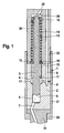
- FIG. 1 shows a pressure booster for a fuel injector, having a one-piece pressure booster body.
- a pressure booster 1 for a fuel injector has a one-piece pressure booster body 2 on. In this a piston 3 is added. The piston 3 is over a pressure change operable within a differential pressure chamber 4. The piston points at his lower end of a compression surface 6, which acts on a compression space 5. From the compression chamber 5, a high-pressure inlet 7 extends into a in FIG. 1 not shown nozzle space.
- the high pressure bore 8 is the control line of the Pressure Translator 1 dar.
- the end face of the piston 3 is designated by reference numeral 10, while a the differential pressure space 4 assigning annular surface of the piston 3 identified by reference numeral 11 is.
- the differential pressure chamber 4 has an annular below the connecting lines 9 configured bottom surface 17 on.
- a piston pin 12 is formed, which as a Compression spring designed spring element 14 is enclosed.
- the spring element 14 is supported on the one hand on a piston pin 12 formed on the stop 13 and on the other hand a transfer ring 15 from.
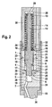
- the pressure booster 1 is divided into two parts Pressure translator body is added.
- the piston 3 of the pressure booster 1 according to the representation in FIG. 2 also acts with its annular surface 11 on the differential pressure chamber 4, which is connected to the high-pressure bore 8 serving as a control line is.
- Below the differential pressure chamber 4 is the compression chamber 5, in which when retracting the compression surface 6 of the piston 3, the fuel increased Pressure levels is awarded.
- a in FIG. 2 extends Unillustrated high-pressure inlet to a nozzle chamber, which is an injection valve member surrounds.
- a transfer ring 15 At the end 10 of the piston 3 is a transfer ring 15 at.
- the transmission ring 15 is acted upon by a spring element designed as a compression spring 14 which is supported on the stop 13.
- the stopper 13 is at the upper end of the piston 3 of the Pressure Translator 1 connected piston pin 12 is formed.
- the the piston pin 12th surrounding compression spring 13 serves as a pressure adjusting element for the piston 3 in its initial position, as soon as in the differential pressure chamber 4, the compression chamber 5 and a working space 28 equal pressure is applied.
- the differential pressure chamber 4 Analogous to the representation of the pressure booster according to FIG 1, the differential pressure chamber 4 has an annularly configured bottom surface 17.
- the spring element designed as a compression spring 14 Transfer ring 15 at.
- the pressure translator body in a first pressure booster housing part 18 and a second Pressure intensifier body part 19 divided.
- the first pressure booster housing part 18 and the second pressure booster housing part 19 are adjacent to each other along a dividing joint 20.
- In the region of the parting line 20 of the first pressure booster housing part 18 and the second Druckbergersetzergekoruse learners 19 is designed as a connecting groove 27 connecting line 9 between the differential pressure chamber 4 and serving as a control line High-pressure bore 8 is formed.
- the groove-shaped connection 27 between the Differential pressure chamber 4 and serving as a control line high-pressure bore 8 can both at the lower end of the first housing part 18 and at the upper end of the second Housing parts 19, i. lie in the region of the dividing joint 20.
- the integrally formed piston 3 of the pressure booster 1 centers the first housing part 18 and the second housing part 19 of the multi-part pressure booster body to each other.
- each housing part 18 and 19 at a region of the piston 3 of the pressure booster 1 is present occurs in a first guide portion 21 of the upper portion of the piston 3 and in a second guide portion 22, which is formed in the second housing part 19, increased wear. This can be prevented by that the two pressure booster housing parts 18 and 19 with the axial force 24 are applied.
- a static mounting force for example can be applied by a nozzle lock nut 31.
- a nozzle lock nut 31 About the nozzle lock nut 31 are an injector body 30 in which the working space 28 is formed and a nozzle body 34 screwed together at the combustion chamber end of the fuel injector.
- the nozzle retaining nut 31 encloses the two Druckschreibsetzergekorusemaschine 18 and 19.
- the two pressure booster housing parts 18 and 19 braced against each other in the axial direction. This can be on the one hand a seal of the first pressure booster housing part 18 against the injector body 30 and a seal of the second pressure booster housing part 19 against the Achieve nozzle body 34.
- the working space 28 via a high-pressure inlet 29 is pressurized system pressure.
- the working space 28 serves at the same time for recording both the piston pin 12 and arranged on this compression spring 14.
- Figure 2 is the acting on the upper end face of the first pressure booster housing part 18 Axial force indicated by the arrows 24.
- Due to the centering of the intensifier housing parts 18 and 19 on a one-piece trained piston 3 of the pressure booster 1 and the same with an in axial direction acting force 24 may be a self-adjusting cross-compression in the compression direction 23 of the first pressure booster housing part 18 and second pressure booster housing part 19 for the radial expansion of the first guide portion 21 and the second guide portion 22 are used. This will be in the first guide section 21 and in the second guide section 22 guide gaps 25 generated. hereby becomes jamming of the piston 3 in the first guide portion 21 as well as in the second Guide section 22 effectively prevented; furthermore, it is simplified in a not inconsiderable manner Measures the manufacture of the split intensifier body with first intensifier housing part 18 and second pressure booster housing part 19. With the erfmdungswash proposed Solution is a significant voltage reduction at a pressure booster 1 with a one-piece piston 3 achieve.
- a lateral surface of the compression space. 5 in the second housing part 19 is denoted by reference numeral 26.
- the compression chamber 5 is within the second pressure booster housing part 19 through the compression surface 6 at the lower end of the piston 3 of the pressure booster 1 acted upon.
- the differential pressure chamber 4 is through the annular configured bottom surface 17 and the piston 3 formed on the annular surface 11 limited. Another boundary is that shown within the first housing part 18 encircling wall.
- the axial force 24 is over the nozzle lock nut 31 shown schematically in Figure 2 in the two pressure booster housing parts 18 and 19 initiated.
- the nozzle body 34 is enclosed by a shoulder 33 formed on the nozzle retaining nut 31, so that the Parts 30 and 34, the Druckschreibsetzergephaseusemaschine 18 and 19 when tightening the nozzle lock nut 31 brace against each other with a corresponding mounting torque.
- the in axial Direction acting axial force 24 can also be initiated by a plurality of expansion screws, so that a compression in the transverse direction of the two strained against each other in this way Pressure booster housing parts 18 and 19 takes place.
- bracing variants is a leak-free connection of the first pressure booster housing part 18 with the second pressure booster housing part 19 in the region of Dividing gap 20 reached.
Landscapes
- Engineering & Computer Science (AREA)
- Chemical & Material Sciences (AREA)
- Combustion & Propulsion (AREA)
- Mechanical Engineering (AREA)
- General Engineering & Computer Science (AREA)
- Manufacturing & Machinery (AREA)
- Fuel-Injection Apparatus (AREA)
Applications Claiming Priority (2)
| Application Number | Priority Date | Filing Date | Title |
|---|---|---|---|
| DE2003146575 DE10346575A1 (de) | 2003-10-07 | 2003-10-07 | Druckübersetzer für Kraftstoffinjektoren mit zentriertem mehrteiligem Druckübersetzerkörper |
| DE10346575 | 2003-10-07 |
Publications (2)
| Publication Number | Publication Date |
|---|---|
| EP1522720A2 true EP1522720A2 (fr) | 2005-04-13 |
| EP1522720A3 EP1522720A3 (fr) | 2008-04-30 |
Family
ID=34306308
Family Applications (1)
| Application Number | Title | Priority Date | Filing Date |
|---|---|---|---|
| EP04103877A Withdrawn EP1522720A3 (fr) | 2003-10-07 | 2004-08-12 | Amplificateur de pression pour injecteur de carburant comprenant un boitier en plusieurs parties |
Country Status (2)
| Country | Link |
|---|---|
| EP (1) | EP1522720A3 (fr) |
| DE (1) | DE10346575A1 (fr) |
Family Cites Families (4)
| Publication number | Priority date | Publication date | Assignee | Title |
|---|---|---|---|---|
| US6161770A (en) * | 1994-06-06 | 2000-12-19 | Sturman; Oded E. | Hydraulically driven springless fuel injector |
| US5865156A (en) * | 1997-12-03 | 1999-02-02 | Caterpillar Inc. | Actuator which uses fluctuating pressure from an oil pump that powers a hydraulically actuated fuel injector |
| KR20010111310A (ko) * | 1999-04-19 | 2001-12-17 | 인터내셔널 엔진 인터렉츄얼 프로퍼티 캄파니, 엘엘씨 | 연료압력 지연 실린더 |
| DE10355041A1 (de) * | 2003-11-25 | 2005-06-23 | Robert Bosch Gmbh | Druckübersetzer mit Führungseinsatz für einen Kraftstoffinjektor |
-
2003
- 2003-10-07 DE DE2003146575 patent/DE10346575A1/de not_active Withdrawn
-
2004
- 2004-08-12 EP EP04103877A patent/EP1522720A3/fr not_active Withdrawn
Also Published As
| Publication number | Publication date |
|---|---|
| EP1522720A3 (fr) | 2008-04-30 |
| DE10346575A1 (de) | 2005-05-04 |
Similar Documents
| Publication | Publication Date | Title |
|---|---|---|
| WO2008083881A1 (fr) | Injecteur pour injecter du carburant dans les chambres de combustion des moteurs à combustion interne | |
| EP1613856A1 (fr) | Injecteur de carburant comportant un transmetteur de pression commande par une soupape asservie | |
| DE19706591A1 (de) | Druckventil | |
| EP1554488B1 (fr) | Dispositif d'injection de carburant a pression multipliee, pourvu d'une conduite de commande interne | |
| EP1688611B1 (fr) | Injecteur de carburant à commande de pointeau directe pour un moteur à combustion interne | |
| WO2001014710A1 (fr) | Systeme d'injection de carburant pour un moteur a combustion interne | |
| EP1117922B1 (fr) | Injecteur a rampe commune | |
| WO2010009932A1 (fr) | Injecteur de combustible | |
| EP1382838A2 (fr) | Injecteur de carburant | |
| DE10217594A1 (de) | Brennstoffeinspritzventil | |
| DE19945785B4 (de) | Kraftstoffeinspritzsystem für Brennkraftmaschinen und Verfahren zum Einspritzen von Kraftstoff in den Brennraum einer Brennkraftmaschine | |
| DE102006017034B4 (de) | Piezo-Aktor, Verfahren zum Herstellen eines Piezo-Aktors und Einspritzsystem mit einem solchen | |
| EP1714026B1 (fr) | Soupape d'injection de carburant | |
| EP1522720A2 (fr) | Amplificateur de pression pour injecteur de carburant comprenant un boitier en plusieurs parties | |
| DE10353641B4 (de) | Brennstoffeinspritzventil | |
| EP1519035A1 (fr) | Soupape d'injection de combustible | |
| EP1642023B1 (fr) | Raccordement pour espaces haute pression d'injecteurs de carburant | |
| EP2539575B1 (fr) | Injecteur de carburant avec un ensemble aiguille d'injecteur | |
| EP1377745B1 (fr) | Procede pour actionner une unite pompe-ajutage et unite pompe-ajutage correspondante | |
| DE10315489B3 (de) | Kraftstoffinjektor mit Druckübersetzer und in ein Düsenmodul integriertem Dämpfungskolben | |
| WO2003027485A1 (fr) | Systeme d'injection de carburant dote d'un injecteur hydrauliquement deconnecte de la conduite d'alimentation | |
| DE102009026567A1 (de) | Kraftstoffinjektor mit Druckverstärkerkolben | |
| DE102007016866A1 (de) | Hochdichter Kraftstoffinjektor | |
| DE10241657A1 (de) | Hochdruckleitung für Kraftstoffeinspitzsysteme von Brennkraftmaschinen | |
| DE102004044462A1 (de) | Steuerventil für einen Injektor |
Legal Events
| Date | Code | Title | Description |
|---|---|---|---|
| PUAI | Public reference made under article 153(3) epc to a published international application that has entered the european phase |
Free format text: ORIGINAL CODE: 0009012 |
|
| AK | Designated contracting states |
Kind code of ref document: A2 Designated state(s): AT BE BG CH CY CZ DE DK EE ES FI FR GB GR HU IE IT LI LU MC NL PL PT RO SE SI SK TR |
|
| AX | Request for extension of the european patent |
Extension state: AL HR LT LV MK |
|
| PUAL | Search report despatched |
Free format text: ORIGINAL CODE: 0009013 |
|
| AK | Designated contracting states |
Kind code of ref document: A3 Designated state(s): AT BE BG CH CY CZ DE DK EE ES FI FR GB GR HU IE IT LI LU MC NL PL PT RO SE SI SK TR |
|
| AX | Request for extension of the european patent |
Extension state: AL HR LT LV MK |
|
| AKX | Designation fees paid | ||
| STAA | Information on the status of an ep patent application or granted ep patent |
Free format text: STATUS: THE APPLICATION IS DEEMED TO BE WITHDRAWN |
|
| 18D | Application deemed to be withdrawn |
Effective date: 20081031 |
|
| REG | Reference to a national code |
Ref country code: DE Ref legal event code: 8566 |