EP1522720A2 - Pressure amplifier for fuel injector with centered multiple housing parts - Google Patents
Pressure amplifier for fuel injector with centered multiple housing parts Download PDFInfo
- Publication number
- EP1522720A2 EP1522720A2 EP04103877A EP04103877A EP1522720A2 EP 1522720 A2 EP1522720 A2 EP 1522720A2 EP 04103877 A EP04103877 A EP 04103877A EP 04103877 A EP04103877 A EP 04103877A EP 1522720 A2 EP1522720 A2 EP 1522720A2
- Authority
- EP
- European Patent Office
- Prior art keywords
- pressure
- piston
- pressure booster
- booster
- housing parts
- Prior art date
- Legal status (The legal status is an assumption and is not a legal conclusion. Google has not performed a legal analysis and makes no representation as to the accuracy of the status listed.)
- Withdrawn
Links
Images
Classifications
-
- F—MECHANICAL ENGINEERING; LIGHTING; HEATING; WEAPONS; BLASTING
- F02—COMBUSTION ENGINES; HOT-GAS OR COMBUSTION-PRODUCT ENGINE PLANTS
- F02M—SUPPLYING COMBUSTION ENGINES IN GENERAL WITH COMBUSTIBLE MIXTURES OR CONSTITUENTS THEREOF
- F02M61/00—Fuel-injectors not provided for in groups F02M39/00 - F02M57/00 or F02M67/00
- F02M61/16—Details not provided for in, or of interest apart from, the apparatus of groups F02M61/02 - F02M61/14
- F02M61/168—Assembling; Disassembling; Manufacturing; Adjusting
-
- F—MECHANICAL ENGINEERING; LIGHTING; HEATING; WEAPONS; BLASTING
- F02—COMBUSTION ENGINES; HOT-GAS OR COMBUSTION-PRODUCT ENGINE PLANTS
- F02M—SUPPLYING COMBUSTION ENGINES IN GENERAL WITH COMBUSTIBLE MIXTURES OR CONSTITUENTS THEREOF
- F02M57/00—Fuel-injectors combined or associated with other devices
- F02M57/02—Injectors structurally combined with fuel-injection pumps
- F02M57/022—Injectors structurally combined with fuel-injection pumps characterised by the pump drive
- F02M57/025—Injectors structurally combined with fuel-injection pumps characterised by the pump drive hydraulic, e.g. with pressure amplification
- F02M57/026—Construction details of pressure amplifiers, e.g. fuel passages or check valves arranged in the intensifier piston or head, particular diameter relationships, stop members, arrangement of ports or conduits
-
- F—MECHANICAL ENGINEERING; LIGHTING; HEATING; WEAPONS; BLASTING
- F02—COMBUSTION ENGINES; HOT-GAS OR COMBUSTION-PRODUCT ENGINE PLANTS
- F02M—SUPPLYING COMBUSTION ENGINES IN GENERAL WITH COMBUSTIBLE MIXTURES OR CONSTITUENTS THEREOF
- F02M61/00—Fuel-injectors not provided for in groups F02M39/00 - F02M57/00 or F02M67/00
- F02M61/16—Details not provided for in, or of interest apart from, the apparatus of groups F02M61/02 - F02M61/14
- F02M61/167—Means for compensating clearance or thermal expansion
Definitions
- High-pressure accumulator injection systems For injecting fuel into direct-injection internal combustion engines stroke-controlled high-pressure accumulator injection systems (common rail) are used. These Fuel injection systems are characterized in that the injection pressure to load and speed of the internal combustion engine can be adjusted. To reduce the Emissions and to achieve high specific performance is a high injection pressure required. Because the achievable pressure level in high pressure fuel pumps for strength reasons is limited, can further increase pressure in high-pressure injection systems (Common rail) can be achieved via pressure booster on fuel injectors.
- Common rail high-pressure injection systems
- DE 101 23 913 discloses a fuel injection device for internal combustion engines with a fuel injector, which can be supplied by a high-pressure fuel source. Between the Fuel injector and the high-pressure fuel source is a movable pressure booster piston connected pressure booster connected. Their pressure booster piston separates a connectable to the high-pressure fuel source space of a High pressure chamber connected to the fuel injector. By filling a backspace the pressure booster device with fuel or by emptying the rear space of Fuel, the fuel pressure in the high-pressure chamber can be varied.
- the fuel injector has a movable closing piston for opening and closing of injection openings on, wherein the closing piston protrudes into a closing pressure space.
- the closing piston is at fuel pressure to achieve a closing direction on the closing piston Acting force acted upon.
- the closing pressure chamber and the rear space are through formed a common closing pressure-back space, wherein all portions of the Closing pressure return chamber permanently connected to each other for the exchange of fuel are.
- It is a pressure chamber for supplying fuel to the injection port and to Actuation of the closing piston provided with a force acting in the opening direction.
- the high-pressure chamber communicates with the high-pressure fuel source in such a way, that in the high-pressure chamber, apart from pressure oscillations, constantly at least the fuel pressure can abut the high-pressure fuel source.
- the pressure room and the high pressure room are formed by a common injection space, the partial areas permanently connected to each other for the exchange of fuel.
- the booster piston with the housing parts by a radial expansion i.e. a transverse compression of the housing parts are significantly reduced.
- the guide sections expand due to their Axialkraftbeaufschlagung in the radial direction on, so that a surface contact between the lateral surface of the piston and the guide sections is avoided.
- the axial force for example, via a nozzle lock nut apply, with which the injector body and a nozzle body, between which the Pressure booster housing parts are arranged, are braced against each other.
- the axial force For example, it can also be arranged over several expansion screws evenly arranged on the injector be initiated.
- the axial force thus acts on both DruckGermansetzergekorusemaschine. Because of this static Assembly force, the two pressure booster housing parts are always sealing against each other biased. The axial force leads to a radial expansion of the two along a shock and a parting line adjacent housing parts of the pressure booster. Increased wear is thus avoided.
- a groove-shaped Connection between a control line and the pressure booster operating differential pressure chamber be formed in the region of the dividing joint, at which the two housing parts the body of the pressure booster lie against each other.
- the groove-shaped compound can either in the first Housing part of the pressure booster or in the second housing part of the pressure booster be formed.
- the use of a two-part can be Pressure intensifier piston bypass that in previous applications to a due the higher tolerances led to different injection quantities, whereby the injection course was falsified and considerable tolerances in each case in the combustion chamber The amount of fuel injected by the internal combustion engine has occurred.
- the invention proposed solution allows a significant reduction in voltage within a critical area at the pressure intensifier, namely in the connection area between the differential pressure chamber and the control line.
- the inventively proposed Solution also contributes to a lifetime increase of the intensifier and a Simplification of the production of pressure intensifiers controlled via their differential pressure chamber at.
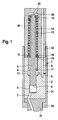
- FIG. 1 shows a pressure booster for a fuel injector, having a one-piece pressure booster body.
- a pressure booster 1 for a fuel injector has a one-piece pressure booster body 2 on. In this a piston 3 is added. The piston 3 is over a pressure change operable within a differential pressure chamber 4. The piston points at his lower end of a compression surface 6, which acts on a compression space 5. From the compression chamber 5, a high-pressure inlet 7 extends into a in FIG. 1 not shown nozzle space.
- the high pressure bore 8 is the control line of the Pressure Translator 1 dar.
- the end face of the piston 3 is designated by reference numeral 10, while a the differential pressure space 4 assigning annular surface of the piston 3 identified by reference numeral 11 is.
- the differential pressure chamber 4 has an annular below the connecting lines 9 configured bottom surface 17 on.
- a piston pin 12 is formed, which as a Compression spring designed spring element 14 is enclosed.
- the spring element 14 is supported on the one hand on a piston pin 12 formed on the stop 13 and on the other hand a transfer ring 15 from.
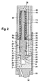
- the pressure booster 1 is divided into two parts Pressure translator body is added.
- the piston 3 of the pressure booster 1 according to the representation in FIG. 2 also acts with its annular surface 11 on the differential pressure chamber 4, which is connected to the high-pressure bore 8 serving as a control line is.
- Below the differential pressure chamber 4 is the compression chamber 5, in which when retracting the compression surface 6 of the piston 3, the fuel increased Pressure levels is awarded.
- a in FIG. 2 extends Unillustrated high-pressure inlet to a nozzle chamber, which is an injection valve member surrounds.
- a transfer ring 15 At the end 10 of the piston 3 is a transfer ring 15 at.
- the transmission ring 15 is acted upon by a spring element designed as a compression spring 14 which is supported on the stop 13.
- the stopper 13 is at the upper end of the piston 3 of the Pressure Translator 1 connected piston pin 12 is formed.
- the the piston pin 12th surrounding compression spring 13 serves as a pressure adjusting element for the piston 3 in its initial position, as soon as in the differential pressure chamber 4, the compression chamber 5 and a working space 28 equal pressure is applied.
- the differential pressure chamber 4 Analogous to the representation of the pressure booster according to FIG 1, the differential pressure chamber 4 has an annularly configured bottom surface 17.
- the spring element designed as a compression spring 14 Transfer ring 15 at.
- the pressure translator body in a first pressure booster housing part 18 and a second Pressure intensifier body part 19 divided.
- the first pressure booster housing part 18 and the second pressure booster housing part 19 are adjacent to each other along a dividing joint 20.
- In the region of the parting line 20 of the first pressure booster housing part 18 and the second Druckbergersetzergekoruse learners 19 is designed as a connecting groove 27 connecting line 9 between the differential pressure chamber 4 and serving as a control line High-pressure bore 8 is formed.
- the groove-shaped connection 27 between the Differential pressure chamber 4 and serving as a control line high-pressure bore 8 can both at the lower end of the first housing part 18 and at the upper end of the second Housing parts 19, i. lie in the region of the dividing joint 20.
- the integrally formed piston 3 of the pressure booster 1 centers the first housing part 18 and the second housing part 19 of the multi-part pressure booster body to each other.
- each housing part 18 and 19 at a region of the piston 3 of the pressure booster 1 is present occurs in a first guide portion 21 of the upper portion of the piston 3 and in a second guide portion 22, which is formed in the second housing part 19, increased wear. This can be prevented by that the two pressure booster housing parts 18 and 19 with the axial force 24 are applied.
- a static mounting force for example can be applied by a nozzle lock nut 31.
- a nozzle lock nut 31 About the nozzle lock nut 31 are an injector body 30 in which the working space 28 is formed and a nozzle body 34 screwed together at the combustion chamber end of the fuel injector.
- the nozzle retaining nut 31 encloses the two Druckschreibsetzergekorusemaschine 18 and 19.
- the two pressure booster housing parts 18 and 19 braced against each other in the axial direction. This can be on the one hand a seal of the first pressure booster housing part 18 against the injector body 30 and a seal of the second pressure booster housing part 19 against the Achieve nozzle body 34.
- the working space 28 via a high-pressure inlet 29 is pressurized system pressure.
- the working space 28 serves at the same time for recording both the piston pin 12 and arranged on this compression spring 14.
- Figure 2 is the acting on the upper end face of the first pressure booster housing part 18 Axial force indicated by the arrows 24.
- Due to the centering of the intensifier housing parts 18 and 19 on a one-piece trained piston 3 of the pressure booster 1 and the same with an in axial direction acting force 24 may be a self-adjusting cross-compression in the compression direction 23 of the first pressure booster housing part 18 and second pressure booster housing part 19 for the radial expansion of the first guide portion 21 and the second guide portion 22 are used. This will be in the first guide section 21 and in the second guide section 22 guide gaps 25 generated. hereby becomes jamming of the piston 3 in the first guide portion 21 as well as in the second Guide section 22 effectively prevented; furthermore, it is simplified in a not inconsiderable manner Measures the manufacture of the split intensifier body with first intensifier housing part 18 and second pressure booster housing part 19. With the erfmdungswash proposed Solution is a significant voltage reduction at a pressure booster 1 with a one-piece piston 3 achieve.
- a lateral surface of the compression space. 5 in the second housing part 19 is denoted by reference numeral 26.
- the compression chamber 5 is within the second pressure booster housing part 19 through the compression surface 6 at the lower end of the piston 3 of the pressure booster 1 acted upon.
- the differential pressure chamber 4 is through the annular configured bottom surface 17 and the piston 3 formed on the annular surface 11 limited. Another boundary is that shown within the first housing part 18 encircling wall.
- the axial force 24 is over the nozzle lock nut 31 shown schematically in Figure 2 in the two pressure booster housing parts 18 and 19 initiated.
- the nozzle body 34 is enclosed by a shoulder 33 formed on the nozzle retaining nut 31, so that the Parts 30 and 34, the Druckschreibsetzergephaseusemaschine 18 and 19 when tightening the nozzle lock nut 31 brace against each other with a corresponding mounting torque.
- the in axial Direction acting axial force 24 can also be initiated by a plurality of expansion screws, so that a compression in the transverse direction of the two strained against each other in this way Pressure booster housing parts 18 and 19 takes place.
- bracing variants is a leak-free connection of the first pressure booster housing part 18 with the second pressure booster housing part 19 in the region of Dividing gap 20 reached.
Landscapes
- Engineering & Computer Science (AREA)
- Chemical & Material Sciences (AREA)
- Combustion & Propulsion (AREA)
- Mechanical Engineering (AREA)
- General Engineering & Computer Science (AREA)
- Manufacturing & Machinery (AREA)
- Fuel-Injection Apparatus (AREA)
Abstract
Description
Zum Einspritzen von Kraftstoff in direkt einspritzende Verbrennungskraftmaschinen können hubgesteuerte Hochdruckspeichereinspritzsysteme (Common-Rail) eingesetzt werden. Diese Kraftstoffeinspritzsysteme zeichnen sich dadurch aus, dass der Einspritzdruck an Last und Drehzahl der Verbrennungskraftmaschine angepasst werden kann. Zur Reduzierung der Emissionen und zur Erzielung hoher spezifischer Leistungen ist ein hoher Einspritzdruck erforderlich. Da das erreichbare Druckniveau in Hochdruckkraftstoffpumpen aus Festigkeitsgründen begrenzt ist, kann eine weitere Drucksteigerung bei Hochdruckeinspritzsystemen (Common-Rail) über Druckübersetzer an Kraftstoffinjektoren erzielt werden.For injecting fuel into direct-injection internal combustion engines stroke-controlled high-pressure accumulator injection systems (common rail) are used. These Fuel injection systems are characterized in that the injection pressure to load and speed of the internal combustion engine can be adjusted. To reduce the Emissions and to achieve high specific performance is a high injection pressure required. Because the achievable pressure level in high pressure fuel pumps for strength reasons is limited, can further increase pressure in high-pressure injection systems (Common rail) can be achieved via pressure booster on fuel injectors.
DE 101 23 913 offenbart eine Kraftstoffeinspritzeinrichtung für Brennkraftmaschinen mit einem von einer Kraftstoffhochdruckquelle versorgbaren Kraftstoffinjektor. Zwischen dem Kraftstoffinjektor und der Kraftstoffhochdruckquelle ist eine einen beweglichen Druckübersetzerkolben aufweisende Druckübersetzungseinrichtung geschaltet. Deren Druckübersetzerkolben trennt einen an die Kraftstoffhochdruckquelle anschließbaren Raum von einem mit dem Kraftstoffinjektor verbundenen Hochdruckraum. Durch Befüllen eines Rückraumes der Druckübersetzungseinrichtung mit Kraftstoff bzw. durch Entleeren des Rückraumes von Kraftstoff kann der Kraftstoffdruck im Hochdruckraum variiert werden. Der Kraftstoffmjektor weist einen beweglichen Schließkolben zum Öffnen und Verschließen von Einspritzöffnungen auf, wobei der Schließkolben in einen Schließdruckraum hineinragt. Der Schließkolben ist mit Kraftstoffdruck zur Erzielung einer Schließrichtung auf den Schließkolben wirkenden Kraft beaufschlagbar. Der Schließdruckraum und der Rückraum werden durch einen gemeinsamen Schließdruck-Rückraum gebildet, wobei sämtliche Teilbereiche des Schließdruck-Rückraumes permanent zum Austausch von Kraftstoff miteinander verbunden sind. Es ist ein Druckraum zum Versorgen der Einspritzöffnung mit Kraftstoff und zum Beaufschlagen des Schließkolbens mit einer in Öffnungsrichtung wirkenden Kraft vorgesehen. Der Hochdruckraum steht derart mit der Kraftstoffhochdruckquelle in Verbindung, dass im Hochdruckraum, abgesehen von Druckschwingungen, ständig zumindest der Kraftstoffdruck der Kraftstoffhochdruckquelle anliegen kann. Der Druckraum und der Hochdruckraum werden durch einen gemeinsamen Einspritzraum gebildet, dessen Teilbereiche permanent zum Austausch von Kraftstoff miteinander verbunden sind.DE 101 23 913 discloses a fuel injection device for internal combustion engines with a fuel injector, which can be supplied by a high-pressure fuel source. Between the Fuel injector and the high-pressure fuel source is a movable pressure booster piston connected pressure booster connected. Their pressure booster piston separates a connectable to the high-pressure fuel source space of a High pressure chamber connected to the fuel injector. By filling a backspace the pressure booster device with fuel or by emptying the rear space of Fuel, the fuel pressure in the high-pressure chamber can be varied. The fuel injector has a movable closing piston for opening and closing of injection openings on, wherein the closing piston protrudes into a closing pressure space. The closing piston is at fuel pressure to achieve a closing direction on the closing piston Acting force acted upon. The closing pressure chamber and the rear space are through formed a common closing pressure-back space, wherein all portions of the Closing pressure return chamber permanently connected to each other for the exchange of fuel are. It is a pressure chamber for supplying fuel to the injection port and to Actuation of the closing piston provided with a force acting in the opening direction. The high-pressure chamber communicates with the high-pressure fuel source in such a way, that in the high-pressure chamber, apart from pressure oscillations, constantly at least the fuel pressure can abut the high-pressure fuel source. The pressure room and the high pressure room are formed by a common injection space, the partial areas permanently connected to each other for the exchange of fuel.
Durch die erfindungsgemäß vorgeschlagene Lösung können die an einem Druckübersetzerkörper eines Kraftstoffinjektors auftretenden Spannungen erheblich reduziert werden. Die Spannungen treten insbesondere im Bereich zwischen dem Differenzdruckraum des Druckübersetzers, über den dieser betätigt wird und einer Steuerleitung aufgrund des anliegenden hydraulischen Druckes auf. Durch die erfindungsgemäß vorgeschlagene Lösung kann der Körper des Druckübersetzers in zwei Gehäuseteile geteilt werden, die mittels eines einteilig ausgebildeten Druckübersetzerkolbens zentriert werden.By the solution proposed by the invention can on a pressure booster body a fuel injector occurring voltages are significantly reduced. The Tensions occur in particular in the region between the differential pressure chamber of the pressure booster, over which this is actuated and a control line due to the adjacent hydraulic pressure on. By inventively proposed solution of the Body of the intensifier to be divided into two housing parts by means of a one-piece trained pressure intensifier piston centered.
Durch Erzeugung einer in axiale Richtung wirkenden Kraft kann der Verschleiss in den Führungsabschnitten des Übersetzerkolbens mit den Gehäuseteilen durch eine radiale Aufweitung, d.h. eine Querstauchung der Gehäuseteile erheblich herabgesetzt werden. Die Führungsabschnitte weiten sich aufgrund ihrer Axialkraftbeaufschlagung in radiale Richtung auf, so dass ein Flächenkontakt zwischen der Mantelfläche des Kolbens und den Führungsabschnitten vermieden wird. Die Axialkraft, lässt sich beispielsweise über eine Düsenspannmutter aufbringen, mit welcher der Injektorkörper und ein Düsenkörper, zwischen denen die Druckübersetzergehäuseteile angeordnet sind, gegeneinander verspannt sind. Die Axialkraft kann beispielsweise auch über mehrere gleichmäßig am Injektor angeordnete Dehnungsschrauben eingeleitet werden.By generating a force acting in the axial direction of the wear in the guide sections the booster piston with the housing parts by a radial expansion, i.e. a transverse compression of the housing parts are significantly reduced. The guide sections expand due to their Axialkraftbeaufschlagung in the radial direction on, so that a surface contact between the lateral surface of the piston and the guide sections is avoided. The axial force, for example, via a nozzle lock nut apply, with which the injector body and a nozzle body, between which the Pressure booster housing parts are arranged, are braced against each other. The axial force For example, it can also be arranged over several expansion screws evenly arranged on the injector be initiated.
Die Axialkraft wirkt somit auf beiden Druckübersetzergehäuseteile. Aufgrund dieser statischen Montagekraft sind die beiden Druckübersetzergehäuseteile stets dichtend gegeneinander vorgespannt. Die Axialkraft führt zu einer radialen Aufweitung der beiden entlang einer Stoß- und einer Trennungsfuge aneinander anliegenden Gehäuseteile des Druckübersetzers. Erhöhter Verschleiß wird somit vermieden.The axial force thus acts on both Druckübersetzergehäuseteile. Because of this static Assembly force, the two pressure booster housing parts are always sealing against each other biased. The axial force leads to a radial expansion of the two along a shock and a parting line adjacent housing parts of the pressure booster. Increased wear is thus avoided.
In besonders vorteilhafter Weise kann im Bereich der Teilungsfuge, an der die beiden Gehäuseteile des Körpers des Druckübersetzers aneinander liegen, eine nutförmig ausgebildete Verbindung zwischen einer Steuerleitung und dem den Druckübersetzers betätigenden Differenzdruckraum ausgebildet werden. Die nutförmige Verbindung kann entweder im ersten Gehäuseteil des Druckübersetzers oder auch im zweiten Gehäuseteil des Druckübersetzers ausgebildet werden.In a particularly advantageous manner, in the region of the dividing joint, at which the two housing parts the body of the pressure booster lie against each other, a groove-shaped Connection between a control line and the pressure booster operating differential pressure chamber be formed. The groove-shaped compound can either in the first Housing part of the pressure booster or in the second housing part of the pressure booster be formed.
Durch die erfindungsgemäß vorgeschlagene Lösung lässt sich der Einsatz eines zweigeteilten Druckübersetzerkolbens umgehen, der bei bisherigen Anwendungen zu einer aufgrund der höheren Toleranzen zu unterschiedlichen Einspritzmengen führte, wodurch der Einspritzverlauf verfälscht wurde und erhebliche Toleranzen bei der jeweils in den Brennraum der Verbrennungskraftmaschine eingespritzten Kraftstoffmenge aufgetreten sind. Die erfindungsgemäß vorgeschlagene Lösung erlaubt eine erhebliche Spannungsreduzierung innerhalb eines kritischen Bereiches am Druckübersetzer, nämlich im Verbindungsbereich zwischen dem Differenzdruckraum und der Steuerleitung. Die erfindungsgemäß vorgeschlagene Lösung trägt ferner zu einer Lebensdauererhöhung des Druckübersetzers sowie zu einer Vereinfachung der Fertigung von über ihren Differenzdruckraum angesteuerten Druckübersetzem bei.By the proposed solution according to the invention, the use of a two-part can be Pressure intensifier piston bypass that in previous applications to a due the higher tolerances led to different injection quantities, whereby the injection course was falsified and considerable tolerances in each case in the combustion chamber The amount of fuel injected by the internal combustion engine has occurred. The invention proposed solution allows a significant reduction in voltage within a critical area at the pressure intensifier, namely in the connection area between the differential pressure chamber and the control line. The inventively proposed Solution also contributes to a lifetime increase of the intensifier and a Simplification of the production of pressure intensifiers controlled via their differential pressure chamber at.
Anhand der Zeichnung wird die Erfmdung nachstehend eingehender beschrieben.The invention will be described in more detail below with reference to the drawing.
Es zeigt:
Figur 1- einen aus dem Stand der Technik bekannten Druckübersetzer mit einteiligem Druckübersetzerkörper und
Figur 2- einen erfindungsgemäß vorgeschlagenen Druckübersetzer mit geteiltem Druckübersetzergehäuse.
- FIG. 1
- a known from the prior art pressure booster with one-piece pressure booster body and
- FIG. 2
- a pressure intensifier according to the invention with a shared pressure booster housing.
Aus der Darstellung gemäß Figur 1 geht ein Druckübersetzer für ein Kraftstoffinjektor vor, der einen einteiligen Druckübersetzerkörper aufweist.The illustration according to FIG. 1 shows a pressure booster for a fuel injector, having a one-piece pressure booster body.
Ein Druckübersetzer 1 für einen Kraftstoffinjektor weist einen einteiligen Druckübersetzerkörper
2 auf. In diesem ist ein Kolben 3 aufgenommen. Der Kolben 3 ist über eine Druckänderung
innerhalb eines Differenzdruckraumes 4 betätigbar. Der Kolben weist an seinem
unteren Ende eine Kompressionsfläche 6 auf, die einen Kompressionsraum 5 beaufschlagt.
Vom Kompressionsraum 5 aus erstreckt sich ein Hochdruckzulauf 7 in einen in Figur 1
nicht dargestellten Düsenraum. A
Der Differenzdruckraum 4, über welchen der Druckübersetzer 1 betätigbar ist, ist über eine
Verbindungsleitung 9 mit einer den einteiligen Druckübersetzerkörper 2 durchsetzenden
Hochdruckbohrung 8 verbunden. Die Hochdruckbohrung 8 stellt die Steuerleitung des
Druckübersetzers 1 dar.The
Die Stirnseite des Kolbens 3 ist mit Bezugszeichen 10 bezeichnet, während eine dem Differenzdruckraum
4 zuweisende Ringfläche des Kolbens 3 durch Bezugszeichen 11 identifiziert
ist. Der Differenzdruckraum 4 weist unterhalb der Verbindungsleitungen 9 eine ringförmig
konfigurierte Bodenfläche 17 auf.The end face of the
Am oberen Ende des Kolbens 3 ist ein Kolbenzapfen 12 ausgebildet, welcher von einem als
Druckfeder ausgelegten Federelement 14 umschlossen ist. Das Federelement 14 stützt sich
einerseits an einem am Kolbenzapfen 12 ausgebildeten Anschlag 13 und andererseits an
einem Übertragungsring 15 ab.At the upper end of the
Bei Druckentlastung des Differenzdruckraumes 4 erfolgt ein Einfahren der Kompressionsfläche
6 des Kolbens 3 in den Kompressionsraum 5. Während der Einfahrbewegung des
Kolbens 3 in den Kompressionsraum 5 wird die Druckfeder 14 zusammengedrückt und
setzt auf dem Übertragungsring 15 auf. Aus dem Kompressionsraum 5 wird dabei aufgrund
des erhöhten Druckes ein Kraftstoffvolumen in den Hochdruckzulauf 7 zu einem in Figur 1
nicht dargestellten Düsenraum abgesteuert. Das aus dem Kompressionsraum 5 entweichende
Kraftstoffvolumen weist ein entsprechend dem Druckübersetzungsverhältnis des Druckübersetzers
erhöhtes Druckniveau auf.When pressure relief of the
Aus der Darstellung gemäß Figur 2 ist ein Schnitt durch einen erfmdungsgemäß vorgeschlagenen Druckübersetzers mit geteiltem Druckübersetzergehäuse entnehmbar.From the illustration according to FIG. 2, a section through an inventive proposed Pressure intensifier with split pressure booster housing removable.
Aus der Darstellung gemäß Figur 2 geht hervor, dass der Druckübersetzer 1 in einem geteilten
Druckübersetzerkörper aufgenommen ist. Der Kolben 3 des Druckübersetzers 1 gemäß
der Darstellung in Figur 2 beaufschlagt mit seiner Ringfläche 11 ebenfalls den Differenzdruckraum
4, der mit der als Steuerleitung dienenden Hochdruckbohrung 8 verbunden
ist. Unterhalb des Differenzdruckraumes 4 befmdet sich der Kompressionsraum 5, in welchem
bei Einfahren der Kompressionsfläche 6 des Kolbens 3 dem Kraftstoff ein erhöhtes
Druckniveaus verliehen wird. Vom Kompressionsraum 5 aus erstreckt sich ein in Figur 2
nicht dargestellter Hochdruckzulauf zu einem Düsenraum, welcher ein Einspritzventilglied
umgibt.From the illustration according to FIG. 2, it can be seen that the
An der Stirnseite 10 des Kolbens 3 liegt ein Übertragungsring 15 an. Der Übertragungsring
15 ist von einem als Druckfeder 14 ausgebildeten Federelement beaufschlagt, welches sich
am Anschlag 13 abstützt. Der Anschlag 13 ist am oberen Ende eines mit dem Kolben 3 des
Druckübersetzers 1 verbundenen Kolbenzapfen 12 ausgebildet. Die den Kolbenzapfen 12
umgebende Druckfeder 13 dient als Druckstellelement für den Kolben 3 in seiner Ausgangslage,
sobald im Differenzdruckraum 4, dem Kompressionsraum 5 und einem Arbeitsraum
28 gleicher Druck anliegt. Analog zur Darstellung des Druckübersetzers gemäß Figur
1 weist der Differenzdruckraum 4 eine ringförmig konfigurierte Bodenfläche 17 auf. An
einer Auflagefläche 16 liegt der über das als Druckfeder 14 ausgebildete Federelement beaufschlagte
Übertragungsring 15 an.At the
In der erfmdungsgemäß vorgeschlagenen Ausführungsvariante eines Druckübersetzers 1 ist
dessen Druckübersetzerkörper in ein erstes Druckübersetzergehäuseteil 18 sowie ein zweites
Druckübersetzerkörperteil 19 geteilt. Das erste Druckübersetzergehäuseteil 18 und das
zweite Druckübersetzergehäuseteil 19 liegen entlang einer Teilungsfuge 20 aneinander an.
Im Bereich der Teilungsfuge 20 des ersten Druckübersetzergehäuseteiles 18 und des zweiten
Druckübersetzergehäuseteiles 19 ist eine als Verbindungsnut 27 beschaffene Verbindungsleitung
9 zwischen dem Differenzdruckraum 4 und der als Steuerleitung dienenden
Hochdruckbohrung 8 ausgebildet. Die nutförmig ausgebildete Verbindung 27 zwischen dem
Differenzdruckraum 4 und der als Steuerleitung dienenden Hochdruckbohrung 8 kann sowohl
am unteren Ende des ersten Gehäuseteiles 18 als auch am oberen Ende des zweiten
Gehäuseteiles 19, d.h. im Bereich der Teilungsfuge 20 liegen.In the variant of a
Der einteilig ausgebildete Kolben 3 des Druckübersetzers 1 zentriert das erste Gehäuseteil
18 und das zweite Gehäuseteil 19 des mehrteilig ausgebildeten Druckübersetzerkörpers
zueinander. Da bei der Montage des Druckübersetzers 1 jedes Gehäuseteil 18 bzw. 19 an
einem Bereich des Kolbens 3 des Druckübersetzers 1 anliegt, tritt in einem ersten Führungsabschnitt
21 des oberen Bereiches des Kolbens 3 sowie in einem zweiten Führungsabschnitt
22, welcher im zweiten Gehäuseteil 19 ausgebildet ist, erhöhter Verschleiß auf. Dies kann
dadurch unterbunden werden, dass die beiden Druckübersetzergehäuseteile 18 bzw. 19 mit
der Axialkraft 24 beaufschlagt werden.The integrally formed
Bei der Axialkraft 24 handelt es sich um eine statische Montagekraft, die beispielsweise
durch eine Düsenspannmutter 31 aufgebracht werden kann. Über die Düsenspannmutter 31
sind ein Injektorkörper 30 in dem der Arbeitsraum 28 ausgebildet ist und ein Düsenkörper
34 am brennraumseitigen Ende des Kraftstoffinjektors miteinander verschraubt. Die Düsenspannmutter
31 umschließt die beiden Druckübersetzergehäuseteile 18 bzw. 19. Bei Verschrauben
der Düsenspannmutter 31 am Injektorkörper 30 werden die beiden Druckübersetzergehäuseteile
18 und 19 in axiale Richtung gegeneinander verspannt. Damit lässt sich
einerseits eine Abdichtung des ersten Druckübersetzergehäuseteiles 18 gegen den Injektorkörper
30 sowie eine Abdichtung des zweiten Druckübersetzergehäuseteiles 19 gegen den
Düsenkörper 34 erzielen. Darüber hinauswird durch die Beaufschlagung der beiden Druckübersetzergehäuseteile
18 bzw. 19 mit der Axialkraft 24 und dem radialen Aufweiten eine
verschleißarme Führung des Kolbens 3 innerhalb des ersten Führungsabschnittes 21 sowie
innerhalb des zweiten Führungsabschnittes 22 erzielt. Die Stauchung der beiden Druckübersetzergehäuseteile
18 bzw. 19 in Stauchungsrichtung 23, d.h. in radiale Richtung, bewirkt
einen Führungsspalt 25.In the
Der Vollständigkeit halber sei erwähnt, dass der Arbeitsraum 28 über einen Hochdruckzulauf
29 mit Systemdruck beaufschlagt wird. Der Arbeitsraum 28 dient gleichzeitig zur Aufnahme
sowohl des Kolbenzapfens 12 als auch der an diesen angeordneten Druckfeder 14. In
Figur 2 ist die auf die obere Stirnseite des ersten Druckübersetzergehäuseteiles 18 einwirkende
Axialkraft durch die Pfeile 24 angedeutet.For completeness, it should be mentioned that the working
Aufgrund der in Figur 2 in die eingezeichnete Richtung wirkenden Axialkraft 24 verformt
sich sowohl das erste Gehäuseteil 18 als auch das zweite Gehäuseteil 19 derart, dass sich die
Führungsabschnitte 21 bzw. 22 in eine Stauchungsrichtung 23, d.h. radial zur Achse des
Kolbens 3 aufweiten. Dadurch wird eine Berührung zwischen den Mantelflächen des Kolbens
3 des Druckübersetzers 1 und dem ersten Führungsabschnitt 21 des ersten Druckübersetzergehäuseteiles
18 als auch dem zweiten Führungsabschnitt 22 des zweiten Druckübersetzergehäuseteiles
19 unterbunden. Somit bewegt sich der Kolben 3 des Druckübersetzers
1 bei Druckänderung im Differenzdruckraum 4, d.h. bei Druckerhöhung bzw. bei Druckabsenkung
in diesem annäherend reibungsfrei sowohl im ersten Führungsabschnitt 21 des ersten
Druckübersetzergehäuseteiles 18 als auch im zweiten Führungsabschnitt 22 des zweiten
Druckübersetzergehäuseteiles 19. Aufgrund der in radiale Richtung 23 wirkenden Aufweitung
der Druckübersetzergehäuseteile 18 bzw. 19 wird ein erhöhter Verschleiss des Kolbens
3 bei Betätigung des Druckübersetzers 1 vermieden. Bei Beauschlagung der an der Teilungsfuge
20 aneinanderliegende Druckübersetzergehäuseteile 18 bzw. 19 durch die Axialkraft
24 treten am ersten Führungsabschnitt 21 bzw. am zweiten Führungsabschnitt 22
Spalte 25 auf, die eine verschleißfreie Bewegung des Druckübersetzerkolbens 3 innerhalb
der Druckübersetzergehäuseteile 18 und 19 ermöglichen.Due to the
Aufgrund der Zentrierung der Druckübersetzergehäuseteile 18 bzw. 19 an einem einteilig
ausgebildeten Kolben 3 des Druckübersetzers 1 und Beaufschlagung desselben mit einer in
axiale Richtung wirkenden Kraft 24 kann eine sich einstellende Querstauchung in Stauchungsrichtung
23 des ersten Druckübersetzergehäuseteiles 18 bzw. zweiten Druckübersetzergehäuseteiles
19 zur radialen Aufweitung des ersten Führungsabschnittes 21 als auch des
zweiten Führungsabschnittes 22 genutzt werden. Dadurch werden im ersten Führungsabschnitt
21 bzw. im zweiten Führungsabschnitt 22 Führungsspalte 25 erzeugt. Hierdurch
wird ein Verklemmen des Kolbens 3 im ersten Führungsabschnitt 21 als auch im zweiten
Führungsabschnitt 22 wirksam verhindert; ferner vereinfacht sich in nicht unerheblichem
Maße die Herstellung des geteilten Druckübersetzerkörpers mit erstem Druckübersetzergehäuseteil
18 und zweitem Druckübersetzergehäuseteil 19. Mit der erfmdungsgemäß vorgeschlagenen
Lösung lässt sich eine erhebliche Spannungsreduzierung an einem Druckübersetzer
1 mit einem einteiligen Kolben 3 erzielen.Due to the centering of the
Der Vollständigkeit halber sei erwähnt, dass eine Mantelfläche des Kompressionsraumes 5
im zweiten Gehäuseteil 19 mit Bezugszeichen 26 gekennzeichnet ist. Analog zur Darstellung
des Druckübersetzers gemäß Figur 1 wird der Kompressionsraum 5 innerhalb des
zweiten Druckübersetzergehäuseteiles 19 durch die Kompressionsfläche 6 am unteren Ende
des Kolbens 3 des Druckübersetzers 1 beaufschlagt. Der Differenzdruckraum 4 ist durch die
ringförmig konfigurierte Bodenfläche 17 sowie die am Kolben 3 ausgebildeten Ringfläche
11 begrenzt. Eine weitere Umgrenzung stellt die innerhalb des ersten Gehäuseteiles 18 dargestellte
umlaufende Wand dar.For completeness, it should be mentioned that a lateral surface of the compression space. 5
in the
Die Axialkraft 24 wird über die in Figur 2 schematisch dargestellte Düsenspannmutter 31 in
die beiden Druckübersetzergehäuseteile 18 bzw. 19 eingeleitet. Der Düsenkörper 34 wird
von einer an der Düsenspannmutter 31 ausgebildeten Schulter 33 umschlossen, so dass die
Teile 30 und 34 die Druckübersetzergehäuseteile 18 und 19 beim Anziehen der Düsenspannmutter
31 mit einem entsprechenden Montagedrehmoment gegeneinander verspannen.
Anstelle der in Figur 2 schematisch dargestellten Düsenspannmutter 31 kann die in axiale
Richtung wirkende Axialkraft 24 auch durch mehrere Dehnschrauben eingeleitet werden, so
dass eine Stauchung in Querrichtung der beiden auf diese Weise gegeneinander verspannten
Druckübersetzergehäuseteile 18 und 19 erfolgt.The
Durch diese Verspannungsvarianten wird eine leckagefreie Verbindung des ersten Druckübersetzergehäuseteiles
18 mit dem zweiten Druckübersetzergehäuseteil 19 im Bereich der
Teilungsfuge 20 erreicht. By these bracing variants is a leak-free connection of the first pressure
- 11
- Druckübersetzer eines KraftstoffinjektorsPressure intensifier of a fuel injector
- 22
- einteiliger Druckübersetzerkörperone-piece pressure intensifier body
- 33
- Kolbenpiston
- 44
- Differenzdruckraum (Rückraum)Differential pressure chamber (backspace)
- 55
- Kompressionsraumcompression chamber
- 66
- Kompressionsflächecompression surface
- 77
- Hochdruckzulauf (zum Düsenraum)High pressure inlet (to the nozzle chamber)
- 88th
- Hochdruckbohrung (Steuerleitung)High pressure bore (control line)
- 99
- Verbindungsleitungconnecting line
- 1010
- Stirnseite KolbenFront side pistons
- 1111
- Ringfläche KolbenRing surface piston
- 1212
- Kolbenzapfenpiston pin
- 1313
- Anschlagattack
- 1414
- Druckfedercompression spring
- 1515
- Übertragungsringtransmission ring
- 1616
- Auflageflächebearing surface
- 1717
- Bodenground
- 1818
- erstes Druckübersetzergehäuseteilfirst intensifier housing part
- 1919
- zweites Druckübersetzergehäuseteilsecond intensifier housing part
- 2020
- Teilungsfugedividing
- 2121
- erster Führungsabschnittfirst guide section
- 2222
- zweiter Führungsabschnittsecond guide section
- 2323
- StauchungsrichtungCompression direction
- 2424
- Axialkraftaxial force
- 2525
- Führungsspaltguide gap
- 2626
- Mantelfläche KompressionsraumLateral surface compression space
- 2727
- Verbindungsnutcommunicating
- 2828
- Arbeitsraumworking space
- 2929
- HochdruckzulaufHigh-pressure inlet
- 3030
- Injektorkörperinjector
- 3131
- DüsenspannmutterNozzle clamping nut
- 3232
- Gewindethread
- 3333
- Schultershoulder
- 3434
- Düsenkörpernozzle body
Claims (9)
Applications Claiming Priority (2)
| Application Number | Priority Date | Filing Date | Title |
|---|---|---|---|
| DE10346575 | 2003-10-07 | ||
| DE2003146575 DE10346575A1 (en) | 2003-10-07 | 2003-10-07 | Pressure intensifier for fuel injectors with centered multi-part intensifier body |
Publications (2)
| Publication Number | Publication Date |
|---|---|
| EP1522720A2 true EP1522720A2 (en) | 2005-04-13 |
| EP1522720A3 EP1522720A3 (en) | 2008-04-30 |
Family
ID=34306308
Family Applications (1)
| Application Number | Title | Priority Date | Filing Date |
|---|---|---|---|
| EP04103877A Withdrawn EP1522720A3 (en) | 2003-10-07 | 2004-08-12 | Pressure amplifier for fuel injector with centered multiple housing parts |
Country Status (2)
| Country | Link |
|---|---|
| EP (1) | EP1522720A3 (en) |
| DE (1) | DE10346575A1 (en) |
Family Cites Families (4)
| Publication number | Priority date | Publication date | Assignee | Title |
|---|---|---|---|---|
| US6161770A (en) * | 1994-06-06 | 2000-12-19 | Sturman; Oded E. | Hydraulically driven springless fuel injector |
| US5865156A (en) * | 1997-12-03 | 1999-02-02 | Caterpillar Inc. | Actuator which uses fluctuating pressure from an oil pump that powers a hydraulically actuated fuel injector |
| US6408829B1 (en) * | 1999-04-19 | 2002-06-25 | International Engine Intellectual Property Company, L.L.C. | Fuel pressure delay cylinder |
| DE10355041A1 (en) * | 2003-11-25 | 2005-06-23 | Robert Bosch Gmbh | Pressure intensifier with guide insert for a fuel injector |
-
2003
- 2003-10-07 DE DE2003146575 patent/DE10346575A1/en not_active Withdrawn
-
2004
- 2004-08-12 EP EP04103877A patent/EP1522720A3/en not_active Withdrawn
Also Published As
| Publication number | Publication date |
|---|---|
| EP1522720A3 (en) | 2008-04-30 |
| DE10346575A1 (en) | 2005-05-04 |
Similar Documents
| Publication | Publication Date | Title |
|---|---|---|
| WO2008083881A1 (en) | Injector for injecting fuel into combustion chambers of internal combustion engines | |
| EP1613856A1 (en) | Fuel injector provided with a pressure transmitter controlled by a servo valve | |
| DE19706591A1 (en) | Pressure valve | |
| EP1554488B1 (en) | Pressure-boosted fuel injection device comprising an internal control line | |
| EP1688611B1 (en) | Fuel injector with direct needle control for an internal combustion engine | |
| WO2001014710A1 (en) | Fuel injection system for an internal combustion engine | |
| EP1117922B1 (en) | Common rail injector | |
| DE10229415A1 (en) | Device for damping the needle stroke on pressure-controlled fuel injectors | |
| WO2004046540A1 (en) | Injector with a directly-actuated compound nozzle needle for fuel injection in an internal combustion engine | |
| WO2010009932A1 (en) | Fuel injector | |
| EP1382838A2 (en) | Fuel injector | |
| DE10217594A1 (en) | Fuel injection valve for IC engines has throttle gap formed by Laser/erosion drilling, and positioned separate from guide gaps, for cheaper fabrication of gaps | |
| DE19945785B4 (en) | Fuel injection system for internal combustion engines and method for injecting fuel into the combustion chamber of an internal combustion engine | |
| DE19949527A1 (en) | Injector for a fuel injection system for internal combustion engines with a nozzle needle protruding into the valve control chamber | |
| DE102006017034B4 (en) | Piezo actuator, method for producing a piezo actuator and injection system with such | |
| EP2539575B1 (en) | Fuel injector with a nozzle needle assembly | |
| EP1714026B1 (en) | Fuel-injection valve | |
| DE10353641B4 (en) | Fuel injector | |
| EP1519035A1 (en) | Fuel injection valve | |
| EP1642023B1 (en) | Connection for high-pressure spaces of fuel injectors | |
| EP1377745B1 (en) | Method for operating a pump-nozzle unit and a corresponding pump-nozzle unit | |
| DE10315489B3 (en) | Fuel injector for use in internal combustion engine has integrated damping piston and has pressure increasing system connected to fuel pressure reservoir | |
| WO2003027485A1 (en) | Fuel injection system with injector hydraulically decoupled from the supply | |
| DE102009026567A1 (en) | Fuel injector with pressure intensifier piston | |
| DE102007016866A1 (en) | High-density fuel injector, has throttle plate surrounded by retaining body of fuel injector, where luggage compartment and control chamber stand in hydraulic connection with each other over throttle plate |
Legal Events
| Date | Code | Title | Description |
|---|---|---|---|
| PUAI | Public reference made under article 153(3) epc to a published international application that has entered the european phase |
Free format text: ORIGINAL CODE: 0009012 |
|
| AK | Designated contracting states |
Kind code of ref document: A2 Designated state(s): AT BE BG CH CY CZ DE DK EE ES FI FR GB GR HU IE IT LI LU MC NL PL PT RO SE SI SK TR |
|
| AX | Request for extension of the european patent |
Extension state: AL HR LT LV MK |
|
| PUAL | Search report despatched |
Free format text: ORIGINAL CODE: 0009013 |
|
| AK | Designated contracting states |
Kind code of ref document: A3 Designated state(s): AT BE BG CH CY CZ DE DK EE ES FI FR GB GR HU IE IT LI LU MC NL PL PT RO SE SI SK TR |
|
| AX | Request for extension of the european patent |
Extension state: AL HR LT LV MK |
|
| AKX | Designation fees paid | ||
| STAA | Information on the status of an ep patent application or granted ep patent |
Free format text: STATUS: THE APPLICATION IS DEEMED TO BE WITHDRAWN |
|
| 18D | Application deemed to be withdrawn |
Effective date: 20081031 |
|
| REG | Reference to a national code |
Ref country code: DE Ref legal event code: 8566 |