EP1522696A2 - Compresseur axial avec injection d'eau pour turbine à gaz - Google Patents
Compresseur axial avec injection d'eau pour turbine à gaz Download PDFInfo
- Publication number
- EP1522696A2 EP1522696A2 EP04104153A EP04104153A EP1522696A2 EP 1522696 A2 EP1522696 A2 EP 1522696A2 EP 04104153 A EP04104153 A EP 04104153A EP 04104153 A EP04104153 A EP 04104153A EP 1522696 A2 EP1522696 A2 EP 1522696A2
- Authority
- EP
- European Patent Office
- Prior art keywords
- compressor
- blades
- stages
- water
- changed
- Prior art date
- Legal status (The legal status is an assumption and is not a legal conclusion. Google has not performed a legal analysis and makes no representation as to the accuracy of the status listed.)
- Withdrawn
Links
Images


Classifications
-
- F—MECHANICAL ENGINEERING; LIGHTING; HEATING; WEAPONS; BLASTING
- F02—COMBUSTION ENGINES; HOT-GAS OR COMBUSTION-PRODUCT ENGINE PLANTS
- F02C—GAS-TURBINE PLANTS; AIR INTAKES FOR JET-PROPULSION PLANTS; CONTROLLING FUEL SUPPLY IN AIR-BREATHING JET-PROPULSION PLANTS
- F02C7/00—Features, components parts, details or accessories, not provided for in, or of interest apart form groups F02C1/00 - F02C6/00; Air intakes for jet-propulsion plants
- F02C7/12—Cooling of plants
- F02C7/14—Cooling of plants of fluids in the plant, e.g. lubricant or fuel
- F02C7/141—Cooling of plants of fluids in the plant, e.g. lubricant or fuel of working fluid
- F02C7/143—Cooling of plants of fluids in the plant, e.g. lubricant or fuel of working fluid before or between the compressor stages
- F02C7/1435—Cooling of plants of fluids in the plant, e.g. lubricant or fuel of working fluid before or between the compressor stages by water injection
-
- F—MECHANICAL ENGINEERING; LIGHTING; HEATING; WEAPONS; BLASTING
- F01—MACHINES OR ENGINES IN GENERAL; ENGINE PLANTS IN GENERAL; STEAM ENGINES
- F01D—NON-POSITIVE DISPLACEMENT MACHINES OR ENGINES, e.g. STEAM TURBINES
- F01D5/00—Blades; Blade-carrying members; Heating, heat-insulating, cooling or antivibration means on the blades or the members
- F01D5/12—Blades
- F01D5/14—Form or construction
- F01D5/141—Shape, i.e. outer, aerodynamic form
- F01D5/142—Shape, i.e. outer, aerodynamic form of the blades of successive rotor or stator blade-rows
-
- F—MECHANICAL ENGINEERING; LIGHTING; HEATING; WEAPONS; BLASTING
- F04—POSITIVE - DISPLACEMENT MACHINES FOR LIQUIDS; PUMPS FOR LIQUIDS OR ELASTIC FLUIDS
- F04D—NON-POSITIVE-DISPLACEMENT PUMPS
- F04D29/00—Details, component parts, or accessories
- F04D29/40—Casings; Connections of working fluid
- F04D29/52—Casings; Connections of working fluid for axial pumps
- F04D29/54—Fluid-guiding means, e.g. diffusers
- F04D29/56—Fluid-guiding means, e.g. diffusers adjustable
- F04D29/563—Fluid-guiding means, e.g. diffusers adjustable specially adapted for elastic fluid pumps
-
- F—MECHANICAL ENGINEERING; LIGHTING; HEATING; WEAPONS; BLASTING
- F04—POSITIVE - DISPLACEMENT MACHINES FOR LIQUIDS; PUMPS FOR LIQUIDS OR ELASTIC FLUIDS
- F04D—NON-POSITIVE-DISPLACEMENT PUMPS
- F04D29/00—Details, component parts, or accessories
- F04D29/70—Suction grids; Strainers; Dust separation; Cleaning
- F04D29/701—Suction grids; Strainers; Dust separation; Cleaning especially adapted for elastic fluid pumps
- F04D29/705—Adding liquids
-
- F—MECHANICAL ENGINEERING; LIGHTING; HEATING; WEAPONS; BLASTING
- F05—INDEXING SCHEMES RELATING TO ENGINES OR PUMPS IN VARIOUS SUBCLASSES OF CLASSES F01-F04
- F05D—INDEXING SCHEME FOR ASPECTS RELATING TO NON-POSITIVE-DISPLACEMENT MACHINES OR ENGINES, GAS-TURBINES OR JET-PROPULSION PLANTS
- F05D2260/00—Function
- F05D2260/20—Heat transfer, e.g. cooling
- F05D2260/212—Heat transfer, e.g. cooling by water injection
Definitions
- the present invention relates to the field of gas turbines. It concerns an axial compressor according to the preamble of claim 1.
- the object is solved by the entirety of the features of claim 1.
- the essence of the invention is that of the injected water conditional changes in the flow velocities of the Compressor flowing medium through a targeted change in geometry to largely compensate for the blades.
- This geometry change is it is possible to defy water injection in the optimum region of the curve remain dependent on the loss in a compressor stage of Angle of the relative flow velocity of the inflowing into the stage Medium describes.
- a Preferred embodiment of the invention is therefore characterized in that at the stages where the axial flow velocity of the medium through the injection of water increases, the noses of the blades to one open position are changed, and that at the stages where the axial Flow rate of the medium by injecting the water decreases, the noses of the blades to a more closed position are changed.
- the axial compressor is a middle stage in which the injection of water is the axial Flow rate only insignificantly influenced in the in Flow direction before the middle stage arranged steps the noses of the Shovels are changed to a more open position, and that at the in Flow direction after the middle stage arranged steps the noses of the Blades are changed to a more closed position.
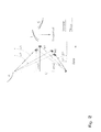
- the invention is based on an axial compressor 10, as shown schematically in FIG. 6 is reproduced.
- the axial compressor 10 has a rotor 11 which is concentric is arranged rotatably in a stator 13 about a rotor axis 12.
- the stages ST1, .., ST5 include each a wreath of rotor blades or blades R and a wreath of stator vanes or vanes S.
- Through the axial compressor flows from Compressor input 14 to the compressor output 15 a medium, in particular Air being compressed. If the compressor is part of a gas turbine, the compressed air as combustion air in the burner of the gas turbine.
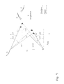
- the rotating rotor blades R shape that through the Compressor flowing medium to a flow velocity.
- the Stator blades S cause a subsequent deflection before that too Compressing medium enters the next stage.
- the rotor blades R have a linear rotor speed U.
- the absolute flow velocities of the medium at the entrance and at the exit of the stage are c1 and c2 respectively.
- she enclose an angle ⁇ 1 or ⁇ 2 with the axial direction.
- the relative Flow velocities of the medium with respect to the rotor blades R at the entrance and exit of the stage are w1 and w2, respectively.
- the evaporation of the injected water leads to the front Steps to increase the axial flow velocity cm1 or cm2 (Transition from solid vector to dotted vector). Associated with this is a change (reduction) in the angle ⁇ 1.
Landscapes
- Engineering & Computer Science (AREA)
- Mechanical Engineering (AREA)
- General Engineering & Computer Science (AREA)
- Chemical & Material Sciences (AREA)
- Combustion & Propulsion (AREA)
- Physics & Mathematics (AREA)
- Fluid Mechanics (AREA)
- Structures Of Non-Positive Displacement Pumps (AREA)
Applications Claiming Priority (2)
| Application Number | Priority Date | Filing Date | Title |
|---|---|---|---|
| DE10342097 | 2003-09-10 | ||
| DE10342097A DE10342097A1 (de) | 2003-09-10 | 2003-09-10 | Axialkompressor |
Publications (1)
| Publication Number | Publication Date |
|---|---|
| EP1522696A2 true EP1522696A2 (fr) | 2005-04-13 |
Family
ID=34258588
Family Applications (1)
| Application Number | Title | Priority Date | Filing Date |
|---|---|---|---|
| EP04104153A Withdrawn EP1522696A2 (fr) | 2003-09-10 | 2004-08-31 | Compresseur axial avec injection d'eau pour turbine à gaz |
Country Status (4)
| Country | Link |
|---|---|
| US (1) | US7165935B2 (fr) |
| EP (1) | EP1522696A2 (fr) |
| CA (1) | CA2480136A1 (fr) |
| DE (1) | DE10342097A1 (fr) |
Cited By (2)
| Publication number | Priority date | Publication date | Assignee | Title |
|---|---|---|---|---|
| DE102008003333A1 (de) | 2008-01-07 | 2009-07-09 | Dirk Landau | Brennkraftmaschine zur Erzeugung von Wärme und elektrischer Energie, ausgeführt als stromerzeugende Heizung |
| EP2551486A1 (fr) * | 2011-07-25 | 2013-01-30 | Alstom Technology Ltd | Procédé permettant d'injecter de l'eau dans un compresseur axial à étapes multiples d'une turbine à gaz |
Families Citing this family (5)
| Publication number | Priority date | Publication date | Assignee | Title |
|---|---|---|---|---|
| WO2007017498A1 (fr) * | 2005-08-10 | 2007-02-15 | Alstom Technology Ltd | Procede de conception aerodynamique d'un compresseur d'une turbomachine |
| US8475117B2 (en) * | 2009-11-10 | 2013-07-02 | General Electric Company | Gas turbine compressor and method of operation |
| US8567177B1 (en) | 2012-11-30 | 2013-10-29 | Yoganeck, LLC | Gas turbine engine system with water recycling feature |
| CN113982988B (zh) * | 2020-04-16 | 2023-04-25 | 李伟 | 离心式轴流向涡轮及新型喷气发动机模式和运行方法 |
| CN114458632B (zh) * | 2020-11-09 | 2023-08-04 | 中国航发上海商用航空发动机制造有限责任公司 | 一种用于压气机的可调静子叶片的机械限位结构 |
Family Cites Families (7)
| Publication number | Priority date | Publication date | Assignee | Title |
|---|---|---|---|---|
| DE844632C (de) * | 1948-10-02 | 1952-07-24 | Siemens Ag | Vielstufiger Axialverdichter, dessen Reaktionsgrad sich stufenweise aendert |
| US4295784A (en) * | 1979-09-26 | 1981-10-20 | United Technologies Corporation | Variable stator |
| DE4407829A1 (de) * | 1994-03-09 | 1995-09-14 | Abb Patent Gmbh | Verfahren zur quasiisothermen Verdichtung von Luft |
| JP2877098B2 (ja) * | 1995-12-28 | 1999-03-31 | 株式会社日立製作所 | ガスタービン,コンバインドサイクルプラント及び圧縮機 |
| US5867977A (en) * | 1996-05-14 | 1999-02-09 | The Dow Chemical Company | Method and apparatus for achieving power augmentation in gas turbines via wet compression |
| US6398518B1 (en) * | 2000-03-29 | 2002-06-04 | Watson Cogeneration Company | Method and apparatus for increasing the efficiency of a multi-stage compressor |
| GB2382848A (en) * | 2001-12-06 | 2003-06-11 | Alstom | Gas turbine wet compression |
-
2003
- 2003-09-10 DE DE10342097A patent/DE10342097A1/de not_active Ceased
-
2004
- 2004-08-31 EP EP04104153A patent/EP1522696A2/fr not_active Withdrawn
- 2004-09-01 US US10/931,065 patent/US7165935B2/en not_active Expired - Fee Related
- 2004-09-03 CA CA002480136A patent/CA2480136A1/fr not_active Abandoned
Cited By (4)
| Publication number | Priority date | Publication date | Assignee | Title |
|---|---|---|---|---|
| DE102008003333A1 (de) | 2008-01-07 | 2009-07-09 | Dirk Landau | Brennkraftmaschine zur Erzeugung von Wärme und elektrischer Energie, ausgeführt als stromerzeugende Heizung |
| EP2551486A1 (fr) * | 2011-07-25 | 2013-01-30 | Alstom Technology Ltd | Procédé permettant d'injecter de l'eau dans un compresseur axial à étapes multiples d'une turbine à gaz |
| CH705323A1 (de) * | 2011-07-25 | 2013-01-31 | Alstom Technology Ltd | Verfahren zum Einspritzen von Wasser in einen mehrstufigen Axialverdichter einer Gasturbine. |
| US10480404B2 (en) | 2011-07-25 | 2019-11-19 | Ansaldo Energia Switzerland AG | Method for injecting water into a multistage axial compressor of a gas turbine |
Also Published As
| Publication number | Publication date |
|---|---|
| US7165935B2 (en) | 2007-01-23 |
| US20050063819A1 (en) | 2005-03-24 |
| CA2480136A1 (fr) | 2005-03-10 |
| DE10342097A1 (de) | 2005-04-07 |
Similar Documents
| Publication | Publication Date | Title |
|---|---|---|
| DE60133629T2 (de) | Verfahren zum betrieb einer gasturbine mit verstellbaren leitschaufeln | |
| DE69915283T2 (de) | Kreiselrad für turbomaschinen | |
| EP1113145B1 (fr) | Aube pour turbine a gaz avec section de mesure sur le bord de fuite | |
| DE69831109T2 (de) | Kühlluftzufuhrsystem für die Schaufeln einer Gasturbine | |
| DE60018817T2 (de) | Gekühlte Gasturbinenschaufel | |
| DE69105837T2 (de) | Gekühlte Turbinenschaufel. | |
| EP2835522B2 (fr) | Dispositif et procédé de soufflage d'air comprimé dans une turbine | |
| DE2262883A1 (de) | Zentrifugalpumpe mit variablem diffusor | |
| DE1817430A1 (de) | Regenerativkompressor | |
| DE3514354A1 (de) | Gekuehlte gasturbine mit lastabhaengig regelbarer kuehlluftmenge | |
| DE2031612A1 (de) | Vielstufiger Axialkompressor mit einem Luftableitsystem als Zwischen stufe | |
| DE2454054A1 (de) | Innentriebwerk bzw. gasgenerator fuer gasturbinentriebwerke | |
| DE102007017826B4 (de) | Abgasturbolader | |
| DE102008044505B4 (de) | Radialverdichter | |
| EP3290644A1 (fr) | Turbine a gaz | |
| EP3009683A1 (fr) | Système et procédé pour prélèvement d'air de compresseur d'un propulseur | |
| EP0118769A2 (fr) | Turbine à plusieurs étages avec bandages extérieurs | |
| EP1522696A2 (fr) | Compresseur axial avec injection d'eau pour turbine à gaz | |
| WO2006048401A1 (fr) | Etage de turbine optimise dans une installation de turbines et procede de conception | |
| WO2013107489A1 (fr) | Procédé et dispositif pour stabiliser un flux de compresseur | |
| DE3132134A1 (de) | Verfahren und vorrichtung zur verminderung des stroemungsquerschnitts des auspuffgases im leitkranz eines turbokompressors fuer einen verbrennungsmotor | |
| DE102014115963A1 (de) | Rotor-Kühlung | |
| DE102008051980A1 (de) | Luftversorgungsvorrichtung für eine Brennstoffzelle | |
| EP1632650B1 (fr) | Turbine à vapeur | |
| DE102010035393A1 (de) | Turbine und Verfahren zum Betrieb einer Turbine für ein CAES-System |
Legal Events
| Date | Code | Title | Description |
|---|---|---|---|
| PUAI | Public reference made under article 153(3) epc to a published international application that has entered the european phase |
Free format text: ORIGINAL CODE: 0009012 |
|
| AK | Designated contracting states |
Kind code of ref document: A2 Designated state(s): AT BE BG CH CY CZ DE DK EE ES FI FR GB GR HU IE IT LI LU MC NL PL PT RO SE SI SK TR |
|
| AX | Request for extension of the european patent |
Extension state: AL HR LT LV MK |
|
| STAA | Information on the status of an ep patent application or granted ep patent |
Free format text: STATUS: THE APPLICATION IS DEEMED TO BE WITHDRAWN |
|
| 18D | Application deemed to be withdrawn |
Effective date: 20130301 |