EP1522696A2 - Gas turbine axial compressor with water injection - Google Patents
Gas turbine axial compressor with water injection Download PDFInfo
- Publication number
- EP1522696A2 EP1522696A2 EP04104153A EP04104153A EP1522696A2 EP 1522696 A2 EP1522696 A2 EP 1522696A2 EP 04104153 A EP04104153 A EP 04104153A EP 04104153 A EP04104153 A EP 04104153A EP 1522696 A2 EP1522696 A2 EP 1522696A2
- Authority
- EP
- European Patent Office
- Prior art keywords
- compressor
- blades
- stages
- water
- changed
- Prior art date
- Legal status (The legal status is an assumption and is not a legal conclusion. Google has not performed a legal analysis and makes no representation as to the accuracy of the status listed.)
- Withdrawn
Links
Images


Classifications
-
- F—MECHANICAL ENGINEERING; LIGHTING; HEATING; WEAPONS; BLASTING
- F02—COMBUSTION ENGINES; HOT-GAS OR COMBUSTION-PRODUCT ENGINE PLANTS
- F02C—GAS-TURBINE PLANTS; AIR INTAKES FOR JET-PROPULSION PLANTS; CONTROLLING FUEL SUPPLY IN AIR-BREATHING JET-PROPULSION PLANTS
- F02C7/00—Features, components parts, details or accessories, not provided for in, or of interest apart form groups F02C1/00 - F02C6/00; Air intakes for jet-propulsion plants
- F02C7/12—Cooling of plants
- F02C7/14—Cooling of plants of fluids in the plant, e.g. lubricant or fuel
- F02C7/141—Cooling of plants of fluids in the plant, e.g. lubricant or fuel of working fluid
- F02C7/143—Cooling of plants of fluids in the plant, e.g. lubricant or fuel of working fluid before or between the compressor stages
- F02C7/1435—Cooling of plants of fluids in the plant, e.g. lubricant or fuel of working fluid before or between the compressor stages by water injection
-
- F—MECHANICAL ENGINEERING; LIGHTING; HEATING; WEAPONS; BLASTING
- F01—MACHINES OR ENGINES IN GENERAL; ENGINE PLANTS IN GENERAL; STEAM ENGINES
- F01D—NON-POSITIVE DISPLACEMENT MACHINES OR ENGINES, e.g. STEAM TURBINES
- F01D5/00—Blades; Blade-carrying members; Heating, heat-insulating, cooling or antivibration means on the blades or the members
- F01D5/12—Blades
- F01D5/14—Form or construction
- F01D5/141—Shape, i.e. outer, aerodynamic form
- F01D5/142—Shape, i.e. outer, aerodynamic form of the blades of successive rotor or stator blade-rows
-
- F—MECHANICAL ENGINEERING; LIGHTING; HEATING; WEAPONS; BLASTING
- F04—POSITIVE - DISPLACEMENT MACHINES FOR LIQUIDS; PUMPS FOR LIQUIDS OR ELASTIC FLUIDS
- F04D—NON-POSITIVE-DISPLACEMENT PUMPS
- F04D29/00—Details, component parts, or accessories
- F04D29/40—Casings; Connections of working fluid
- F04D29/52—Casings; Connections of working fluid for axial pumps
- F04D29/54—Fluid-guiding means, e.g. diffusers
- F04D29/56—Fluid-guiding means, e.g. diffusers adjustable
- F04D29/563—Fluid-guiding means, e.g. diffusers adjustable specially adapted for elastic fluid pumps
-
- F—MECHANICAL ENGINEERING; LIGHTING; HEATING; WEAPONS; BLASTING
- F04—POSITIVE - DISPLACEMENT MACHINES FOR LIQUIDS; PUMPS FOR LIQUIDS OR ELASTIC FLUIDS
- F04D—NON-POSITIVE-DISPLACEMENT PUMPS
- F04D29/00—Details, component parts, or accessories
- F04D29/70—Suction grids; Strainers; Dust separation; Cleaning
- F04D29/701—Suction grids; Strainers; Dust separation; Cleaning especially adapted for elastic fluid pumps
- F04D29/705—Adding liquids
-
- F—MECHANICAL ENGINEERING; LIGHTING; HEATING; WEAPONS; BLASTING
- F05—INDEXING SCHEMES RELATING TO ENGINES OR PUMPS IN VARIOUS SUBCLASSES OF CLASSES F01-F04
- F05D—INDEXING SCHEME FOR ASPECTS RELATING TO NON-POSITIVE-DISPLACEMENT MACHINES OR ENGINES, GAS-TURBINES OR JET-PROPULSION PLANTS
- F05D2260/00—Function
- F05D2260/20—Heat transfer, e.g. cooling
- F05D2260/212—Heat transfer, e.g. cooling by water injection
Definitions
- the present invention relates to the field of gas turbines. It concerns an axial compressor according to the preamble of claim 1.
- the object is solved by the entirety of the features of claim 1.
- the essence of the invention is that of the injected water conditional changes in the flow velocities of the Compressor flowing medium through a targeted change in geometry to largely compensate for the blades.
- This geometry change is it is possible to defy water injection in the optimum region of the curve remain dependent on the loss in a compressor stage of Angle of the relative flow velocity of the inflowing into the stage Medium describes.
- a Preferred embodiment of the invention is therefore characterized in that at the stages where the axial flow velocity of the medium through the injection of water increases, the noses of the blades to one open position are changed, and that at the stages where the axial Flow rate of the medium by injecting the water decreases, the noses of the blades to a more closed position are changed.
- the axial compressor is a middle stage in which the injection of water is the axial Flow rate only insignificantly influenced in the in Flow direction before the middle stage arranged steps the noses of the Shovels are changed to a more open position, and that at the in Flow direction after the middle stage arranged steps the noses of the Blades are changed to a more closed position.
- the invention is based on an axial compressor 10, as shown schematically in FIG. 6 is reproduced.
- the axial compressor 10 has a rotor 11 which is concentric is arranged rotatably in a stator 13 about a rotor axis 12.
- the stages ST1, .., ST5 include each a wreath of rotor blades or blades R and a wreath of stator vanes or vanes S.
- Through the axial compressor flows from Compressor input 14 to the compressor output 15 a medium, in particular Air being compressed. If the compressor is part of a gas turbine, the compressed air as combustion air in the burner of the gas turbine.
- the rotating rotor blades R shape that through the Compressor flowing medium to a flow velocity.
- the Stator blades S cause a subsequent deflection before that too Compressing medium enters the next stage.
- the rotor blades R have a linear rotor speed U.
- the absolute flow velocities of the medium at the entrance and at the exit of the stage are c1 and c2 respectively.
- she enclose an angle ⁇ 1 or ⁇ 2 with the axial direction.
- the relative Flow velocities of the medium with respect to the rotor blades R at the entrance and exit of the stage are w1 and w2, respectively.
- the evaporation of the injected water leads to the front Steps to increase the axial flow velocity cm1 or cm2 (Transition from solid vector to dotted vector). Associated with this is a change (reduction) in the angle ⁇ 1.
Abstract
Description
Die vorliegende Erfindung bezieht sich auf das Gebiet Gasturbinen. Sie betrifft einen Axialkompressor gemäss dem Oberbegriff des Anspruchs 1.The present invention relates to the field of gas turbines. It concerns an axial compressor according to the preamble of claim 1.
Das Einspritzen von Wasser in den Kompressor einer Gasturbine ist seit längerem als Mittel zur Erhöhung der Ausgangsleistung der Gasturbinenanlage bekannt (siehe z.B. die US-A-5,867,977 oder die WO-A1-03/048544 der Anmelderin). Es ist andererseits aber auch richtig, dass der aerodynamische Wirkungsgrad der Kompressorstufen beim Betrieb mit Wassereinspritzung nicht optimal ist. Das bedeutet, dass Fehlanpassungseffekte im Bezug auf das Auftreffen der Strömung auf die Schaufeln auftreten, die umso bedeutsamer werden, je mehr Wasser in den Kompressor eingespritzt wird. Derzeit wird bereits über Einspritzmengen von bis zu 2% des angesaugten Massenstroms an trockener Luft nachgedacht, in Zukunft werden die eingespritzten Mengen vielleicht sogar noch grösser.The injection of water into the compressor of a gas turbine has been for a long time as a means for increasing the output of the gas turbine plant known (See, for example, U.S. Patent No. 5,867,977 or Applicant's WO-A1-03 / 048544). It On the other hand, it is also correct that the aerodynamic efficiency of Compressor stages when operating with water injection is not optimal. The means that mismatch effects related to the impingement of the flow occur on the blades, the more significant the more water in the compressor is injected. Currently is already about injection quantities of up to 2% of the intake mass flow of dry air, in In the future, the quantities injected may even be bigger.
Die Fehlanpassung der für trockenen Betrieb optimierten Schaufeln an die sich mit dem Einspritzen von Wasser ändernden Anströmungsbedingungen innerhalb der Kompressorstufen führt zu erhöhten Verlusten in den Stufen, die den Wirkungsgrad der Anlage herabsetzen.The mismatch of the dry operation optimized blades with the the injection of water changing flow conditions within the Compressor stages leads to increased losses in the stages that the Reduce the efficiency of the system.
Es ist Aufgabe der Erfindung, einen Axialkompressor anzugeben, der auf einfache Weise so ausgebildet ist, dass die eingangs genannten Fehlanpassungen und deren Folgen vermieden werden und die Vorteile der Wassereinspritzung für die Leistungserzeugung voll ausgenutzt werden können.It is an object of the invention to provide an axial compressor, the simple Way is designed so that the aforementioned mismatches and their consequences are avoided and the benefits of water injection for the Power generation can be fully exploited.
Die Aufgabe wird durch die Gesamtheit der Merkmale des Anspruchs 1 gelöst. Der Kern der Erfindung besteht darin, die durch das eingespritzte Wasser bedingten Veränderungen in den Strömungsgeschwindigkeiten des durch den Kompressor strömenden Mediums durch eine gezielte Änderung der Geometrie der Schaufeln weitgehend zu kompensieren. Durch diese Geometrieänderung ist es möglich, trotzt der Wassereinspritzung im optimalen Bereich der Kurve zu bleiben, welche die Abhängigkeit des Verlustes in einer Kompressorstufe vom Winkel der relativen Strömungsgeschwindigkeit des in die Stufe einströmenden Mediums beschreibt.The object is solved by the entirety of the features of claim 1. The essence of the invention is that of the injected water conditional changes in the flow velocities of the Compressor flowing medium through a targeted change in geometry to largely compensate for the blades. By this geometry change is it is possible to defy water injection in the optimum region of the curve remain dependent on the loss in a compressor stage of Angle of the relative flow velocity of the inflowing into the stage Medium describes.
Das in den Kompressor eingangsseitig eingespritzte Wasser wirkt sich auf die einzelnen Stufen des Kompressors wegen der im Kompressor sukzessive stattfindenden Verdampfung unterschiedlich aus. Entsprechend müssen auch unterschiedliche Anpassungen der Kompressorstufen vorgenommen werden. Eine bevorzugte Ausgestaltung der Erfindung zeichnet sich daher dadurch aus, dass bei den Stufen, in denen die axiale Strömungsgeschwindigkeit des Mediums durch das Einspritzen des Wassers zunimmt, die Nasen der Schaufeln zu einer offeneren Position hin verändert sind, und dass bei den Stufen, in denen die axiale Strömungsgeschwindigkeit des Mediums durch das Einspritzen des Wassers abnimmt, die Nasen der Schaufeln zu einer geschlosseneren Position hin verändert sind.The injected into the compressor water side affects the individual stages of the compressor because of the successive in the compressor occurring evaporation differently. Correspondingly, too different adjustments of the compressor stages are made. A Preferred embodiment of the invention is therefore characterized in that at the stages where the axial flow velocity of the medium through the injection of water increases, the noses of the blades to one open position are changed, and that at the stages where the axial Flow rate of the medium by injecting the water decreases, the noses of the blades to a more closed position are changed.
Insbesondere ist es so, dass, wenn der Axialkompressor eine mittlere Stufe umfasst, in welcher das Einspritzen von Wasser die axiale Strömungsgeschwindigkeit nur unwesentlich beeinflusst, bei den in Strömungsrichtung vor der mittleren Stufe angeordneten Stufen die Nasen der Schaufeln zu einer offeneren Position hin verändert sind, und dass bei den in Strömungsrichtung nach der mittleren Stufe angeordneten Stufen die Nasen der Schaufeln zu einer geschlosseneren Position hin verändert sind.In particular, it is such that when the axial compressor is a middle stage in which the injection of water is the axial Flow rate only insignificantly influenced in the in Flow direction before the middle stage arranged steps the noses of the Shovels are changed to a more open position, and that at the in Flow direction after the middle stage arranged steps the noses of the Blades are changed to a more closed position.
Bei einer Einspritzung von Wasser in der Grössenordnung von 2% des trockenen Luftmassenstromes am Kompressoreingang wird die Geometrie der in Strömungsrichtung vor der mittleren Stufe angeordneten Stufen so verändert, dass sich der Winkel der relativen Strömungsgeschwindigkeit des in die Stufe einströmenden Mediums jeweils um etwa 2° erhöht, und dass die Geometrie der in Strömungsrichtung hinter der mittleren Stufe angeordneten Stufen so verändert wird, dass sich der Winkel der relativen Strömungsgeschwindigkeit des in die Stufe einströmenden Mediums jeweils um etwa 2,5° erniedrigt.At an injection of water of the order of 2% of dry Air mass flow at the compressor input will change the geometry of the Flow direction before the middle stage arranged steps so changed that is the angle of relative flow velocity of the step inflowing medium each increased by about 2 °, and that the geometry of in Flow direction behind the middle stage arranged steps so changed is that the angle of the relative flow velocity of the in Stage inflowing medium each lowered by about 2.5 °.
Die Erfindung soll nachfolgend anhand von Ausführungsbeispielen im Zusammenhang mit der Zeichnung näher erläutert werden. Es zeigen
- Fig. 1
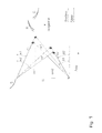
- das Diagramm eines Geschwindigkeitsdreiecks für eine im vorderen Teil des Kompressors angeordnete Stufe für den trockenen Betrieb und den Betrieb mit Wassereinspritzung;
- Fig. 2
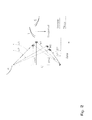
- das Diagramm eines Geschwindigkeitsdreiecks für eine im hinteren Teil des Kompressors angeordnete Stufe für den trockenen Betrieb und den Betrieb mit Wassereinspritzung
- Fig. 3
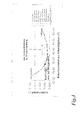
- die Änderung im Gitterverlust mit zunehmender Wassereinspritzung bei herkömmlicher Schaufelgeometrie und bei gemäss der Erfindung veränderter Schaufelgeometrie für eine im vorderen Teil des Kompressors angeordnete Stufe;
- Fig. 4
- die Änderung im Gitterverlust mit zunehmender Wassereinspritzung bei herkömmlicher Schaufelgeometrie und bei gemäss der Erfindung veränderter Schaufelgeometrie für eine im hinteren Teil des Kompressors angeordnete Stufe;
- Fig. 5
- die Konstanz des Gitterverlustes bei sich ändernder Wassereinspritzung für eine mittlere Stufe des Kompressors mit herkömmlicher Schaufelgeometrie;
- Fig. 6
- den schematisierten Aufbau eines mehrstufigen Axialkompressors, der Gegenstand der vorliegenden Erfindung ist.
- Fig. 1
- the diagram of a speed triangle for a arranged in the front part of the compressor stage for dry operation and operation with water injection;
- Fig. 2
- a diagram of a velocity triangle for a dry-type and water-injection stage located at the rear of the compressor
- Fig. 3
- the change in lattice loss with increasing water injection in conventional blade geometry and in accordance with the invention changed blade geometry for a arranged in the front part of the compressor stage;
- Fig. 4
- the change in lattice loss with increasing water injection in conventional blade geometry and in accordance with the invention changed blade geometry for a arranged in the rear of the compressor stage;
- Fig. 5
- the constancy of the lattice loss with changing water injection for a middle stage of the compressor with conventional blade geometry;
- Fig. 6
- the schematic structure of a multi-stage axial compressor, the subject of the present invention.
Die Erfindung geht aus von einem Axialkompressor 10, wie er schematisch in Fig.
6 wiedergegeben ist. Der Axialkompressor 10 hat einen Rotor 11, der konzentrisch
in einem Stator 13 um eine Rotorachse 12 drehbar angeordnet ist. Der
Axialkompressor 10 hat eine Mehrzahl von Kompressorstufen ST1,..,ST5, die
zwischen einem Kompressoreingang 14 und einem Kompressorausgang 15 in
axialer Richtung hintereinander angeordnet sind. Die Stufen ST1,..,ST5 umfassen
jeweils einen Kranz von Rotorschaufeln oder Laufschaufeln R und einen Kranz
von Statorschaufeln oder Leitschaufeln S. Durch den Axialkompressor strömt vom
Kompressoreingang 14 zum Kompressorausgang 15 ein Medium, insbesondere
Luft, das komprimiert wird. Ist der Kompressor Teil einer Gasturbine, dient die
komprimierte Luft als Verbrennungsluft im Brenner der Gasturbine.The invention is based on an axial compressor 10, as shown schematically in FIG.
6 is reproduced. The axial compressor 10 has a
Wie aus der Darstellung der Rotorschaufeln R und Statorschaufeln S in den Fig. 1 und 2 zu erkennen ist, prägen die rotierenden Rotorschaufeln R dem durch den Kompressor strömenden Medium eine Strömungsgeschwindigkeit auf. Die Statorschaufeln S bewirken eine nachfolgende Umlenkung, bevor das zu komprimierende Medium in die nächste Stufe eintritt. Die Rotorschaufeln R haben eine lineare Rotorgeschwindigkeit U. Die absoluten Strömungsgeschwindigkeiten des Mediums am Eingang und am Ausgang der Stufe sind c1 bzw. c2. Sie schliessen mit der axialen Richtung einen Winkel α1 bzw. α2 ein. Die relativen Strömungsgeschwindigkeiten des Mediums im Bezug auf die Rotorschaufeln R am Eingang und am Ausgang der Stufe sind w1 bzw. w2. Sie schliessen mit der axialen Richtung einen Winkel von β1 bzw. β2 ein. Die Komponenten der absoluten Strömungsgeschwindigkeiten c1 bzw. c2 in axialer Richtung sind mit cm1 und cm2 bezeichnet. Verglichen sind in den Fig. 1 und 2 jeweils der Fall ohne Wassereinspritzung ("Trocken"; durchgezogenen Linien) und mit Wassereinspritzung ("Nass"; punktierte Linien). Die verschiedenen Strömungsgeschwindigkeiten U, c und w bilden dabei ein charakteristisches Geschwindigkeitsdreieck. Der in Fig. 1 dargestellte Fall gilt für die im vorderen Bereich des Kompressors angeordneten Stufen; der in Fig. 2 dargestellte Fall für die im hinteren Bereich angeordneten Stufen.As is apparent from the illustration of the rotor blades R and stator blades S in FIGS and 2 can be seen, the rotating rotor blades R shape that through the Compressor flowing medium to a flow velocity. The Stator blades S cause a subsequent deflection before that too Compressing medium enters the next stage. The rotor blades R have a linear rotor speed U. The absolute flow velocities of the medium at the entrance and at the exit of the stage are c1 and c2 respectively. she enclose an angle α1 or α2 with the axial direction. The relative Flow velocities of the medium with respect to the rotor blades R at the entrance and exit of the stage are w1 and w2, respectively. They close with the axial direction an angle of β1 or β2. The components of absolute flow velocities c1 and c2 in the axial direction are with cm1 and cm2. Compared in Figs. 1 and 2, respectively, the case without Water injection ("dry", solid lines) and with Water injection ("wet", dotted lines). The different Flow velocities U, c and w form a characteristic Velocity triangle. The case shown in Fig. 1 applies to the front Area of the compressor arranged stages; the case shown in Fig. 2 for the steps arranged in the rear area.
Gemäss Fig. 1 führt die Verdampfung des eingespritzten Wassers in den vorderen Stufen zu einem Ansteigen der axialen Strömungsgeschwindigkeit cm1 bzw. cm2 (Übergang vom durchgezogenen Vektor zum punktiert gezeichneten Vektor). Damit verbunden ist eine Änderung (Verkleinerung) des Winkels β1. Auf der in Fig. 3 dargestellten zugehörigen Kurve der Gitterverluste in Abhängigkeit vom Eintrittswinkel des Schaufelgitters (die Kreise gelten für SD = Standard-Design; die Dreiecke gelten für EWD = Design mit Eintrittswinkeländerung) wandern die zugehörigen Punkte (Kreise) bei Verkleinerung des Winkels nach links zur "Sperrgrenzen"-Seite der Kurve und führen zu erhöhten Verlusten ("Delta Verlust") in der Stufe. Um die mit dieser Winkeländerung verbundenen Verluste zu vermeiden, werden die Rotorschaufeln R nun in ihrer Geometrie so verändert, dass sie bezüglich der relativen Strömungsgeschwindigkeit von vornherein einen zusätzlichen Winkelbetrag aufweisen. Damit liegt der Ausgangspunkt für den Betrieb ohne Wassereinspritzung nicht mehr im absoluten Minimum der Verlustkurve der Fig. 3. Die zu einem bestimmten Prozentsatz an Wassereinspritzung gehörenden Punkte auf der Verlustkurve verschieben sich nach rechts; die Kreise gehen in zugeordnete Dreiecke über, die jeweils einem um etwa 2° höheren Winkel entsprechen. Wird nun zunehmend Wasser in den Kompressor eingespritzt, erreichen die Dreiecke bei einer Wassereinspritzung von etwa 2% des angesaugten trockenen Luftmassenstroms den Minimalwert der Verlustkurve, sodass sich durch die Wassereinspritzung der Verlust nicht erhöht, sondern minimiert. Die voreingestellte Winkelerhöhung wird gemäss Fig. 1 dadurch erreicht, dass die Nasen der Rotorschaufeln R und nachfolgenden Statorschaufeln S im Sinne einer stärkeren Öffnung verändert werden (punktierte Linien der Schaufeln R und S in Fig. 1).According to FIG. 1, the evaporation of the injected water leads to the front Steps to increase the axial flow velocity cm1 or cm2 (Transition from solid vector to dotted vector). Associated with this is a change (reduction) in the angle β1. On the in Fig. 3 illustrated associated curve of the grid losses in dependence on Entry angle of the blade grid (the circles are for SD = standard design, the Triangles apply to EWD = design with entry angle change) associated points (circles) when reducing the angle to the left to "Blocking limits" side of the curve and lead to increased losses ("Delta loss") in the stage. To the losses associated with this change in angle avoid the rotor blades R are so changed in their geometry, that they have a relative to the flow velocity from the outset have additional angular amount. This is the starting point for the Operation without water injection is no longer in the absolute minimum of Loss curve of Fig. 3. The to a certain percentage of Water injection belonging points on the loss curve shift to the right; the circles go into associated triangles, each one um correspond to about 2 ° higher angle. Will now increasingly water in the Compressor injected, reach the triangles at a water injection of about 2% of the sucked dry air mass flow the minimum value of Loss curve, so that the water injection does not increase the loss, but minimized. The preset angle increase is shown in FIG. 1 achieved in that the lugs of the rotor blades R and subsequent Stator blades S are changed in the sense of a stronger opening (dotted Lines of the blades R and S in Fig. 1).
Bei den im hinteren Bereich angeordneten Stufen des Kompressors 10 sind die Verhältnisse genau anders herum ausgebildet (Fig. 2 und 4): Die erhöhte Dichte des strömenden Mediums, die eine Folge der Abkühlung durch das verdampfende Wasser ist, führt zu einer Abnahme der axialen Strömungsgeschwindigkeit cm1 bzw. cm2 im Vergleich zum Betriebe ohne Wassereinspritzung. Die zugehörigen Arbeitspunkte (Kreise) auf der Verlustkurve der Fig. 4 wandern dadurch nach rechts zur "Ablösungs"-Seite der Kurve und verursachen so höhere Verluste. Durch eine Voreinstellung in Form eines verminderten Winkels (Übergang von den Kreisen nach links zu den Dreiecken in Fig. 4) kann auch hier ein mit der Wassereinspritzung zunehmender Verlust verhindert werden. Die Nasen der Schaufeln R und S werden gemäss den punktierten Kurven in Fig. 2 hin zu einer stärker geschlossenen Geometrie verändert. Voreinstellung zur "Sperrgrenzen"-Seite hin).In the arranged at the rear of the stages of the compressor 10 are the Conditions designed exactly the other way around (Figures 2 and 4): The increased density of the flowing medium, which is a consequence of the cooling by the evaporating Water is, leads to a decrease in the axial flow velocity cm1 or cm2 compared to operations without water injection. The associated Operating points (circles) on the loss curve of Fig. 4 thereby migrate right to the "detachment" side of the curve causing higher losses. By default in the form of a reduced angle (transition from the Circles to the left to the triangles in Fig. 4) can also be here with the Water injection increasing loss can be prevented. The noses of the Blades R and S become, according to the dotted curves in FIG changed more closed geometry. Presetting to the "Blocking Limits" page HIN).
Wie man an den Fig. 3 und 4 leicht erkennt, wird durch die Geometrieveränderung der Schaufeln der flache Minimalbereich der Verlustkurven voll ausgenutzt. Der Winkel der relativen Strömungsgeschwindigkeit wird dazu so verschoben, dass sich der Arbeitspunkt für den gesamten Bereich der Wassereinspritzung bis hinauf zu 2% praktisch im breiten Minimalbereich der Kurve bewegt. Der positive Gesamteffekt der Voreinstellung kann dabei bis zu einem Prozent oder mehr im Kompressorwirkungsgrad ausmachen.As can easily be seen in FIGS. 3 and 4, the geometry change the vanes fully exploited the flat minimum range of loss curves. Of the Angle of relative flow velocity is shifted so that the working point for the whole range of water injection up to 2% practically in the wide minimum range of the curve moves. The positive Total effect of the presetting can be up to one percent or more in the Make compressor efficiency.
Die im vorderen Bereich des Axialkompressors 10 angeordneten Stufen, bei denen gemäss Fig. 1 und 3 eine Voreinstellung zur "Ablösungs"-Seite hin eingesetzt wird, und die im hinteren Bereich des Axialkompressors 10 angeordneten Stufen, bei denen gemäss Fig. 2 und 4 eine Voreinstellung zur "Sperrgrenzen"-Seite hin eingesetzt wird, sind üblicherweise durch eine mittlere neutrale Stufe voneinander getrennt, in der die Wassereinspritzung gemäss Fig. 5 praktisch keine Verschiebung auf der Verlustkurve und damit auch keine steigenden Verluste verursacht. In dieser Stufe kann auf eine Änderung der Schaufelgeometrie (Voreinstellung) ohne Nachteile verzichtet werden.The arranged in the front region of the axial compressor 10 stages at those according to FIGS. 1 and 3, a default setting for "detachment" side is used, and in the rear region of the axial compressor 10th arranged stages in which according to FIGS. 2 and 4, a default setting for "Sperrgrenzen" side is inserted, are usually by a middle neutral stage separated from each other, in the water injection according to FIG. 5th virtually no shift on the loss curve and therefore none causing rising losses. At this stage may be due to a change in the Blade geometry (default) without disadvantages.
- 1010
- AxialkompressorAxial Compressor
- 1111
- Rotorrotor
- 1212
- Rotorachserotor axis
- 1313
- Statorstator
- 1414
- Kompressoreingangcompressor input
- 1515
- Kompressorausgangcompressor output
- ST1,..,ST5ST1, .., ST5
- Stufestep
- RR
- Rotorschaufel rotor blade
- SS
- Statorschaufelstator
- α1,α2α1, α2
- Winkel der absoluten Strömungsgeschwindigkeit cAngle of absolute flow velocity c
- β1,β2β1, β2
- Winkel der relativen Strömungsgeschwindigkeit wAngle of relative flow velocity w
- c1,c2c1, c2
- absolute Strömungsgeschwindigkeitabsolute flow velocity
- cm1,cm2cm1, cm2
- axiale Strömungsgeschwindigkeitaxial flow velocity
- UU
- lineare Rotorgeschwindigkeitlinear rotor speed
- w1,w2w1, w2
- Strömungsgeschwindigkeit relativ zur RotorschaufelFlow velocity relative to the rotor blade
Claims (4)
Applications Claiming Priority (2)
| Application Number | Priority Date | Filing Date | Title |
|---|---|---|---|
| DE10342097 | 2003-09-10 | ||
| DE10342097A DE10342097A1 (en) | 2003-09-10 | 2003-09-10 | Axial Compressor |
Publications (1)
| Publication Number | Publication Date |
|---|---|
| EP1522696A2 true EP1522696A2 (en) | 2005-04-13 |
Family
ID=34258588
Family Applications (1)
| Application Number | Title | Priority Date | Filing Date |
|---|---|---|---|
| EP04104153A Withdrawn EP1522696A2 (en) | 2003-09-10 | 2004-08-31 | Gas turbine axial compressor with water injection |
Country Status (4)
| Country | Link |
|---|---|
| US (1) | US7165935B2 (en) |
| EP (1) | EP1522696A2 (en) |
| CA (1) | CA2480136A1 (en) |
| DE (1) | DE10342097A1 (en) |
Cited By (2)
| Publication number | Priority date | Publication date | Assignee | Title |
|---|---|---|---|---|
| DE102008003333A1 (en) | 2008-01-07 | 2009-07-09 | Dirk Landau | Internal-combustion engine for use as electric heater in e.g. hotel, has exhaust-gas turbine with compressor arranged in fresh-air line, where water in droplet form is supplied to exhaust gas of combustion chamber via nozzle |
| EP2551486A1 (en) * | 2011-07-25 | 2013-01-30 | Alstom Technology Ltd | Method for injecting water into a multistage axial compressor of a gas turbine |
Families Citing this family (5)
| Publication number | Priority date | Publication date | Assignee | Title |
|---|---|---|---|---|
| WO2007017498A1 (en) * | 2005-08-10 | 2007-02-15 | Alstom Technology Ltd | Method for the aerodynamic design of a compressor of a turbine engine |
| US8475117B2 (en) * | 2009-11-10 | 2013-07-02 | General Electric Company | Gas turbine compressor and method of operation |
| US8567177B1 (en) | 2012-11-30 | 2013-10-29 | Yoganeck, LLC | Gas turbine engine system with water recycling feature |
| CN111456965B (en) * | 2020-04-16 | 2022-02-15 | 李伟 | Centrifugal axial flow turbine and novel jet engine mode and operation method |
| CN114458632B (en) * | 2020-11-09 | 2023-08-04 | 中国航发上海商用航空发动机制造有限责任公司 | Mechanical limiting structure for adjustable stator blade of air compressor |
Family Cites Families (7)
| Publication number | Priority date | Publication date | Assignee | Title |
|---|---|---|---|---|
| DE844632C (en) * | 1948-10-02 | 1952-07-24 | Siemens Ag | Multi-stage axial compressor, the degree of reaction of which changes gradually |
| US4295784A (en) * | 1979-09-26 | 1981-10-20 | United Technologies Corporation | Variable stator |
| DE4407829A1 (en) * | 1994-03-09 | 1995-09-14 | Abb Patent Gmbh | Method for quasi-isothermal compression of air |
| JP2877098B2 (en) * | 1995-12-28 | 1999-03-31 | 株式会社日立製作所 | Gas turbines, combined cycle plants and compressors |
| US5867977A (en) * | 1996-05-14 | 1999-02-09 | The Dow Chemical Company | Method and apparatus for achieving power augmentation in gas turbines via wet compression |
| US6398518B1 (en) * | 2000-03-29 | 2002-06-04 | Watson Cogeneration Company | Method and apparatus for increasing the efficiency of a multi-stage compressor |
| GB2382848A (en) * | 2001-12-06 | 2003-06-11 | Alstom | Gas turbine wet compression |
-
2003
- 2003-09-10 DE DE10342097A patent/DE10342097A1/en not_active Ceased
-
2004
- 2004-08-31 EP EP04104153A patent/EP1522696A2/en not_active Withdrawn
- 2004-09-01 US US10/931,065 patent/US7165935B2/en not_active Expired - Fee Related
- 2004-09-03 CA CA002480136A patent/CA2480136A1/en not_active Abandoned
Cited By (4)
| Publication number | Priority date | Publication date | Assignee | Title |
|---|---|---|---|---|
| DE102008003333A1 (en) | 2008-01-07 | 2009-07-09 | Dirk Landau | Internal-combustion engine for use as electric heater in e.g. hotel, has exhaust-gas turbine with compressor arranged in fresh-air line, where water in droplet form is supplied to exhaust gas of combustion chamber via nozzle |
| EP2551486A1 (en) * | 2011-07-25 | 2013-01-30 | Alstom Technology Ltd | Method for injecting water into a multistage axial compressor of a gas turbine |
| CH705323A1 (en) * | 2011-07-25 | 2013-01-31 | Alstom Technology Ltd | A method for injecting water in a multistage axial compressor of a gas turbine. |
| US10480404B2 (en) | 2011-07-25 | 2019-11-19 | Ansaldo Energia Switzerland AG | Method for injecting water into a multistage axial compressor of a gas turbine |
Also Published As
| Publication number | Publication date |
|---|---|
| CA2480136A1 (en) | 2005-03-10 |
| DE10342097A1 (en) | 2005-04-07 |
| US20050063819A1 (en) | 2005-03-24 |
| US7165935B2 (en) | 2007-01-23 |
Similar Documents
| Publication | Publication Date | Title |
|---|---|---|
| DE60133629T2 (en) | METHOD FOR OPERATING A GAS TURBINE WITH ADJUSTABLE RODS | |
| DE69915283T2 (en) | CIRCULAR WHEEL FOR TURBOMA MACHINES | |
| DE69831109T2 (en) | Cooling air supply system for the blades of a gas turbine | |
| DE60018817T2 (en) | Chilled gas turbine blade | |
| EP1113145B1 (en) | Blade for gas turbines with metering section at the trailing edge | |
| EP2179143B1 (en) | Gap cooling between combustion chamber wall and turbine wall of a gas turbine installation | |
| DE2262883A1 (en) | CENTRIFUGAL PUMP WITH VARIABLE DIFFUSER | |
| DE1817430A1 (en) | Regenerative compressor | |
| EP2835522B2 (en) | Device and method for letting off compressor air in an engine | |
| DE2031612A1 (en) | Multi-stage axial compressor with an air discharge system as an intermediate stage | |
| DE102007017826B4 (en) | turbocharger | |
| WO2006048401A1 (en) | Optimised turbine stage for a turbine engine and layout method | |
| DE2454054A1 (en) | INTERNAL POWER PLANT AND GAS GENERATOR FOR GAS TURBINE ENGINES | |
| DE102008044505B4 (en) | centrifugal compressors | |
| DE102015122928A1 (en) | Gas turbine seal | |
| EP3009683A1 (en) | Device and method for bleeding compressor air in an engine | |
| EP3290644A1 (en) | Gas turbine | |
| EP1522696A2 (en) | Gas turbine axial compressor with water injection | |
| WO2007033649A1 (en) | Cooling system for a compressor casing | |
| WO2005090755A1 (en) | Gas turbine with a compressor housing which is protected against cooling down and method for operating a gas turbine | |
| DE3132134A1 (en) | METHOD AND DEVICE FOR REDUCING THE FLOW SECTION OF THE EXHAUST GAS IN THE CONTROL WALL OF A TURBO COMPRESSOR FOR AN INTERNAL COMBUSTION ENGINE | |
| DE102008051980A1 (en) | Air supply device for fuel cell for passenger car, has compressor including radial diffuser whose effective flow cross section is changeable by air guiding element of compressor | |
| DE102014115963A1 (en) | Rotor-cooling | |
| EP2805059A1 (en) | Method and device for stabilizing a compressor current | |
| EP1632650B1 (en) | Steam turbine |
Legal Events
| Date | Code | Title | Description |
|---|---|---|---|
| PUAI | Public reference made under article 153(3) epc to a published international application that has entered the european phase |
Free format text: ORIGINAL CODE: 0009012 |
|
| AK | Designated contracting states |
Kind code of ref document: A2 Designated state(s): AT BE BG CH CY CZ DE DK EE ES FI FR GB GR HU IE IT LI LU MC NL PL PT RO SE SI SK TR |
|
| AX | Request for extension of the european patent |
Extension state: AL HR LT LV MK |
|
| STAA | Information on the status of an ep patent application or granted ep patent |
Free format text: STATUS: THE APPLICATION IS DEEMED TO BE WITHDRAWN |
|
| 18D | Application deemed to be withdrawn |
Effective date: 20130301 |