EP1522683B1 - Commande de soupape - Google Patents
Commande de soupape Download PDFInfo
- Publication number
- EP1522683B1 EP1522683B1 EP20030103691 EP03103691A EP1522683B1 EP 1522683 B1 EP1522683 B1 EP 1522683B1 EP 20030103691 EP20030103691 EP 20030103691 EP 03103691 A EP03103691 A EP 03103691A EP 1522683 B1 EP1522683 B1 EP 1522683B1
- Authority
- EP
- European Patent Office
- Prior art keywords
- tappet
- face
- central axis
- control element
- valve
- Prior art date
- Legal status (The legal status is an assumption and is not a legal conclusion. Google has not performed a legal analysis and makes no representation as to the accuracy of the status listed.)
- Expired - Lifetime
Links
- 230000000295 complement effect Effects 0.000 claims description 4
- 238000000034 method Methods 0.000 claims description 4
- 230000002093 peripheral effect Effects 0.000 claims description 2
- 238000002485 combustion reaction Methods 0.000 description 5
- 230000002349 favourable effect Effects 0.000 description 2
- 238000005096 rolling process Methods 0.000 description 2
- 238000006073 displacement reaction Methods 0.000 description 1
- 238000005553 drilling Methods 0.000 description 1
- 230000007704 transition Effects 0.000 description 1
Images

Classifications
-
- F—MECHANICAL ENGINEERING; LIGHTING; HEATING; WEAPONS; BLASTING
- F01—MACHINES OR ENGINES IN GENERAL; ENGINE PLANTS IN GENERAL; STEAM ENGINES
- F01L—CYCLICALLY OPERATING VALVES FOR MACHINES OR ENGINES
- F01L1/00—Valve-gear or valve arrangements, e.g. lift-valve gear
- F01L1/12—Transmitting gear between valve drive and valve
- F01L1/14—Tappets; Push rods
- F01L1/143—Tappets; Push rods for use with overhead camshafts
-
- F—MECHANICAL ENGINEERING; LIGHTING; HEATING; WEAPONS; BLASTING
- F01—MACHINES OR ENGINES IN GENERAL; ENGINE PLANTS IN GENERAL; STEAM ENGINES
- F01L—CYCLICALLY OPERATING VALVES FOR MACHINES OR ENGINES
- F01L13/00—Modifications of valve-gear to facilitate reversing, braking, starting, changing compression ratio, or other specific operations
- F01L13/0015—Modifications of valve-gear to facilitate reversing, braking, starting, changing compression ratio, or other specific operations for optimising engine performances by modifying valve lift according to various working parameters, e.g. rotational speed, load, torque
Definitions
- the invention relates to a n valve train with a valve, which is associated with a plunger with a profiled face, wherein at least one control acts on the profiled end face in such a way that the plunger is movable along a central axis.
- the invention also relates to a method for operating a valve train with a valve, which is assigned a plunger with profiled end face, wherein at least one control element acts on the profiled surface, so that the plunger is moved along a central axis.
- valve trains are known.
- the individual valves should open at low engine speeds with a short opening time, little overlap and low lift.
- the individual valves should open with a long opening time, high overlap and a large stroke. This is arranged by means of a camshaft on the cam, which interacts with a plunger.
- a cam mechanism with a cam is disclosed.
- the cam is basically round in shape and has a projection.
- the projection extends radially outward along a portion of its circumference.
- the cam mechanism also includes a cam follower disposed for reciprocal movement along an axis perpendicular to the axis of rotation of the cam.
- the cam acts on an end face of the cam follower. By abutment of the projection, a movement of the cam follower is caused.
- the end face of the cam follower is profiled.
- Means are provided for axially rotating the cam follower to change the angular orientation of the contoured end surface with respect to the axis of rotation of the cam to adjust the angular positions at which the projection engages and separates from the end surface. This sets the duration of the movement of the cam follower.
- the end face of the cam follower has a pair of flat surfaces inclined outwardly against the cam.
- the flat surfaces are smooth with each other connected, wherein a transition is designed arcuate.
- the cam follower is rotatable by an angular amount, by means of a rack mounted transversely to the cam follower and engaging teeth formed thereon.
- the invention has for its object to provide an improved valve train available to achieve a wide variation in the valve lift and or the valve timing with a structurally simple design.
- the invention is based on the finding that a rotational movement is converted into a translatory movement. This is conventionally achieved by two elements, the camshaft and the cam follower. In contrast, the invention combines both movements in one element, the ram. The plunger performs a rotational movement about its translational movement axis. This can be dispensed with a camshaft.
- the plunger advantageously has a circumferential toothed ring, in which a rotary drive engages.
- the rotary drive can be configured as an example worm drive or spur gear.
- the end face has a wave profile.
- the end face is in this case provided alternately with elevations and depressions, which are connected by means of flanks.
- the end face is also configured with their surveys that arises in the zenith of the survey a kind of inclined surface with an inclination in the direction of the central axis.
- the control is on the one hand on the profiled end face and on the other hand on an abutment. During the rotational movement of the plunger, the control passes alternately into a recess and on a subsequent survey, so that a lift curve for the valve is formed.
- control is stationary, so that a simple stroke curve is traversed.
- the control can be z. B. from at least a rolling element, at least one slider, a plain bearing or rolling element bearings exist.
- a preferred embodiment of the invention provides that the control is rotatably mounted in the circumferential direction of the plunger.
- a rotational movement of the control clockwise or counterclockwise relative to the central axis of the plunger by a certain angle so adjusts the lift curve of the respective valve relative to the angular position of a crankshaft of the internal combustion engine and the same specific angle.
- the control is movable in the direction of the central axis and away from this. Due to the different height of the survey and depth of the recess of the stroke of the plunger and thus the valve is adjustable.
- the control is at a maximum distance from the central axis. In this position, the face rotates with highest elevations and deepest depressions under the control.
- the valve can be reciprocated with a maximum lift along its central axis. At lower speeds, the control moves in the direction of the central axis. The stroke of the plunger and thus of the valve is thereby reduced.
- control of the control element in the respective position is achieved by means of a suitable control mechanism.
- This can z. B. hydraulically, pneumatically or servo-electrically operated.
- the control can be configured as a bearing, for example as a support bearing.
- a roller is arranged in a roller bearing.
- the control is in communication with the profiled end face, wherein the roller bearing rests against the counter bearing.
- the roller bearing rests against the thrust bearing.
- the Control is non-positively connected on the one hand with the end face and the other with the counter-bearing. This is achieved by means of a valve spring.
- the bearing is designed as a sliding bearing.
- the control can also be designed as a disk.
- the disc preferably has a profiling complementary to the wave profile.
- the disc can be arranged rotationally fixed and adjusted by certain phase angle. It is also possible that the disc rotates in opposite directions to the direction of rotation of the plunger.
- the use of a disk is advantageously a line contact with the end face.
- an improved valve train which achieves a large variation width of the valve lift, the opening time and the control times with a structurally simple design.
- valve trains can also be provided with a plurality of rams and / or disks. Although it is possible to dispense with a camshaft, it is possible to provide a combination of a camshaft with a ram that rotates about its central axis.
- the invention relates to methods which are suitable for carrying out the valve drives described above.
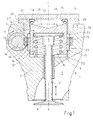
- FIG. 1 shows a valve train 1 with a valve 2.
- the valve 2 is received in a bore 3 of a cylinder head 4 of an internal combustion engine.
- the valve 2 protrudes with a spring plate 5 into the bore 3.
- the valve 2 With its valve disk 6, the valve 2 is disposed within a combustion chamber.
- the valve disk 6 is adapted to an inlet or outlet channel 7.
- the valve 2 is associated with a valve spring 8 in a conventional manner.
- the valve 2 is associated with a plunger 9.
- the plunger 9 is designed as a one-sided open rotationally symmetrical hollow body with a front plate 11 and a cylindrical wall 12.
- the cylindrical wall 12 is also referred to as a tappet shirt.
- the end plate 11 has a profiled end face 13. With a profiled end face 13 opposite planar support surface of the plunger 9 is preferably rotatably on the spring plate 5 or at the valve stem end.
- a peripheral ring gear 14 is arranged on the outside thereof.
- a rotary drive 16 which is arranged in the cylinder head 4.
- the rotary drive 16 is exemplified as a worm drive with a shaft 18 and a toothed ring 19, wherein the toothed ring 19 driven by the shaft 18 engages in the ring gear 14.
- the plunger 9 despite the engagement of the toothed ring 19 in the ring gear 14 can perform a stroke along its central axis Y-Y, the toothed ring 19 preferably has on its inner side facing the ring gear 14 a straight toothing, which is configured complementary to the teeth of the ring gear 14.
- the plunger 9 is rotated by means of a rotationally driven roller with corresponding teeth.
- an embodiment with a plurality of support rollers is conceivable that would be circumferentially distributed around the plunger 9.
- the rotationally driven roller and the support roller would be stored in a conventional manner.
- the plunger 9 can rotate about its central axis Y-Y.
- the center axis Y-Y is preferably congruent to a center axis of the valve 2.
- the bore 3 is formed stepwise with several sections. With a base portion 21, the bore 3 is adapted to the outer diameter of the plunger 9, wherein a gap 22 between the outside of the plunger 9 and the bore wall is formed. At the base portion 21, a sprocket portion 23 connects. The sprocket portion 23 has a larger diameter than the base portion 22. The sprocket portion 23 is adapted to the outer diameter of the sprocket 14. The sprocket section 23 merges into a toothed ring section 24. The toothed ring section 24 has a larger diameter than the toothed rim section 23, and is connected to the toothed ring 19 customized. The diameter of the toothed ring portion 24 represents the largest bore diameter.
- a fastener 26 is arranged in the bore 3.
- the fastening element 26 is designed as a sleeve 27 with a support flange 28. With its bearing flange 28, the fastening element 26 is fastened with a fastening side 29 on the cylinder head 4.
- the sleeve 27 protrudes into the bore 3 and is substantially free of play on the bore wall.
- the sleeve 27 has an inner diameter which corresponds to that of the base portion 21 of the bore 3.
- a support flange 28 opposite end portion 31 of the sleeve 27 has a step 32, so that a Hubaus originallyung 33 is formed for the ring gear 14.
- the lifting recess 33 has a diameter corresponding to the toothed rim section 23. Advantages of this embodiment will be explained below.
- the end portion 31 is adapted to the rotary drive 16, preferably rounded.
- an abutment 34 is attached at the opposite side to the mounting side 29 of the support flange 28, an abutment 34 is attached.
- the counter-bearing 34 is configured in the illustrated embodiment as a cover plate and closes the bore 3.
- a kraftformschlüssige screw can be selected.
- a continuous screw can be selected so that the anvil 34 and the fastener 26 are fastened to the cylinder head 4 at the same time.
- control element 36 On the end face 13, at least one control element 36 is arranged. In the illustrated embodiment, two controls 36 are arranged on the end face 13. Since both controls 36 are designed equal only one will be described.
- the control element 36 is designed as a support bearing with a roller 37 and a roller bearing 38.
- the roller 37 is rotatably received by the roller bearing 38. With its roller 37, the control element 36 rests on the profiled end face 13. With its roller bearing 39, the control element 36 bears against the abutment 34.
- the control element 36 is associated with a control mechanism, not shown, and on the one hand in the direction of the central axis Y-Y and the other directed away from this continuously variable. This is illustrated by means of the double arrow 41. In the circumferential direction of the plunger 9, the controls 36 are preferably rotationally fixed. The benefits are described below.
- FIG. 2 an exemplary profiling of the end face 13 is shown.
- the end face 13 has a wave profile with elevations 42 and recesses 43.
- the elevations 42 go over rounded flanks 44 in the recesses 43 and vice versa.
- the flanks 44 each have a concave and a convex portion, which merge smoothly into each other.
- each two diametrically opposite elevations 42 and recesses 43 are shown.
- more surveys 42 and recesses 43 may be provided.
- more controls 36 could be provided.
- an even number of elevations 42 and depressions 43 are preferably selected.
- FIG. 2 shows, profiling of the end surface 13 changes with increasing distance from the central axis YY.
- the elevations 42 are seen in cross-section smaller, so that in the zenith 46 a kind of inclined plane is formed, which tends in the direction of the central axis YY ( FIG. 1 ).
- the recesses 43 are directed away from the central axis YY accordingly larger.
- This is a largest survey 42 a largest recess 43 and a smallest survey 42 assigned a smallest recess 43.
- a middle elevation 42 is associated with a central depression 43. This is in the FIG. 2 represented by exemplary lifting curves 47,48,49.
- FIG. 1 the controls 36 are applied to a largest survey 42. In this position, the distance to the central axis YY is maximum. Now rotates the plunger 9 about its central axis YY causes the rotational movement opening and closing of the valve 2, by the roller 37 alternately the elevations 42 and recesses 43rd passes. In this case, the profiled end face 13 rotates below the control member 36, which is fixed in the circumferential direction of the tappet 9 in a rotationally fixed manner FIG. 2 represented by the lift curve 47, which represents a maximum lift curve. In order for a rotational movement of the plunger 9 is converted into a translational movement of the plunger 9. The translational movement is transmitted to the valve 2. At the maximum lift curve, the valve 2 has the maximum lift.
- the control element 36 is always positively connected to the end face 13 and the anvil 34.
- the Hubausappelung 33 is adapted by its design to the maximum stroke, so that an undisturbed lifting movement of the plunger 9 despite the ring gear 14 is possible.
- the control mechanism causes a stepless displacement of the controls 36 from the in FIG. 1 shown position toward the central axis YY.
- the lift curve 48 is shown here as the average lift curve and the lift curve 49 as the low lift curve.
- the controls 36 are synchronously displaced in any position, so that there is a large number of lifting curves, which are not shown for reasons of clarity.
Landscapes
- Engineering & Computer Science (AREA)
- Mechanical Engineering (AREA)
- General Engineering & Computer Science (AREA)
- Valve-Gear Or Valve Arrangements (AREA)
- Valve Device For Special Equipments (AREA)
Claims (14)
- Commande de soupape comprenant une soupape (2), à laquelle est associé un poussoir (9) ayant une surface frontale profilée (13), au moins un élément de commande (36) agissant sur la surface frontale profilée (13) de telle sorte que le poussoir (9) puisse se déplacer le long de son axe médian (Y-Y),
caractérisée en ce que
le poussoir (9) peut tourner au moyen d'un entraînement en rotation (16) sur toute sa périphérie autour de son axe médian (Y-Y), le poussoir (9) se déplaçant simultanément en translation le long de son axe médian (Y-Y) et la surface frontale (13) présentant un profil ondulé avec des rehaussements (42) et des renfoncements (43) en alternance, qui se prolongent les uns dans les autres par le biais de flancs arrondis (44). - Commande de soupape selon la revendication 1,
caractérisée en ce que
le poussoir (9) présente une couronne dentée (14) dans laquelle s'engage l'entraînement en rotation (16). - Commande de soupape selon la revendication 1 ou 2,
caractérisée en ce que
l'élément de commande (36) est fixe et/ou est connecté d'une seule pièce à la culasse (4) ou à une partie connectée à la culasse (4). - Commande de soupape selon au moins l'une quelconque des revendications précédentes,
caractérisée en ce que
l'élément de commande (36) est monté de manière mobile en rotation et/ou peut être déplacé de manière mobile en rotation par rapport à l'axe médian du poussoir dans le sens des aiguilles d'une montre ou dans le sens inverse. - Commande de soupape selon l'une quelconque des revendications précédentes,
caractérisée en ce que
le profilage de la surface frontale (13) varie avec l'augmentation de la distance à l'axe médian (Y-Y), les rehaussements (42) devenant de plus en plus petits en section transversale dans la direction de l'axe médian (Y-Y) de sorte qu'un type de plan incliné soit formé dans leur zénith (46), lequel s'incline dans la direction de l'axe médian (Y-Y), les renfoncements (43) devenant de plus en plus grands en s'écartant de l'axe médian (Y-Y). - Commande de soupape selon l'une quelconque des revendications précédentes,
caractérisée en ce que
l'élément de commande (36) s'applique d'une part contre la surface frontale profilée (13) et d'autre part contre un palier conjugué (34). - Commande de soupape selon l'une quelconque des revendications précédentes,
caractérisée en ce que
l'élément de commande (36) peut être déplacé en continu dans la direction vers et depuis l'axe médian (Y-Y), et est rigide dans la direction périphérique du poussoir (9). - Commande de soupape selon l'une quelconque des revendications précédentes,
caractérisée en ce que
l'élément de commande (36) est configuré sous forme de palier. - Commande de soupape selon au moins l'une quelconque des revendications 1 à 8,
caractérisée en ce que
l'élément de commande (36) est configuré sous forme de disque qui présente un profilage complémentaire de la surface frontale profilée (13). - Commande de soupape selon au moins l'une quelconque des revendications 1 à 9,
caractérisée en ce que
au moins un poussoir (9) est en prise avec une courroie dentée (14) d'au moins un deuxième poussoir (9) par le biais d'une courroie dentée (14) . - Commande de soupape selon l'une quelconque des revendications 1 à 10,
caractérisée en ce que
le poussoir (9) présente plus d'une surface profilée (13). - Commande de soupape selon la revendication 11,
caractérisée en ce que
le poussoir (9) est guidé de force au moyen d'un deuxième élément de commande (36) dans le sens de l'axe de rotation. - Procédé pour la commande d'une soupape selon l'une quelconque des revendications précédentes, comprenant une soupape (2) à laquelle est associé un poussoir (9) avec une surface frontale profilée (13), au moins un élément de commande (36) agissant sur la surface frontale profilée (13) de sorte que le poussoir (9) soit déplacé le long de son axe médian (Y-Y),
caractérisé en ce que
le poussoir (9) est tourné au moyen d'un entraînement en rotation (16) sur toute sa périphérie autour de son axe médian (Y-Y), le poussoir (9) se déplaçant simultanément en translation le long de son axe médian (Y-Y), et la surface frontale (13) présentant un profil ondulé avec des rehaussements (42) et des renfoncements (43) en alternance, qui se prolongent les uns dans les autres par le biais de flancs arrondis (44). - Procédé selon la revendication 13,
caractérisé en ce que
la surface frontale (13) tourne sous l'élément de commande (36), l'élément de commande (36) étant en contact en alternance avec des rehaussements (42) et des renfoncements (43) de la surface frontale (13), et l'élément de commande (36) s'appliquant par engagement par force d'une part contre la surface frontale (13) et d'autre part contre un palier conjugué (34), de sorte qu'un mouvement de levage du poussoir (9) le long de son axe médian (Y-Y), qui se transmet à la soupape (2), soit produit au moyen de l'alternance des rehaussements (42) et des renfoncements (43).
Priority Applications (2)
| Application Number | Priority Date | Filing Date | Title |
|---|---|---|---|
| DE50309328T DE50309328D1 (de) | 2003-10-06 | 2003-10-06 | Ventiltrieb |
| EP20030103691 EP1522683B1 (fr) | 2003-10-06 | 2003-10-06 | Commande de soupape |
Applications Claiming Priority (1)
| Application Number | Priority Date | Filing Date | Title |
|---|---|---|---|
| EP20030103691 EP1522683B1 (fr) | 2003-10-06 | 2003-10-06 | Commande de soupape |
Publications (2)
| Publication Number | Publication Date |
|---|---|
| EP1522683A1 EP1522683A1 (fr) | 2005-04-13 |
| EP1522683B1 true EP1522683B1 (fr) | 2008-03-05 |
Family
ID=34306979
Family Applications (1)
| Application Number | Title | Priority Date | Filing Date |
|---|---|---|---|
| EP20030103691 Expired - Lifetime EP1522683B1 (fr) | 2003-10-06 | 2003-10-06 | Commande de soupape |
Country Status (2)
| Country | Link |
|---|---|
| EP (1) | EP1522683B1 (fr) |
| DE (1) | DE50309328D1 (fr) |
Families Citing this family (1)
| Publication number | Priority date | Publication date | Assignee | Title |
|---|---|---|---|---|
| DE102009006894B4 (de) * | 2009-01-28 | 2010-10-14 | Iav Gmbh Ingenieurgesellschaft Auto Und Verkehr | Vorrichtung zur Schaltbetätigung eines hydraulischen Ventilspielausgleichselements |
Family Cites Families (5)
| Publication number | Priority date | Publication date | Assignee | Title |
|---|---|---|---|---|
| US4061115A (en) * | 1976-06-01 | 1977-12-06 | Predhome Jr Wilfred F | Valve train for internal combustion engine |
| GB8711993D0 (en) * | 1987-05-21 | 1987-06-24 | Jaguar Cars | Cam mechanisms |
| JPH0367010A (ja) * | 1989-08-04 | 1991-03-22 | Nippondenso Co Ltd | 内燃機関の吸排気弁駆動機構 |
| GB2327711B (en) * | 1997-07-30 | 2001-03-07 | Avl List Gmbh | Device for actuating of at least one valve of an internal combustion engine |
| JP2001329810A (ja) * | 2000-05-22 | 2001-11-30 | Toyota Motor Corp | バルブ駆動装置 |
-
2003
- 2003-10-06 EP EP20030103691 patent/EP1522683B1/fr not_active Expired - Lifetime
- 2003-10-06 DE DE50309328T patent/DE50309328D1/de not_active Expired - Lifetime
Also Published As
| Publication number | Publication date |
|---|---|
| EP1522683A1 (fr) | 2005-04-13 |
| DE50309328D1 (de) | 2008-04-17 |
Similar Documents
| Publication | Publication Date | Title |
|---|---|---|
| EP2291578B1 (fr) | Distribution pour les soupapes d'echange de gaz d'un moteur a combustion interne avec des supports de came doublement soutenus | |
| EP2315920B1 (fr) | Liaison par cannelures et mécanisme de distribution avec liaison par cannelures entre un arbre à cames et des supports de came déplaçables | |
| EP0798451B1 (fr) | Commande de soupape d'un moteur à combustion interne | |
| DE102009048621B4 (de) | Ventiltrieb für Gaswechselventile mit Verspannung von Grundnockenwelle und Nockenträger in Umfangs- oder Drehrichtung | |
| EP2739830B1 (fr) | Commande de soupape d'un moteur à combustion interne, moteur à combustion interne et procédé de fabrication d'une commande de soupape correspondante | |
| EP2702253B1 (fr) | Mécanisme de soupape destiné à des soupapes d'échange des gaz d'un moteur à combustion interne, comportant un arbre à cames de base et des supports de cames pouvant être déplacés entre deux ou plusieurs positions de déplacement discrètes situées entre des coussinets de l'arbre à cames de base | |
| EP2841723B1 (fr) | Mécanisme de distribution d'un moteur à combustion interne | |
| DE102009005731B4 (de) | Ventiltrieb für Gaswechselventile mit geneigter Doppel-Kugelraste | |
| WO2016023687A1 (fr) | Arbre à cames avec bloc de cames coulissantes | |
| WO2015176874A1 (fr) | Arbre à cames | |
| DE102009053250B4 (de) | Beschlag für einen Fahrzeugsitz und Fahrzeugsitz | |
| EP1522683B1 (fr) | Commande de soupape | |
| EP0518898B1 (fr) | Dispositif d'entrainement d'arbre a came | |
| EP3221567B1 (fr) | Commande de soupape pour moteur à combustion interne ainsi que le moteur à combustion interne correspondant | |
| DE102014214125B4 (de) | Stelleinrichtung zur Verstellung von Steuerzeiten einer Brennkraftmaschine | |
| EP0607509B1 (fr) | Dispositif de variation angulaire d'un arbre par rapport à son pignon d'entraînement, en particulier d'un arbre à cames par rapport à son pignon d'entraînement | |
| WO2015036401A1 (fr) | Déphaseur d'arbre à cames | |
| DE102018214698B4 (de) | Ventiltrieb für eine Brennkraftmaschine | |
| EP1636466A2 (fr) | Moteur a combustion interne | |
| DE10211969A1 (de) | Ventiltrieb für eine Hubkolben-Brennkraftmaschine | |
| EP1624161A1 (fr) | Dispositif permettant de transformer un mouvement rotatif en un mouvement de va et vient | |
| DE3706187A1 (de) | Antriebsvorrichtung fuer ein vorzugsweise linear verstellbar gefuehrtes maschinenteil | |
| DE10315493A1 (de) | Ventildrehvorrichtung | |
| DE4215057A1 (de) | Nockenwelle | |
| DE102021004124A1 (de) | Stellgetriebe und Wellgenerator für ein Stellgetriebe |
Legal Events
| Date | Code | Title | Description |
|---|---|---|---|
| PUAI | Public reference made under article 153(3) epc to a published international application that has entered the european phase |
Free format text: ORIGINAL CODE: 0009012 |
|
| AK | Designated contracting states |
Kind code of ref document: A1 Designated state(s): AT BE BG CH CY CZ DE DK EE ES FI FR GB GR HU IE IT LI LU MC NL PT RO SE SI SK TR |
|
| AX | Request for extension of the european patent |
Extension state: AL LT LV MK |
|
| 17P | Request for examination filed |
Effective date: 20051013 |
|
| AKX | Designation fees paid |
Designated state(s): DE FR GB |
|
| GRAP | Despatch of communication of intention to grant a patent |
Free format text: ORIGINAL CODE: EPIDOSNIGR1 |
|
| GRAS | Grant fee paid |
Free format text: ORIGINAL CODE: EPIDOSNIGR3 |
|
| GRAA | (expected) grant |
Free format text: ORIGINAL CODE: 0009210 |
|
| AK | Designated contracting states |
Kind code of ref document: B1 Designated state(s): DE FR GB |
|
| REG | Reference to a national code |
Ref country code: GB Ref legal event code: FG4D Free format text: NOT ENGLISH |
|
| REF | Corresponds to: |
Ref document number: 50309328 Country of ref document: DE Date of ref document: 20080417 Kind code of ref document: P |
|
| ET | Fr: translation filed | ||
| PLBE | No opposition filed within time limit |
Free format text: ORIGINAL CODE: 0009261 |
|
| STAA | Information on the status of an ep patent application or granted ep patent |
Free format text: STATUS: NO OPPOSITION FILED WITHIN TIME LIMIT |
|
| 26N | No opposition filed |
Effective date: 20081208 |
|
| PGFP | Annual fee paid to national office [announced via postgrant information from national office to epo] |
Ref country code: GB Payment date: 20140925 Year of fee payment: 12 |
|
| PGFP | Annual fee paid to national office [announced via postgrant information from national office to epo] |
Ref country code: DE Payment date: 20141028 Year of fee payment: 12 Ref country code: FR Payment date: 20140924 Year of fee payment: 12 |
|
| REG | Reference to a national code |
Ref country code: DE Ref legal event code: R119 Ref document number: 50309328 Country of ref document: DE |
|
| GBPC | Gb: european patent ceased through non-payment of renewal fee |
Effective date: 20151006 |
|
| PG25 | Lapsed in a contracting state [announced via postgrant information from national office to epo] |
Ref country code: DE Free format text: LAPSE BECAUSE OF NON-PAYMENT OF DUE FEES Effective date: 20160503 Ref country code: GB Free format text: LAPSE BECAUSE OF NON-PAYMENT OF DUE FEES Effective date: 20151006 |
|
| REG | Reference to a national code |
Ref country code: FR Ref legal event code: ST Effective date: 20160630 |
|
| PG25 | Lapsed in a contracting state [announced via postgrant information from national office to epo] |
Ref country code: FR Free format text: LAPSE BECAUSE OF NON-PAYMENT OF DUE FEES Effective date: 20151102 |