EP1522489A2 - Zuzammenklappbares Fahrzeug - Google Patents
Zuzammenklappbares Fahrzeug Download PDFInfo
- Publication number
- EP1522489A2 EP1522489A2 EP04256226A EP04256226A EP1522489A2 EP 1522489 A2 EP1522489 A2 EP 1522489A2 EP 04256226 A EP04256226 A EP 04256226A EP 04256226 A EP04256226 A EP 04256226A EP 1522489 A2 EP1522489 A2 EP 1522489A2
- Authority
- EP
- European Patent Office
- Prior art keywords
- vehicle
- rear frame
- frame assembly
- assemblies
- assembly
- Prior art date
- Legal status (The legal status is an assumption and is not a legal conclusion. Google has not performed a legal analysis and makes no representation as to the accuracy of the status listed.)
- Withdrawn
Links
Images


Classifications
-
- B—PERFORMING OPERATIONS; TRANSPORTING
- B62—LAND VEHICLES FOR TRAVELLING OTHERWISE THAN ON RAILS
- B62K—CYCLES; CYCLE FRAMES; CYCLE STEERING DEVICES; RIDER-OPERATED TERMINAL CONTROLS SPECIALLY ADAPTED FOR CYCLES; CYCLE AXLE SUSPENSIONS; CYCLE SIDE-CARS, FORECARS, OR THE LIKE
- B62K15/00—Collapsible or foldable cycles
- B62K15/006—Collapsible or foldable cycles the frame being foldable
-
- B—PERFORMING OPERATIONS; TRANSPORTING
- B62—LAND VEHICLES FOR TRAVELLING OTHERWISE THAN ON RAILS
- B62K—CYCLES; CYCLE FRAMES; CYCLE STEERING DEVICES; RIDER-OPERATED TERMINAL CONTROLS SPECIALLY ADAPTED FOR CYCLES; CYCLE AXLE SUSPENSIONS; CYCLE SIDE-CARS, FORECARS, OR THE LIKE
- B62K15/00—Collapsible or foldable cycles
-
- B—PERFORMING OPERATIONS; TRANSPORTING
- B62—LAND VEHICLES FOR TRAVELLING OTHERWISE THAN ON RAILS
- B62K—CYCLES; CYCLE FRAMES; CYCLE STEERING DEVICES; RIDER-OPERATED TERMINAL CONTROLS SPECIALLY ADAPTED FOR CYCLES; CYCLE AXLE SUSPENSIONS; CYCLE SIDE-CARS, FORECARS, OR THE LIKE
- B62K5/00—Cycles with handlebars, equipped with three or more main road wheels
- B62K5/02—Tricycles
- B62K5/023—Tricycles specially adapted for disabled riders, e.g. personal mobility type vehicles with three wheels
- B62K5/025—Tricycles specially adapted for disabled riders, e.g. personal mobility type vehicles with three wheels power-driven
-
- B—PERFORMING OPERATIONS; TRANSPORTING
- B62—LAND VEHICLES FOR TRAVELLING OTHERWISE THAN ON RAILS
- B62K—CYCLES; CYCLE FRAMES; CYCLE STEERING DEVICES; RIDER-OPERATED TERMINAL CONTROLS SPECIALLY ADAPTED FOR CYCLES; CYCLE AXLE SUSPENSIONS; CYCLE SIDE-CARS, FORECARS, OR THE LIKE
- B62K15/00—Collapsible or foldable cycles
- B62K2015/005—Collapsible or foldable cycles having additional wheels for use when folded or collapsed
Definitions
- the invention relates to the field of powered vehicles, such as personal mobility vehicles or scooter type vehicles.
- Personal mobility vehicles are increasingly used by aged or infirm individuals who need assistance in moving about. Such vehicles typically have three or four main wheels for stability, and may have additional anti-tip rollers. They are limited in speed and other aspects for reasons commensurate with the reduced physical ability of the rider. While some regulatory bodies differentiate between scooters used as personal mobility vehicles and faster or larger personal mobility vehicles, no such differentiation is intend in this description. Nor is the invention limited to personal mobility vehicles for the aged and infirm. The invention is described herein as it is embodied in scooter-type personal mobility vehicles, but it may be applied in other types of personal vehicle, such as on or off-road scooters and carts.
- Many available personal mobility vehicles include separable components to make them easier to store and transport.
- the seat, batteries, rear motor assembly and front deck assembly of the frame can be separated from one another, and the steering tiller may be folded toward the frame.
- aspects of the invention include a personal mobility vehicle having a rear frame assembly and a front frame assembly that are pivotally attached to one another.
- One or more latch members are provided for locking the front and rear frame assemblies in the fully-extended, normal operating position, and they may be used to lock the frame assemblies in various pivoted positions, including the fully-folded position in which the frame assemblies are positioned substantially adjacent to one another, effectively reducing overall vehicle length to about half.
- a lift handle may be provided either on the front or the rear frame assemblies near the pivot connections to assist in collapsing the vehicle.
- a seat support structure is attached to and supported by the rear frame assembly .
- the seat support structure can be collapsed onto the rear frame assembly.
- the vehicle may have a latch member for locking the seat support structure in the raised normal operating position and a latch member to lock the structure in the collapsed position, and the same latch member may perform both functions.
- the latch member for locking the front and rear frame assemblies may also be the same mechanism used to lock the seat support structure.
- the pivotal connection for the seat support structure may be arranged in such manner that the folding of the first and second frame assemblies causes the collapse of the seat support structure.
- a steering tiller is operatively connected to the front steering wheel.
- Another aspect of the invention includes that the steering tiller may be easily disconnected at its lower end from the front steering wheel, and then pivoted back against the front frame member, again with the objective of a compact profile for storage and transport.
- Vehicles using the invention may include one or more motor drive units, typically battery powered electric motors.
- the motor drive(s) may be operatively connected to one or both of rear wheels or to a forward steering wheel.
- Another aspect of the invention includes an embodiment wherein the rear wheels and/or drive motor(s) may be mounted on an axle that is pivotally connected to the rear frame assembly, such that the axle can be unlatched and pivoted into the rear frame assembly to reduce the overall profile.
- the vehicle may have rear anti-tip rollers.
- anti-tip rollers may be positioned to extend beyond the end of the vehicle when it is collapsed, such that the rollers can be used to as trundles to tow the folded vehicle.
- the lift handle near the pivot connections of the front and rear frame assemblies is vehicle is preferably an extendable handle. This allows the handle to be extended above the bulk of the collapsed vehicle and used to tow the vehicle on the anti-tip rollers.
- the latch member for locking and unlocking the pivotal joints may be any suitable form of latching mechanism.
- it may be in the form of a latch having a spring biased pin which inserts through one of the frame assemblies and engages a slot on the other frame assembly. Removal of the pin from the retainer permits the frame assemblies to pivot in order to collapse the vehicle.
- a second pin receiving retainer may be provided at a different location on the latch for locking the folded frame assemblies in the collapsed position.
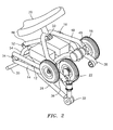
- Figure 1 is a rear perspective view of a personal vehicle with various frame coverings removed to expose the frame and features of the invention.
- Figure 2 is a rear perspective view of the vehicle shown in Figure 1, wherein the front and rear frame assemblies have been folded together.
- Figure 3 is an front perspective view of an embodiment of a personal vehicle using a front wheel motor drive and aspects of the invention.
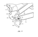
- Figure 4 shows an enlarged view of the connection between the front and rear frame assemblies of the vehicle of Figure 3.
- Figure 5 is a side view of the vehicle of Figure 4 wherein the frame assemblies are pivoted at a 90 degree angle with respect to one another.
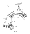
- Figure 6 is a side perspective view of the vehicle shown in Figures 4 and 5 wherein the front and rear frame assemblies are folded together and the seat support structure is collapsed onto the rear frame assembly.
- Figure 7 is a cross-sectional view of a portion of the front and rear frame assemblies showing details of the latch mechanism for locking and releasing the front and rear frame assemblies and seat support.
- Figure 8 is an external view of a portion of the front and rear frame assemblies showing the latch mechanism.
- Figure 9 is a cross-sectional perspective view of the latch mechanism with the frame assemblies in the collapsed position.
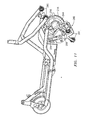
- Figure 10 is a side view of a collapsible vehicle frame having a pivotal rear transaxle on which are mounted the rear wheels and drive motors. One wheel has been removed to expose details of the axle.
- Figure 11 is a view of the frame of figure 10 showing the transaxle pivoted away from the rear frame assembly.
- Figure 12 is a view of a personal mobility vehicle with an extendable lift handle setting upright on its anti-tip rollers in its collapsed condition.
- Figure 13 is a view of the vehicle of Figure 12 being towed on the anti-tip rollers.
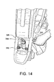
- Figure 14 is a view of a vehicle having a quick disconnect fitting between the steering tiller and the front steering wheel.
- FIG. 1 depicts a personal vehicle 10 from which various body covering panels have been removed to expose the frame and features of the invention.
- the vehicle 10 includes a rear frame assembly 12 and a front frame assembly 14.
- the rear frame assembly 12 supports two rear wheels 16.
- a seat support structure 18 is provided to support a seat 20 in an elevated position above the vehicle base. The seat may be detachable from the seat support.
- a front steering wheel 22 is supported by the front frame assembly 14.
- the steering wheel 22 is mounted in a wheel fork 24 which is rotationally supported in a collar 26 that is secured to the front frame assembly 14.
- a steering tiller 28 extends upwardly from the collar 26 to a handle bar 30.
- the tiller 28 may include an adjustment hinge 32 for adjusting the angle of the tiller, and thus the height and proximity of the handlebar 30 to the seat 20.
- the tiller 28 may further be length-adjustable by a telescoping section 33.
- the front and rear frame assemblies are pivotally connected to each other by hinges 34.
- a latch mechanism (which is more particularly discussed below in reference to more detailed drawings) is used to lock the front and rear frame assemblies in the fully-extended, normal operating position. When the latch is unlocked, the front and rear frame assemblies can be pivoted at the hinges 34 into a folded position in which the frame assemblies are positioned substantially adjacent to one another, effectively reducing overall length of the vehicle to about half.
- the front and rear frame assemblies 12, 14 may be formed of hollow tubular metal members welded together to form a rigid structure.
- the rear frame assembly 12 may extend beyond the rear wheels to mount rear anti-tip rollers 38.
- a pair of batteries 40 and an electric power controller 42 may be positioned below the seat support structure 18 and seat 20.
- a drive motor 44 is connected to one or both of the rear wheels 16.
- the vehicle 10 is shown in a partially collapsed condition wherein the front frame assembly is positioned closely adjacent the rear frame assembly 14 after they have been pivoted about the hinges 34.
- the steering tiller 28 has been placed in a collapsed condition by adjusting the angle of the adjustment hinge 32 and shortening the length by using the telescoping joint 33.
- the seat support structure may also collapse onto the rear frame assembly, as described hereafter.
- the seat support structure 18 may generally comprise a tubular front support member 46 aligned with the vehicle's longitudinal centerline and extending back from the front center of the rear frame assembly, in conjunction with a bipod support member 48 extending from an apex under the seat post to two projected ends 49, giving the seat support structure 18 a tripod configuration.
- the ends of the bipod member are pivotally connected to the rear frame near the rear wheels, such as by a rotational attachment to the wheel axles. This attachment of the distal ends of the seat support bipod member 48 allows the bipod member 48 to rotate from the upright riding position to a collapsed position.
- the front seat support member 46 is pivotally attached to the bipod member 48 and to the front frame assembly in a manner that allows the folding of the first and second frame assemblies to cause the seat support structure to collapse.
- the front support member 46 is pivotally attached to the bipod member 48 by a yoke and pin hinged connection 50.
- the opposite end of the front seat support member 46 is pivotally attached to a transverse member 54 of the front frame assembly 14 by a yoke and pin hinged connection 52.
- a lift handle 56 may be provided that extends upward from the transverse member 54 of the front frame assembly, or from some other convenient location near the hinged connection between the front and rear frame assemblies.
- FIGs 3 and 4 illustrate another embodiment of a personal utility vehicle 110, in which the drive motor is associated with the front steering wheel assembly 122. Like the previous embodiment, it has a rear frame assembly 112 and a front frame assembly 114, rear wheel assemblies 116, a seat support structure 118, a seat 120, a front steering wheel 122 and a steering tiller 128.
- This embodiment is depicted with its floor panels and other frame covers that were removed from the embodiment of Figure s 1 and 2, but it will be understood that the frames of both vehicles are largely the same.
- the rear frame assembly 112 is pivotably attached to the front frame assembly 114 by hinges 134.
- a latching mechanism 136 may be associated with this hinged connection.
- the floor panel and battery cover allow sufficient opening around the hinged connection 160 to allow the user manual access to a latch actuator 174 for the latching mechanism .
- the latch mechanism 136 of this embodiment is shown in Figure 7 (cross-section).
- the latch mechanism generally comprises an abutment fitting 168 at the end of the front seat support member 146 that attaches to a yoke 160 and pin 162 hinge on the'front frame 114.
- the fitting 168 can rotate around the hinge pin 162 to abut against the transverse crossing member 154 to prevent the front and rear frames from over-rotating past the aligned normal driving position.
- a retaining slot 176 in the fitting 168 is adapted to receive a locking pin 170, which is mounted in a sleeve 172 positioned within the crossing member 154.
- the sleeve also encloses a spring 178 to push the pin 170 into the slot 176.
- An activation lever 174 provided on the front frame assembly 114 is operatively connected to the locking pin such that operating the lever withdraws the pin 170 from the slot 176 and allows the fitting 168 to rotate around the hinge pin 162 when the front frame is lifted by the handle 164.
- the fitting 168 may have a second retaining slot 177 positioned to receive the locking pin 170 when the front and rear frame assemblies are folded together, thus locking them in that position until the actuation lever 174 is again moved to release the fitting 168 to rotate.
- FIG. 5 depicts the vehicle 110 partially folded.
- the latch actuator 174 was operated to unlatch the latch mechanism 136 and allow the abutment fitting 168 to rotate in the yoke 160. This unlatching also frees the frame hinges 134.
- the front frame assembly can be lifted by the handle 164 to start the folding at the hinges 134.
- the movement of the front frame cross member 154 away from the seat support assembly allows the seat support to collapse onto the rear frame assembly.
- the actuator lever 174 can be released while the frame assemblies are being folded, and the spring will lock the latch mechanism when the pin 170 is aligned with the slot 177, in the collapsed position shown in Figures 6 and 9.
- the steering tiller 128 can be collapsed toward the front frame assembly and shortened, as shown in Figure 6, by loosening and adjusting the angle of the adjustment hinge 132 and shortening the length by using the telescoping joint 133.
- latching mechanisms that could be used instead of the locking pin and abutment fitting with slots as descried in this embodiment.
- the invention is not intended to be limited by the type of latching mechanism.
- FIGS 10 and 11 depict another embodiment of a collapsible vehicle wherein the rear wheels 216, drive motor(s) and anti-tip rollers are mounted on a transaxle assembly 280 that is pivotally connected to the rear frame assembly, in which the transaxle can be unlatched and pivoted into the rear frame assembly to reduce the overall profile.
- the rear frame assembly 212 has on each side a urethane mounting block 282 to which an end 264 of the transaxle assembly is pivotally mounted.
- the rear wheels 216 and motor(s) 244 are mounted on a section of the transaxle axle assembly.
- the rear frame has a semi-circular channel 286 on each side to receive a hard rubber shock absorber 288 of the transaxle assemble when the rear wheels are resting on the ground and the front and rear frame assemblies are aligned in the normal use position.
- the transaxle may be locked in this position by any appropriate locking mechanism, such as intermeshing teeth discs 290, 291 on the rear frame and on the axle, as depicted in figure 11.
- the axle assembly may also have rear extensions on which are mounted the anti-tip rollers. When the intermeshing lock discs are loosened and moved apart so that the teeth no longer mesh, the transaxle assembly 280 can be pivoted to rest against the underside of the rear frame 212.
- the lift handle 364 may have extended forks in tubes 390 in the rear frame assembly 354. After the vehicle is folded into its compact profile, the handle extension can be drawn out to full length and the handle 364 can be used to tow the folded vehicle on the anti-tip rollers, as shown in Figure 13.
- the steering tiller 328 may be pivotally attached 392 to the front frame assembly and also be capable of easy disconnect from the front steering wheel assembly, as by the removable pin connection 394, 396 shown in Figure 14. Once disconnected from the front wheel assembly 322, but still attached to the front frame assembly, the tiller 328 can be collapsed into the front frame assembly to provide a very compact profile for storage or transport.
Applications Claiming Priority (2)
| Application Number | Priority Date | Filing Date | Title |
|---|---|---|---|
| US50949403P | 2003-10-08 | 2003-10-08 | |
| US509494P | 2003-10-08 |
Publications (2)
| Publication Number | Publication Date |
|---|---|
| EP1522489A2 true EP1522489A2 (de) | 2005-04-13 |
| EP1522489A3 EP1522489A3 (de) | 2006-08-23 |
Family
ID=34312491
Family Applications (1)
| Application Number | Title | Priority Date | Filing Date |
|---|---|---|---|
| EP04256226A Withdrawn EP1522489A3 (de) | 2003-10-08 | 2004-10-08 | Zuzammenklappbares Fahrzeug |
Country Status (3)
| Country | Link |
|---|---|
| US (1) | US20050077097A1 (de) |
| EP (1) | EP1522489A3 (de) |
| CA (1) | CA2484434A1 (de) |
Cited By (9)
| Publication number | Priority date | Publication date | Assignee | Title |
|---|---|---|---|---|
| EP1874617A2 (de) * | 2005-04-29 | 2008-01-09 | Hartmut Hubert | Steckverbinderstützwinkel für ein fahrzeug |
| WO2009024808A1 (en) * | 2007-08-22 | 2009-02-26 | Cain, Ben | Personal mobility vehicle |
| CN103387028A (zh) * | 2012-07-19 | 2013-11-13 | 亚伯拉罕·尼诺·瑞森伯格 | 机动车 |
| CN103950493A (zh) * | 2013-11-22 | 2014-07-30 | 蒋晶 | 一种折叠式自动车 |
| CN104085483A (zh) * | 2014-06-26 | 2014-10-08 | 丹阳星锐康复器械有限公司 | 可折叠电动三轮车 |
| CN104228948A (zh) * | 2013-06-11 | 2014-12-24 | 福特全球技术公司 | 折叠车辆 |
| CN105050891A (zh) * | 2013-03-11 | 2015-11-11 | N.G.M.有限公司 | 支撑系统和配有该支撑系统的轮车 |
| CN106275200A (zh) * | 2016-09-28 | 2017-01-04 | 詹伟(上海)机电有限公司 | 一种便携三轮车 |
| US9809273B2 (en) | 2014-02-12 | 2017-11-07 | Royalty Bugaboo Gmbh | Foldable vehicle |
Families Citing this family (18)
| Publication number | Priority date | Publication date | Assignee | Title |
|---|---|---|---|---|
| US7967095B2 (en) * | 2003-10-08 | 2011-06-28 | Pride Mobility Products Corporation | Collapsible vehicle |
| US7278507B2 (en) * | 2004-04-23 | 2007-10-09 | Bruce Walworth | Collapsible personal transportation vehicle |
| WO2007128124A1 (en) * | 2006-05-08 | 2007-11-15 | Lakehead University | Powered foldable scooter |
| FR2940241B1 (fr) * | 2008-12-23 | 2011-01-21 | Xor Motors | Structure de repliement d'un motocycle avec verrouillage rapide et pratique |
| US8167074B1 (en) * | 2010-03-17 | 2012-05-01 | Joseph Tsiyoni | Three-wheel, driver's stand-up, portable, leverless vehicle, with foot brake lever and connecting method thereoff |
| US8511705B2 (en) * | 2011-01-28 | 2013-08-20 | Chichun Wu | Wheel automatic adjustment mechanism and foldable motorized vehicle having same |
| CN202029936U (zh) * | 2011-01-28 | 2011-11-09 | 武济群 | 安装支架 |
| EP2673185B1 (de) * | 2011-02-11 | 2018-08-01 | Trikelet B.V. | Zusammenklappbarer motorroller |
| US8714292B1 (en) * | 2012-09-19 | 2014-05-06 | Keith K. Wong | Motorized wheeled chair assembly |
| CN102951236B (zh) * | 2012-11-02 | 2015-04-29 | 武济群 | 折叠车架 |
| US9301893B1 (en) * | 2015-06-08 | 2016-04-05 | Energy Control Limited | Foldable scooter frame |
| CN109070962B (zh) * | 2016-03-22 | 2021-07-23 | 福特全球技术公司 | 机动运输踏板车 |
| CN106184549B (zh) * | 2016-07-21 | 2018-11-09 | 东莞威信运动用品有限公司 | 折叠车架 |
| CN110395343A (zh) * | 2018-04-24 | 2019-11-01 | 南京金百合医疗器械有限公司 | 手动电动折叠代步车 |
| TWM582476U (zh) * | 2018-11-20 | 2019-08-21 | 建迪企業股份有限公司 | 一種可自動收折之電動車 |
| US11485444B2 (en) * | 2020-04-30 | 2022-11-01 | Dennis Li | Luggage scooter |
| US11147209B1 (en) | 2021-04-01 | 2021-10-19 | Ataco Steel Products Corp. | Riding lawn mower |
| USD934956S1 (en) * | 2021-05-23 | 2021-11-02 | Raymond Rhamey | Folding electric personal utility scooter |
Family Cites Families (21)
| Publication number | Priority date | Publication date | Assignee | Title |
|---|---|---|---|---|
| US3004619A (en) * | 1958-08-21 | 1961-10-17 | Tradall Sa | Collapsible motor vehicle |
| US3710965A (en) * | 1970-12-21 | 1973-01-16 | J Joosten | Material handling vehicle and method of storing same |
| US4087108A (en) * | 1976-09-28 | 1978-05-02 | General Motors Corporation | Cambering vehicle with trailing arms interconnected by spur gearing |
| GB1571849A (en) * | 1977-03-28 | 1980-07-23 | Tomy Kogyo Co | Folding bicycle |
| US4111447A (en) * | 1977-03-29 | 1978-09-05 | Tomy Kogyo Co., Ltd. | Folding bicycle |
| US4462606A (en) * | 1981-02-12 | 1984-07-31 | Hon Corporation International | Foldable and portable vehicle |
| US4570739B1 (en) * | 1983-09-29 | 1994-04-19 | Burke Inc | Personal mobility vehicle |
| GB9014314D0 (en) * | 1990-06-27 | 1990-08-15 | Vessa Ltd | Wheeled vehicle |
| US5277267A (en) * | 1991-05-20 | 1994-01-11 | Tiffany Charles E | Collapsible portable golf cart |
| US5240086A (en) * | 1992-05-08 | 1993-08-31 | Electric Mobility Corp. | Removable drive train from frame of a personal vehicle |
| US5467838A (en) * | 1994-01-19 | 1995-11-21 | Wu; Donald P. H. | Automatically deployable vehicle stabilization system |
| CA2421859A1 (en) * | 1996-10-11 | 1998-04-23 | Wheelchair Carrier, Inc. | Lightweight motorized wheelchair |
| GB2332403A (en) * | 1997-11-05 | 1999-06-23 | Malcolm Edward Solomon Peake | A personal vehicular accessory |
| IT1299007B1 (it) * | 1998-04-02 | 2000-02-07 | Francesco Mombelli | Bicicletta compattabile nel volume delle due ruote affiancate |
| CN2335876Y (zh) * | 1998-06-05 | 1999-09-01 | 张关礼 | 缩折轻便自行车 |
| US6854551B2 (en) * | 2000-09-25 | 2005-02-15 | Warren R. Wisecarver | Collapsible vehicle |
| ITRN20000048A1 (it) * | 2000-12-06 | 2002-06-06 | Unit S R L | Contenitore trasportabile manualmente su ruote. |
| FR2818611B1 (fr) * | 2000-12-27 | 2003-04-04 | Henri Bigot | Bicyclette pliable |
| WO2003037678A2 (en) * | 2001-10-26 | 2003-05-08 | Electric Mobility Corporation | Foldable personal mobility vehicle |
| JP3749232B2 (ja) * | 2002-04-01 | 2006-02-22 | 三洋電機株式会社 | 段差昇降方法、台車及び車椅子 |
| US6739669B2 (en) * | 2002-05-23 | 2004-05-25 | Tzora Active Systems Ltd. | Foldable armrest for a seat having a collapsible back |
-
2004
- 2004-10-07 US US10/960,742 patent/US20050077097A1/en not_active Abandoned
- 2004-10-08 CA CA002484434A patent/CA2484434A1/en not_active Abandoned
- 2004-10-08 EP EP04256226A patent/EP1522489A3/de not_active Withdrawn
Non-Patent Citations (1)
| Title |
|---|
| None |
Cited By (17)
| Publication number | Priority date | Publication date | Assignee | Title |
|---|---|---|---|---|
| EP1874617A4 (de) * | 2005-04-29 | 2009-05-27 | Hartmut Hubert | Steckverbinderstützwinkel für ein fahrzeug |
| EP1874617A2 (de) * | 2005-04-29 | 2008-01-09 | Hartmut Hubert | Steckverbinderstützwinkel für ein fahrzeug |
| WO2009024808A1 (en) * | 2007-08-22 | 2009-02-26 | Cain, Ben | Personal mobility vehicle |
| US9265675B2 (en) | 2012-07-19 | 2016-02-23 | Moving Life Ltd. | Motorized vehicle |
| CN103387028A (zh) * | 2012-07-19 | 2013-11-13 | 亚伯拉罕·尼诺·瑞森伯格 | 机动车 |
| WO2014013486A2 (en) * | 2012-07-19 | 2014-01-23 | Moving Life Ltd. | Motorized vehicle |
| WO2014013486A3 (en) * | 2012-07-19 | 2014-05-22 | Moving Life Ltd. | Motorized vehicle |
| EP3354549A1 (de) * | 2012-07-19 | 2018-08-01 | Moving Life Ltd. | Motorisiertes fahrzeug |
| CN103387028B (zh) * | 2012-07-19 | 2015-11-25 | 亚伯拉罕·尼诺·瑞森伯格 | 机动车 |
| CN105050891B (zh) * | 2013-03-11 | 2018-03-16 | N.G.M.有限公司 | 支撑系统和配有该支撑系统的轮车 |
| CN105050891A (zh) * | 2013-03-11 | 2015-11-11 | N.G.M.有限公司 | 支撑系统和配有该支撑系统的轮车 |
| CN104228948A (zh) * | 2013-06-11 | 2014-12-24 | 福特全球技术公司 | 折叠车辆 |
| CN104228948B (zh) * | 2013-06-11 | 2018-01-05 | 福特全球技术公司 | 折叠车辆 |
| CN103950493A (zh) * | 2013-11-22 | 2014-07-30 | 蒋晶 | 一种折叠式自动车 |
| US9809273B2 (en) | 2014-02-12 | 2017-11-07 | Royalty Bugaboo Gmbh | Foldable vehicle |
| CN104085483A (zh) * | 2014-06-26 | 2014-10-08 | 丹阳星锐康复器械有限公司 | 可折叠电动三轮车 |
| CN106275200A (zh) * | 2016-09-28 | 2017-01-04 | 詹伟(上海)机电有限公司 | 一种便携三轮车 |
Also Published As
| Publication number | Publication date |
|---|---|
| EP1522489A3 (de) | 2006-08-23 |
| US20050077097A1 (en) | 2005-04-14 |
| CA2484434A1 (en) | 2005-04-08 |
Similar Documents
| Publication | Publication Date | Title |
|---|---|---|
| EP1522489A2 (de) | Zuzammenklappbares Fahrzeug | |
| US10479436B2 (en) | Collapsible vehicle | |
| US7451848B2 (en) | Foldable personal mobility vehicle | |
| CN103387028B (zh) | 机动车 | |
| US3912032A (en) | Wheelchair-attachable powered unit | |
| US8276935B2 (en) | Foldable stroller | |
| US7766359B2 (en) | Trailer/jogger combination | |
| US7125080B1 (en) | Foldable armrest for chair | |
| US6991243B2 (en) | Platform scooter for larger children and handicapped persons | |
| US5927730A (en) | Scooter cart | |
| US20060108766A1 (en) | Folding bicycle trailer | |
| US7669881B2 (en) | Collapsible conveyance folding transport chair folding wheelchair | |
| JPH0374578B2 (de) | ||
| EP1730010A2 (de) | Zusammenklappbares beförderungsmittel, faltbarer transportstuhl, faltbarer rollstuhl | |
| US5975559A (en) | Urban and all-terrain stroller | |
| US11220282B2 (en) | Stroller accessory and double stroller assembly | |
| WO2022224238A1 (en) | Scooter convertible to push-cart | |
| EP3845443B1 (de) | Zusammenklappbarer roller | |
| CN100408418C (zh) | 折叠自行车 | |
| US8998257B2 (en) | Lift system and apparatus for use with motorized tricycles | |
| CN215663810U (zh) | 一种折叠代步车 | |
| CN210027757U (zh) | 折叠式三轮车 | |
| IL292295A (en) | Scooter convertible to push-cart | |
| NZ730844B2 (en) | A dual configuration portable wheelchair | |
| GB2419329A (en) | Folding collapsible golf cart |
Legal Events
| Date | Code | Title | Description |
|---|---|---|---|
| PUAI | Public reference made under article 153(3) epc to a published international application that has entered the european phase |
Free format text: ORIGINAL CODE: 0009012 |
|
| AK | Designated contracting states |
Kind code of ref document: A2 Designated state(s): AT BE BG CH CY CZ DE DK EE ES FI FR GB GR HU IE IT LI LU MC NL PL PT RO SE SI SK TR |
|
| AX | Request for extension of the european patent |
Extension state: AL HR LT LV MK |
|
| PUAL | Search report despatched |
Free format text: ORIGINAL CODE: 0009013 |
|
| AK | Designated contracting states |
Kind code of ref document: A3 Designated state(s): AT BE BG CH CY CZ DE DK EE ES FI FR GB GR HU IE IT LI LU MC NL PL PT RO SE SI SK TR |
|
| AX | Request for extension of the european patent |
Extension state: AL HR LT LV MK |
|
| AKX | Designation fees paid |
Designated state(s): AT BE BG CH CY CZ DE DK EE ES FI FR GB GR HU IE IT LI LU MC NL PL PT RO SE SI SK TR |
|
| STAA | Information on the status of an ep patent application or granted ep patent |
Free format text: STATUS: THE APPLICATION IS DEEMED TO BE WITHDRAWN |
|
| 18D | Application deemed to be withdrawn |
Effective date: 20070501 |