EP1522357A2 - Dispositif de fermeture pour des électrodes - Google Patents
Dispositif de fermeture pour des électrodes Download PDFInfo
- Publication number
- EP1522357A2 EP1522357A2 EP04021849A EP04021849A EP1522357A2 EP 1522357 A2 EP1522357 A2 EP 1522357A2 EP 04021849 A EP04021849 A EP 04021849A EP 04021849 A EP04021849 A EP 04021849A EP 1522357 A2 EP1522357 A2 EP 1522357A2
- Authority
- EP
- European Patent Office
- Prior art keywords
- welding
- electrode
- force
- axis
- welding device
- Prior art date
- Legal status (The legal status is an assumption and is not a legal conclusion. Google has not performed a legal analysis and makes no representation as to the accuracy of the status listed.)
- Granted
Links
Images


Classifications
-
- B—PERFORMING OPERATIONS; TRANSPORTING
- B23—MACHINE TOOLS; METAL-WORKING NOT OTHERWISE PROVIDED FOR
- B23K—SOLDERING OR UNSOLDERING; WELDING; CLADDING OR PLATING BY SOLDERING OR WELDING; CUTTING BY APPLYING HEAT LOCALLY, e.g. FLAME CUTTING; WORKING BY LASER BEAM
- B23K11/00—Resistance welding; Severing by resistance heating
- B23K11/30—Features relating to electrodes
- B23K11/31—Electrode holders and actuating devices therefor
- B23K11/314—Spot welding guns, e.g. mounted on robots
-
- H—ELECTRICITY
- H01—ELECTRIC ELEMENTS
- H01H—ELECTRIC SWITCHES; RELAYS; SELECTORS; EMERGENCY PROTECTIVE DEVICES
- H01H11/00—Apparatus or processes specially adapted for the manufacture of electric switches
- H01H11/04—Apparatus or processes specially adapted for the manufacture of electric switches of switch contacts
Definitions
- the present invention relates to a welding device with at least two welding electrodes.
- a welding device with at least two welding electrodes.
- the Welding device which the at least two substantially opposite each other Defining welding electrodes between them comprises the Welding device, a power source and the force of the power source transmitting power transmission mechanism. From the welding electrodes at least one electrode is provided by one of the power source and transmitted to it by the power transmission mechanism Force toward the other electrode to and from this movable.
- Such a welding device is known from DE 197 55 166 A1.
- the welding device shown there has one as a power source Shaft rotating eccentric cam and as a power transmission mechanism a compression spring used as a welding gap closing spring.
- the Closing spring is at one end to one of the eccentric cam jacket surface adjoining pestle and at its other end at one supported a pivot axis swivel electrode arm.
- the welding electrode arm engages as a welding gap opening spring used further compression spring, which at the Sch spaelektrodenarm unloaded or slightly loaded closing spring in one in the direction of Magnification of the welding gap width biasing opening direction pretensions.
- Another critical point of the welding device of the prior Technique is the influence of friction on the movement of the welding electrode arm, especially for movements with a small stroke, such as Setzmonyen the Sch spaelektrodenarms during melting of Represent welding lugs on one of the parts to be joined or on both parts to be joined.
- a welding device specify the type mentioned, in which the movement the welding electrodes at a welding gap reduction under possible low mechanical stress on the joining part, especially in a phase in which a touch contact between the electrode and the Joining part is produced.
- the increased sensitivity miniaturized adherends to mechanical loads are produced.
- a generic Welding device solved which at least one lever mechanism as the power transmission mechanism, wherein the lever mechanism a first link system, which at a respect resting parts of the welding device fixed articulation about a frame rotation axis is rotatable, and wherein the lever mechanism is still a second link system, which at a first articulation point the first link system rotatably articulated about a first axis of rotation and rotatable at a second articulation about a second axis of rotation with the movable electrode is connected.
- lever mechanism described above is not excluded that in addition to the mentioned Anschorten more Anschorte available are. Rather, the description of the lever mechanism is to be understood in such a way that at least the mentioned Anschorte should be present.
- connection to the movable electrode does not mean necessarily a direct linkage to the movable electrode.
- the rotatable connection can also have one with the movable one Implemented electrode connected motion transmitting device part be.
- the lever mechanism a toggle mechanism, wherein the frame axis of rotation, the first and the second axis of rotation in pairs substantially lie parallel to each other.
- the substantially parallel arrangement of Rotary axes to each other ensures easily calculable ratios as well as for a lower operating wear and thus for a long service life and low-friction operation of the welding device.
- the second link system only consist of a single handlebar.
- the second comprises Handlebar system, however, a plurality of links, which essentially have a common first and a common second axis of rotation and spaced apart in the direction of the second axis of rotation are.
- this embodiment allows a favorable symmetrical force and movement initiation and creates the condition for a play-free displacement of the movable welding electrode.
- the first Handlebar system comprise a plurality of links, which are substantially have a common frame rotation axis and in the direction of Frame pivot axis are arranged at a distance from each other.
- the second one first link system each preferably two links.
- the parts to be joined discussed here are components with thickness dimensions in the range of hundredths or tenths of a millimeter.
- a for a precise positioning helpful play-free movement of the movable welding electrode to the other electrode to or from this way can be achieved by forming the second pivot point such be that from the second link system to the electrode out in the direction of movement the electrode running force and, at least temporarily, beyond that in the direction of the second axis of rotation, each other opposite forces are transferable.
- the opposing forces can be very simple Way be caused by the fact that the second articulation is formed such that on one side: handlebar system side or electrode side, a projection with conical lateral surface is provided, which with a corresponding inclined, preferably a complementary conical Boundary surface of one provided on the other side Coupling recess at least temporarily in investment engagement stands.
- the opposing forces cause a strain the at least one movable electrode with respect to the second linkage system, so that they are essentially free of side deviations in the Movement direction is displaced.
- the thus-stressed welding electrode can due to thereby essentially avoided side deviations with great accuracy be arranged at the joint, which in turn leads to a improved dimensional accuracy of the welding results.
- the coupling recess as Slot formed and arranged such that the longitudinal direction of the slot in a welding ready electrode position substantially in the direction of movement of the movable electrode. At a such arrangement allows the slot in the electrode position ready for welding, i.e. when the electrode active surface rests on the adherend, that no more pressure forces from the lever system to the electrode and thus act on the joining part.
- such a trained slot allows a low-friction Setting the at least one movable electrode during the Welding, such as caused by a melting of the component itself or provided on the support object welding warts.
- the at least one movable welding electrode can according to a Development of the invention linearly displaceable on the welding device be arranged. However, it can also be in the state of the art proven way at a pivot point about an electrode axis of rotation be rotatably supported by a Sch spaelektrodenarm connected to the pivot bearing. Through the welding electrode arm is at sufficient Sch spaelektrodenarmin and only small change in the welding gap a quasi-linear displacement of movable electrode achieved without a complicated linear guide is required.
- the movable electrode on a Welding electrode arm is particularly suitable for low-friction operation favorable when the second axis of rotation, preferably also the first axis of rotation and the frame rotation axis, to the electrode rotation axis substantially is parallel.
- the welding electrode arm be arranged such that it other device parts of the welding device, especially the transport device, does not bother.
- One for collision avoidance offset in the direction of the electrode axis of rotation arrangement The welding electrode arm may be undesirable Torsion of the welding electrode arm about the longitudinal axis of the welding electrode arm. This distortion can be prevented when the welding electrode arm is two in the direction of the axis of rotation of the electrode having spaced apart carriers.
- Important Welding device parts with which a collision can be avoided should, according to an embodiment of the invention between the be provided both carriers. For reasons symmetriescher force and Initiation of movement are the carriers in relation to the one associated with it movable welding electrode preferably arranged symmetrically. Around a relative movement of the two carriers to each other to avoid According to the invention, both carriers rotatably with a common rotary shaft be connected.
- the power source of the welding device can according to an advantageous Alternative to the present invention, a double-acting power source so that with it the welding electrodes face each other and from each other can be moved away.
- a double-acting power source so that with it the welding electrodes face each other and from each other can be moved away.
- Welding devices part of a larger system, which clocked works, the clock given by eccentric cam as sources of power becomes.
- the clock given by eccentric cam as sources of power becomes.
- the welding device has a force element which is the movable one Electrode in one direction: weld gap enlargement or Weld gap size reduction, with force applied to the necessary Provide force for a change in the welding gap width in this direction.
- a Change in the welding gap width in the opposite direction Being able to reach direction is the force element through the power source surmountable.
- the power source basically also on the second handlebar system for force and movement initiation attack.
- the force element can also be on one of the handlebar systems, due to the more favorable movement conditions preferably on the first handlebar system, force transmitting attack.
- a favorable spatial separation of force or movement initiation in the first handlebar system and power or movement derivation from the first in the second link system can according to a development of the invention be achieved when the first link system at least one Winkellenker with two legs enclosing a predetermined angle wherein the one leg is a force introduction area for introduction of force of the power source as well as an attack location of the force element and wherein on the second leg of the first articulation point for articulation is formed of the second link system.
- the welding device comprises a force device, which has a force acting in the direction of the welding gap reduction the movable electrode, preferably on the welding electrode arm, exercises.
- a force device which has a force acting in the direction of the welding gap reduction the movable electrode, preferably on the welding electrode arm.
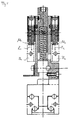
- a welding system is generally designated 10.
- the welding system 10 includes a contact belt feed unit 12, a contact part separation unit 14, a transport device 16 and a welding device 18th
- a in Fig. 1 only indicated by dashed line contact strip 20th runs in the drawing plane of Fig. 1 of the contact band feed unit 12 clocked driven to the contact part separation unit 14.
- In the contact part separation unit 14 are by shearing off the contact band Contact parts defined length separated. These contact parts are in the Transport device 1 6 of an assembly 22 comprising a holding and a release device received in a holding device receiving position and transported to a holding device dispensing position.
- the welding device 18 includes a relative to a device frame the welding device fixed bottom welding electrode 24 and a rotatable about an electrode axis of rotation E movable welding electrode 26.
- the movable welding electrode 26 is above a welding electrode arm 28 connected to the pivot bearing about the electrode axis of rotation E. and in the direction of the double arrow K on the electrode 24 to and from this way movable.
- the welding electrode arm 28 is only partially, partly by dashed line, shown.
- the clock for the contact band feed unit 12 and for lifting and Lowering of the movable welding electrode 26 is indicated by a first eccentric cam 30 on a spring force on the eccentric cam lateral surface Transfer 30a adjacent first plunger 32.
- a clock for moving the transport device 16 via a second eccentric cam 34 on a by spring force on the eccentric cam lateral surface Transfer 34a adjacent second plunger 36 is the short leg 38a of an L-shaped lever 38 rotatably mounted, the long leg 38b a sliding movement the assembly 22 during up and down movement of the second plunger 36th causes.
- the assembly 22 or a rotatably connected with her component comprises a Zahnteilnik, which during the sliding movement on a rack bar, so that the assembly 22 a combined Moving and rotating movement performs. This allows the overcoming long distances between holding device receiving position and holding device delivery position.
- From the first plunger 32 is about a plate nut 40 movement on a first link system 42 transmitted. From the first link system 42 is via a second linkage system 44 the movement to the welding electrode arm 28 transmitted.
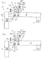
- Fig. 2 A more detailed description of Fig. 2 can be seen. First, will however, the transport device 16 for feeding the welding device 18 with components to be joined (parts to be joined).
- a longitudinal end of the long leg 38b of the L-shaped lever 38 is rotatably received in a sliding element 46, which along a 2 arranged guide rod 48 parallel to the plane of FIG slidably arranged.
- a connecting pin 50 and a Connecting rivet 52 which rotatably with the rotatable in the sliding element 46 mounted connecting pin 50 is connected, are the assembly 22 and a rolling part 54 connected to the displacement element 46.
- the assembly 22, comprising the holding device 56 and the Release means 58, and the rolling member 54 are for common movement connected with each other.
- Retainer dispensing position is by depressing the plunger 36th the L-shaped lever is rotated by an angle ⁇ counterclockwise. From the longitudinal end of the long leg 38b, the sliding element 46 along the guide rod 48 taken to the right.
- the Abroll part 54 on whose weg mandem of the holding device 56 Longitudinal end 54a a toothing pitch circle is formed, is first moved linearly to the right until the toothing meshes with an in Fig. 2, not shown rack passes. From the preparation of the toothing intervention a sliding movement of the assembly 22 and the rolling part 54 together with the displacement element 46, the one Pivoting 180 ° about the central axis 50a of the connecting bolt 50 is superimposed around.
- the assembly 22 further includes a biasing compression spring 60, which the holding device 56 with respect to the release device 58 biases in a position in which the release device 58 is retracted with respect to the holding device 56.
- the welding electrode arm 28 itself is not shown in Fig. 2.
- a closing force S on a roller 64 which rotatably disposed on a first leg 42 a of the first linkage system 42 is.
- the opening force acts on the first leg 42a O in the opposite direction.
- the opening force becomes O generated by squeezing the welding gap opening pressure spring 66.
- the welding gap opening pressure spring 66 is in its spring hardness in such a way chosen to be able to lift the welding electrode arm 28, however the first eccentric cam 30 is compressible.
- the first link system is a stationary or transport device rack Frame pivot axis G rotatable at a fixed pivot point 68 am Device rack articulated.
- a second leg 42b which has an angle y with includes the first leg 42a is at a first pivot point 70 to a first axis of rotation H rotatably articulated to the second link system 44.
- the second Handlebar system 44 rotatable about a second axis of rotation J with the in Fig. 2 not shown movable electrode 62 connected.
- a slot 74 On the second Anschort 72 is formed in the second link system 44, a slot 74, which will be discussed below.
- the Slot 74 may also be formed on the welding electrode arm 28 at which the second link system 44 at the second pivot point 72 directly is articulated.
- Fig. 3 is a section along the line V-V in Fig. 2 is shown.
- Fig. 5 is both the welding gap opening compression spring 66 and its spring abutment as well as the first and second linkage system 42 and 44 cut shown.
- the first link system 42 consists of two links 42 1 and 42 2 , which are connected to each other via a common cross member 98. On the Traverse 98, the roller 64 is rotatably supported.
- the links 42 1 and 42 2 of the first linkage system 42 are rotatably connected to the second linkage system 44 about the first axis of rotation H.
- the second link system 44 also includes a first link 44 1 and a second link 44 2 .
- the first link 44 1 of the second link system is articulated to the handlebar 42 1 of the first link system 42
- the second link 44 2 of the second link system is articulated to the handlebar 42 2 of the first link system 42.
- both first articulation points 70 1 and 70 2 have a common first axis of rotation H.
- the articulation of the second Lenkersystsems 44 on the first link system 42 is effected by bolts 100, which allow a relative rotation between the first and second link system.
- the Sch hasslektrodenarm 28 is formed in the example shown here by two substantially mutually parallel support 28 1 and 28 2 , which are connected to a common, not shown rotating shaft and rotate without the possibility of relative rotation to each other about the electrode axis of rotation E.
- the shafts of tapered head rivets 104 are added in the through holes 102 1 and 102 2 in the carriers 28 1 and 28 2 .
- the conical head 106 of the conical head rivet 104 has a frustoconical head, which extends into the slot 74 of the second link system 44.
- the slots are also marked with subscript numbers to identify the assignment to the respective links of the second link system 44.
- the slots 74 1 and 74 2 of the second link system 44 have according to the cone opening angle of the conical head 106 inclined side surfaces 74 b 1 and 74 b 2 , against which the outer surface of the conical head 106 is applied. Due to this design it is achieved that when the carrier 28 1 and 28 2 of the swing arm 28 via the conical heads 106 on the inclined side surfaces 74b 1 and 74b 2 abut the elongated holes 74, not only a force in the direction of movement of the welding electrode 26, but Also, a force in the direction of arrows B 1 and B 2 is transmitted to the respective carrier 28 1 and 28 2 , so that the carrier 28 1 and 28 2 pushed away from each other under the action of force and braced, resulting in a substantially backlash-free displacement of the carrier allowed. This allows a very accurate positioning of the welding electrode.
- Fig. 4 is a section along the line VI-VI in Fig. 2 is shown. What interests substantially only the force applied to the carrier 28 1 and 28 2 by welding gap-closing pressure springs 108 1 and 108. 2 Each of these welding gap-closing compression springs 108 1 and 108 2 exerts a force Z 1 or Z 2 on their respective assigned carrier 28 1 or 28 2 , which ensures a defined closing force in the welding ready position of the welding device.
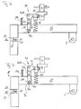
- Fig. 5a the welding device 18 is opened, i. with large welding gap width shown.
- a component 84 is arranged in the welding gap 25 in the welding gap 25 in the welding gap 25 in the welding gap 25 in the welding gap 25 in the welding gap 25 in the welding gap 25 in the welding gap 25 in the welding gap 25 in the welding gap 25 in the welding gap 25 in the welding gap 25 in the welding gap 25 in the welding gap 25 in the welding gap 25 in the welding gap 25 is arranged.
- a position is reached, wherein the electrode active surface 26a rests on the component 84, so that further closing of the welding gap 25 is mechanically inhibited by the component 84.
- the welding gap closing pressure spring 108 still provides for a concern of Kegelkopfniets 104 at the slot bottom 74a.
- Fig. 5d the welding device 18 is in a completely ready for welding Shown position.
- the lever mechanism 41 is in extended Condition, which due to the movement inhibition in the closing direction of the welding electrode arm 28 through the member 84 causes the Kegelkopfniet 104 no longer rests on the slot base 74a and in the direction of movement the electrode 26 from the lever mechanism 41 no force the welding electrode arm 28 can be transmitted. Because the power of Weld gap opening pressure spring 66 through the first eccentric cam 30th and the plate nut 40 is overcome, determined solely by the welding gap closing compression spring 108 on the component 84 by the movable electrode 26 applied force.
- This design of completely ready for welding Position has the further advantage that a low-friction setting of Welding electrode arm 28 is possible during welding.
Landscapes
- Engineering & Computer Science (AREA)
- Robotics (AREA)
- Mechanical Engineering (AREA)
- Manufacturing & Machinery (AREA)
- Resistance Welding (AREA)
- Discharge Heating (AREA)
- Superconductors And Manufacturing Methods Therefor (AREA)
- Compression, Expansion, Code Conversion, And Decoders (AREA)
- Oscillators With Electromechanical Resonators (AREA)
- Medicines Containing Material From Animals Or Micro-Organisms (AREA)
Priority Applications (1)
| Application Number | Priority Date | Filing Date | Title |
|---|---|---|---|
| PL04021849T PL1522357T3 (pl) | 2003-10-10 | 2004-09-14 | Urządzenie do zamykania elektrody |
Applications Claiming Priority (2)
| Application Number | Priority Date | Filing Date | Title |
|---|---|---|---|
| DE10347074A DE10347074A1 (de) | 2003-10-10 | 2003-10-10 | Elektrodenschließmechanikvorrichtung |
| DE10347074 | 2003-10-10 |
Publications (3)
| Publication Number | Publication Date |
|---|---|
| EP1522357A2 true EP1522357A2 (fr) | 2005-04-13 |
| EP1522357A3 EP1522357A3 (fr) | 2006-05-31 |
| EP1522357B1 EP1522357B1 (fr) | 2008-07-16 |
Family
ID=34306350
Family Applications (1)
| Application Number | Title | Priority Date | Filing Date |
|---|---|---|---|
| EP04021849A Expired - Lifetime EP1522357B1 (fr) | 2003-10-10 | 2004-09-14 | Dispositif de fermeture pour des électrodes |
Country Status (5)
| Country | Link |
|---|---|
| EP (1) | EP1522357B1 (fr) |
| AT (1) | ATE401149T1 (fr) |
| DE (2) | DE10347074A1 (fr) |
| ES (1) | ES2309430T3 (fr) |
| PL (1) | PL1522357T3 (fr) |
Cited By (1)
| Publication number | Priority date | Publication date | Assignee | Title |
|---|---|---|---|---|
| CN115213570A (zh) * | 2022-07-09 | 2022-10-21 | 广东国玉科技有限公司 | 用于电阻料带的光纤激光切割设备 |
Families Citing this family (1)
| Publication number | Priority date | Publication date | Assignee | Title |
|---|---|---|---|---|
| DE102011077754A1 (de) | 2011-06-17 | 2012-12-20 | Otto Bihler Handels-Beteiligungs-Gmbh | Schweißvorrichtung mit Wärmestrahlungsdetektion und Verfahren zur Überwachung des Schweißvorgangs |
Family Cites Families (6)
| Publication number | Priority date | Publication date | Assignee | Title |
|---|---|---|---|---|
| FR622674A (fr) * | 1926-02-06 | 1927-06-03 | Perfectionnements aux machines à souder électriques | |
| DE712053C (de) * | 1939-05-26 | 1941-10-10 | Aeg | Vorrichtung zum UEbertragen des Druckes vom Antrieb auf die bewegliche Elektrode beielektrischen Widerstandspunkt- oder Nahtschweissmaschinen |
| US3745842A (en) * | 1971-11-02 | 1973-07-17 | J Brems | Force transferring and multiplying system |
| US5046706A (en) * | 1988-05-10 | 1991-09-10 | Peninsular, Inc. | Power clamp |
| JPH0236083A (ja) * | 1988-07-22 | 1990-02-06 | Kiyouhou Seisakusho:Kk | パンタグラフ型ロボットアーム |
| DE19755166A1 (de) * | 1997-12-11 | 1999-06-17 | Bihler Otto Handels Beteiligungs Gmbh | Einrichtung und Verfahren zum Anbringen eines Kontaktmetallteils an einem Trägerteil durch Schweißen |
-
2003
- 2003-10-10 DE DE10347074A patent/DE10347074A1/de not_active Withdrawn
-
2004
- 2004-09-14 AT AT04021849T patent/ATE401149T1/de not_active IP Right Cessation
- 2004-09-14 PL PL04021849T patent/PL1522357T3/pl unknown
- 2004-09-14 ES ES04021849T patent/ES2309430T3/es not_active Expired - Lifetime
- 2004-09-14 EP EP04021849A patent/EP1522357B1/fr not_active Expired - Lifetime
- 2004-09-14 DE DE502004007596T patent/DE502004007596D1/de not_active Expired - Lifetime
Cited By (1)
| Publication number | Priority date | Publication date | Assignee | Title |
|---|---|---|---|---|
| CN115213570A (zh) * | 2022-07-09 | 2022-10-21 | 广东国玉科技有限公司 | 用于电阻料带的光纤激光切割设备 |
Also Published As
| Publication number | Publication date |
|---|---|
| DE10347074A1 (de) | 2005-05-04 |
| EP1522357A3 (fr) | 2006-05-31 |
| ATE401149T1 (de) | 2008-08-15 |
| PL1522357T3 (pl) | 2008-11-28 |
| DE502004007596D1 (de) | 2008-08-28 |
| ES2309430T3 (es) | 2008-12-16 |
| EP1522357B1 (fr) | 2008-07-16 |
Similar Documents
| Publication | Publication Date | Title |
|---|---|---|
| EP2763820B1 (fr) | Dispositif de préhension ou de serrage | |
| DE2820613A1 (de) | Reibungsschweissgeraet | |
| EP3752694B1 (fr) | Dispositif de stationnement de voiture | |
| EP3433193A1 (fr) | Module de butée pour maintenir un article dans une position exacte | |
| EP1247715B1 (fr) | Dispositif de tamponnement et de traction pour véhicules ferroviaires | |
| EP2236384B1 (fr) | Composant de fermeture pour dispositif de fermeture à languette, dispositif de fermeture à languette et aiguillage doté d'un dispositif de fermeture à languette | |
| CH653302A5 (de) | Transportkette. | |
| DE1503119A1 (de) | Bearbeitungsvorrichtung | |
| EP1811194A1 (fr) | Frein à disque | |
| WO2007137629A1 (fr) | Chaîne transporteuse à tête de préhension relevable | |
| EP1979112B1 (fr) | Dispositif de transport de pieces | |
| DE69203825T2 (de) | Reibungsschmelzschweissen von Bandmaterial. | |
| EP0999168A2 (fr) | Dispositif de freinage à double action pour ascenseurs ou dispositifs de desserte de rayonnage | |
| DE1477405C3 (de) | Einstellvorrichtung für Werkzeugträger, insbesondere für Bohrstangen von Feinbohrmaschinen mit einer drehbaren Bohrspindel | |
| EP2921260B1 (fr) | Appareil à entraînement pneumatique | |
| EP3734003A1 (fr) | Agencement de poignée de porte et agencement de mouvement | |
| EP1153868A2 (fr) | Dispositif pour pivoter un cadre tournant | |
| DE102007042631A1 (de) | Schließeinheit einer Spritzgießmaschine | |
| DE1123021B (de) | Schwenkeinrichtung zur Betaetigung eines elektrischen Endschalters | |
| EP1522357B1 (fr) | Dispositif de fermeture pour des électrodes | |
| EP1522374B1 (fr) | Dispositif de transport d'éléments | |
| DE20001092U1 (de) | Spannbackenvorrichtung | |
| DE1675142A1 (de) | Trommelbremse mit zwei oder mehreren nebeneinander angeordneten Bremsschuhpaaren | |
| DE3417080A1 (de) | Antriebseinrichtung fuer einen druckerschlitten | |
| DE3338244C2 (fr) |
Legal Events
| Date | Code | Title | Description |
|---|---|---|---|
| PUAI | Public reference made under article 153(3) epc to a published international application that has entered the european phase |
Free format text: ORIGINAL CODE: 0009012 |
|
| AK | Designated contracting states |
Kind code of ref document: A2 Designated state(s): AT BE BG CH CY CZ DE DK EE ES FI FR GB GR HU IE IT LI LU MC NL PL PT RO SE SI SK TR |
|
| AX | Request for extension of the european patent |
Extension state: AL HR LT LV MK |
|
| PUAL | Search report despatched |
Free format text: ORIGINAL CODE: 0009013 |
|
| AK | Designated contracting states |
Kind code of ref document: A3 Designated state(s): AT BE BG CH CY CZ DE DK EE ES FI FR GB GR HU IE IT LI LU MC NL PL PT RO SE SI SK TR |
|
| AX | Request for extension of the european patent |
Extension state: AL HR LT LV MK |
|
| 17P | Request for examination filed |
Effective date: 20061004 |
|
| 17Q | First examination report despatched |
Effective date: 20061115 |
|
| AKX | Designation fees paid |
Designated state(s): AT BE BG CH CY CZ DE DK EE ES FI FR GB GR HU IE IT LI LU MC NL PL PT RO SE SI SK TR |
|
| GRAP | Despatch of communication of intention to grant a patent |
Free format text: ORIGINAL CODE: EPIDOSNIGR1 |
|
| GRAS | Grant fee paid |
Free format text: ORIGINAL CODE: EPIDOSNIGR3 |
|
| GRAA | (expected) grant |
Free format text: ORIGINAL CODE: 0009210 |
|
| AK | Designated contracting states |
Kind code of ref document: B1 Designated state(s): AT BE BG CH CY CZ DE DK EE ES FI FR GB GR HU IE IT LI LU MC NL PL PT RO SE SI SK TR |
|
| REG | Reference to a national code |
Ref country code: GB Ref legal event code: FG4D Free format text: NOT ENGLISH |
|
| REG | Reference to a national code |
Ref country code: CH Ref legal event code: EP |
|
| REF | Corresponds to: |
Ref document number: 502004007596 Country of ref document: DE Date of ref document: 20080828 Kind code of ref document: P |
|
| REG | Reference to a national code |
Ref country code: IE Ref legal event code: FG4D Free format text: LANGUAGE OF EP DOCUMENT: GERMAN |
|
| REG | Reference to a national code |
Ref country code: PL Ref legal event code: T3 |
|
| REG | Reference to a national code |
Ref country code: ES Ref legal event code: FG2A Ref document number: 2309430 Country of ref document: ES Kind code of ref document: T3 |
|
| NLV1 | Nl: lapsed or annulled due to failure to fulfill the requirements of art. 29p and 29m of the patents act | ||
| PG25 | Lapsed in a contracting state [announced via postgrant information from national office to epo] |
Ref country code: NL Free format text: LAPSE BECAUSE OF FAILURE TO SUBMIT A TRANSLATION OF THE DESCRIPTION OR TO PAY THE FEE WITHIN THE PRESCRIBED TIME-LIMIT Effective date: 20080716 Ref country code: PT Free format text: LAPSE BECAUSE OF FAILURE TO SUBMIT A TRANSLATION OF THE DESCRIPTION OR TO PAY THE FEE WITHIN THE PRESCRIBED TIME-LIMIT Effective date: 20081216 |
|
| PG25 | Lapsed in a contracting state [announced via postgrant information from national office to epo] |
Ref country code: BG Free format text: LAPSE BECAUSE OF FAILURE TO SUBMIT A TRANSLATION OF THE DESCRIPTION OR TO PAY THE FEE WITHIN THE PRESCRIBED TIME-LIMIT Effective date: 20081016 Ref country code: SI Free format text: LAPSE BECAUSE OF FAILURE TO SUBMIT A TRANSLATION OF THE DESCRIPTION OR TO PAY THE FEE WITHIN THE PRESCRIBED TIME-LIMIT Effective date: 20080716 Ref country code: FI Free format text: LAPSE BECAUSE OF FAILURE TO SUBMIT A TRANSLATION OF THE DESCRIPTION OR TO PAY THE FEE WITHIN THE PRESCRIBED TIME-LIMIT Effective date: 20080716 |
|
| REG | Reference to a national code |
Ref country code: IE Ref legal event code: FD4D |
|
| BERE | Be: lapsed |
Owner name: OTTO BIHLER HANDELS-BETEILIGUNGS-GMBH Effective date: 20080930 |
|
| PG25 | Lapsed in a contracting state [announced via postgrant information from national office to epo] |
Ref country code: EE Free format text: LAPSE BECAUSE OF FAILURE TO SUBMIT A TRANSLATION OF THE DESCRIPTION OR TO PAY THE FEE WITHIN THE PRESCRIBED TIME-LIMIT Effective date: 20080716 Ref country code: DK Free format text: LAPSE BECAUSE OF FAILURE TO SUBMIT A TRANSLATION OF THE DESCRIPTION OR TO PAY THE FEE WITHIN THE PRESCRIBED TIME-LIMIT Effective date: 20080716 Ref country code: MC Free format text: LAPSE BECAUSE OF NON-PAYMENT OF DUE FEES Effective date: 20080930 Ref country code: IE Free format text: LAPSE BECAUSE OF FAILURE TO SUBMIT A TRANSLATION OF THE DESCRIPTION OR TO PAY THE FEE WITHIN THE PRESCRIBED TIME-LIMIT Effective date: 20080716 |
|
| REG | Reference to a national code |
Ref country code: CH Ref legal event code: PL |
|
| PLBE | No opposition filed within time limit |
Free format text: ORIGINAL CODE: 0009261 |
|
| STAA | Information on the status of an ep patent application or granted ep patent |
Free format text: STATUS: NO OPPOSITION FILED WITHIN TIME LIMIT |
|
| PG25 | Lapsed in a contracting state [announced via postgrant information from national office to epo] |
Ref country code: SK Free format text: LAPSE BECAUSE OF FAILURE TO SUBMIT A TRANSLATION OF THE DESCRIPTION OR TO PAY THE FEE WITHIN THE PRESCRIBED TIME-LIMIT Effective date: 20080716 Ref country code: RO Free format text: LAPSE BECAUSE OF FAILURE TO SUBMIT A TRANSLATION OF THE DESCRIPTION OR TO PAY THE FEE WITHIN THE PRESCRIBED TIME-LIMIT Effective date: 20080716 |
|
| 26N | No opposition filed |
Effective date: 20090417 |
|
| PG25 | Lapsed in a contracting state [announced via postgrant information from national office to epo] |
Ref country code: BE Free format text: LAPSE BECAUSE OF NON-PAYMENT OF DUE FEES Effective date: 20080930 |
|
| PG25 | Lapsed in a contracting state [announced via postgrant information from national office to epo] |
Ref country code: LI Free format text: LAPSE BECAUSE OF NON-PAYMENT OF DUE FEES Effective date: 20080930 Ref country code: CH Free format text: LAPSE BECAUSE OF NON-PAYMENT OF DUE FEES Effective date: 20080930 Ref country code: AT Free format text: LAPSE BECAUSE OF NON-PAYMENT OF DUE FEES Effective date: 20080914 |
|
| PG25 | Lapsed in a contracting state [announced via postgrant information from national office to epo] |
Ref country code: SE Free format text: LAPSE BECAUSE OF FAILURE TO SUBMIT A TRANSLATION OF THE DESCRIPTION OR TO PAY THE FEE WITHIN THE PRESCRIBED TIME-LIMIT Effective date: 20081016 |
|
| PG25 | Lapsed in a contracting state [announced via postgrant information from national office to epo] |
Ref country code: LU Free format text: LAPSE BECAUSE OF NON-PAYMENT OF DUE FEES Effective date: 20080914 Ref country code: CY Free format text: LAPSE BECAUSE OF FAILURE TO SUBMIT A TRANSLATION OF THE DESCRIPTION OR TO PAY THE FEE WITHIN THE PRESCRIBED TIME-LIMIT Effective date: 20080716 Ref country code: HU Free format text: LAPSE BECAUSE OF FAILURE TO SUBMIT A TRANSLATION OF THE DESCRIPTION OR TO PAY THE FEE WITHIN THE PRESCRIBED TIME-LIMIT Effective date: 20090117 |
|
| PG25 | Lapsed in a contracting state [announced via postgrant information from national office to epo] |
Ref country code: TR Free format text: LAPSE BECAUSE OF FAILURE TO SUBMIT A TRANSLATION OF THE DESCRIPTION OR TO PAY THE FEE WITHIN THE PRESCRIBED TIME-LIMIT Effective date: 20080716 |
|
| PG25 | Lapsed in a contracting state [announced via postgrant information from national office to epo] |
Ref country code: GR Free format text: LAPSE BECAUSE OF FAILURE TO SUBMIT A TRANSLATION OF THE DESCRIPTION OR TO PAY THE FEE WITHIN THE PRESCRIBED TIME-LIMIT Effective date: 20081017 |
|
| REG | Reference to a national code |
Ref country code: FR Ref legal event code: PLFP Year of fee payment: 13 |
|
| REG | Reference to a national code |
Ref country code: FR Ref legal event code: PLFP Year of fee payment: 14 |
|
| REG | Reference to a national code |
Ref country code: FR Ref legal event code: PLFP Year of fee payment: 15 |
|
| PGFP | Annual fee paid to national office [announced via postgrant information from national office to epo] |
Ref country code: GB Payment date: 20220920 Year of fee payment: 19 Ref country code: DE Payment date: 20220630 Year of fee payment: 19 Ref country code: CZ Payment date: 20220912 Year of fee payment: 19 |
|
| PGFP | Annual fee paid to national office [announced via postgrant information from national office to epo] |
Ref country code: PL Payment date: 20220902 Year of fee payment: 19 Ref country code: FR Payment date: 20220922 Year of fee payment: 19 |
|
| PGFP | Annual fee paid to national office [announced via postgrant information from national office to epo] |
Ref country code: IT Payment date: 20220926 Year of fee payment: 19 Ref country code: ES Payment date: 20221121 Year of fee payment: 19 |
|
| P01 | Opt-out of the competence of the unified patent court (upc) registered |
Effective date: 20230512 |
|
| REG | Reference to a national code |
Ref country code: DE Ref legal event code: R119 Ref document number: 502004007596 Country of ref document: DE |
|
| PG25 | Lapsed in a contracting state [announced via postgrant information from national office to epo] |
Ref country code: CZ Free format text: LAPSE BECAUSE OF NON-PAYMENT OF DUE FEES Effective date: 20230914 |
|
| GBPC | Gb: european patent ceased through non-payment of renewal fee |
Effective date: 20230914 |
|
| PG25 | Lapsed in a contracting state [announced via postgrant information from national office to epo] |
Ref country code: GB Free format text: LAPSE BECAUSE OF NON-PAYMENT OF DUE FEES Effective date: 20230914 |
|
| PG25 | Lapsed in a contracting state [announced via postgrant information from national office to epo] |
Ref country code: GB Free format text: LAPSE BECAUSE OF NON-PAYMENT OF DUE FEES Effective date: 20230914 Ref country code: FR Free format text: LAPSE BECAUSE OF NON-PAYMENT OF DUE FEES Effective date: 20230930 Ref country code: DE Free format text: LAPSE BECAUSE OF NON-PAYMENT OF DUE FEES Effective date: 20240403 |
|
| PG25 | Lapsed in a contracting state [announced via postgrant information from national office to epo] |
Ref country code: PL Free format text: LAPSE BECAUSE OF NON-PAYMENT OF DUE FEES Effective date: 20230914 |
|
| PG25 | Lapsed in a contracting state [announced via postgrant information from national office to epo] |
Ref country code: PL Free format text: LAPSE BECAUSE OF NON-PAYMENT OF DUE FEES Effective date: 20230914 |
|
| REG | Reference to a national code |
Ref country code: ES Ref legal event code: FD2A Effective date: 20241031 |
|
| PG25 | Lapsed in a contracting state [announced via postgrant information from national office to epo] |
Ref country code: IT Free format text: LAPSE BECAUSE OF NON-PAYMENT OF DUE FEES Effective date: 20230914 |
|
| PG25 | Lapsed in a contracting state [announced via postgrant information from national office to epo] |
Ref country code: IT Free format text: LAPSE BECAUSE OF NON-PAYMENT OF DUE FEES Effective date: 20230914 |
|
| PG25 | Lapsed in a contracting state [announced via postgrant information from national office to epo] |
Ref country code: ES Free format text: LAPSE BECAUSE OF NON-PAYMENT OF DUE FEES Effective date: 20230915 |
|
| PG25 | Lapsed in a contracting state [announced via postgrant information from national office to epo] |
Ref country code: ES Free format text: LAPSE BECAUSE OF NON-PAYMENT OF DUE FEES Effective date: 20230915 |