EP1522214A2 - Harvester with a controle device for controlling the sharpness of cutting knifes and/or their clearance to the counterknife - Google Patents
Harvester with a controle device for controlling the sharpness of cutting knifes and/or their clearance to the counterknife Download PDFInfo
- Publication number
- EP1522214A2 EP1522214A2 EP04104762A EP04104762A EP1522214A2 EP 1522214 A2 EP1522214 A2 EP 1522214A2 EP 04104762 A EP04104762 A EP 04104762A EP 04104762 A EP04104762 A EP 04104762A EP 1522214 A2 EP1522214 A2 EP 1522214A2
- Authority
- EP
- European Patent Office
- Prior art keywords
- cutting
- harvesting machine
- counter
- blade
- monitoring device
- Prior art date
- Legal status (The legal status is an assumption and is not a legal conclusion. Google has not performed a legal analysis and makes no representation as to the accuracy of the status listed.)
- Granted
Links
- 238000005520 cutting process Methods 0.000 title claims abstract description 93
- 238000012806 monitoring device Methods 0.000 claims abstract description 25
- 230000003287 optical effect Effects 0.000 claims abstract description 14
- 238000003306 harvesting Methods 0.000 claims description 17
- 238000003384 imaging method Methods 0.000 claims description 3
- 238000012544 monitoring process Methods 0.000 claims description 2
- 238000000034 method Methods 0.000 description 7
- 238000005286 illumination Methods 0.000 description 5
- 238000001228 spectrum Methods 0.000 description 5
- 241001124569 Lycaenidae Species 0.000 description 4
- 238000010276 construction Methods 0.000 description 3
- 230000004913 activation Effects 0.000 description 2
- 230000001419 dependent effect Effects 0.000 description 2
- 238000001514 detection method Methods 0.000 description 2
- 239000000835 fiber Substances 0.000 description 2
- 239000004459 forage Substances 0.000 description 2
- 230000001939 inductive effect Effects 0.000 description 2
- 239000004615 ingredient Substances 0.000 description 2
- 239000000463 material Substances 0.000 description 2
- 238000012545 processing Methods 0.000 description 2
- 244000025254 Cannabis sativa Species 0.000 description 1
- 240000008042 Zea mays Species 0.000 description 1
- 235000005824 Zea mays ssp. parviglumis Nutrition 0.000 description 1
- 235000002017 Zea mays subsp mays Nutrition 0.000 description 1
- 230000006835 compression Effects 0.000 description 1
- 238000007906 compression Methods 0.000 description 1
- 235000005822 corn Nutrition 0.000 description 1
- 230000007547 defect Effects 0.000 description 1
- 230000002950 deficient Effects 0.000 description 1
- 230000005284 excitation Effects 0.000 description 1
- 230000006698 induction Effects 0.000 description 1
- 238000011835 investigation Methods 0.000 description 1
- 238000005259 measurement Methods 0.000 description 1
- 239000000203 mixture Substances 0.000 description 1
- 230000005693 optoelectronics Effects 0.000 description 1
- 230000001737 promoting effect Effects 0.000 description 1
- 239000010902 straw Substances 0.000 description 1
- 230000000007 visual effect Effects 0.000 description 1
Images


Classifications
-
- A—HUMAN NECESSITIES
- A01—AGRICULTURE; FORESTRY; ANIMAL HUSBANDRY; HUNTING; TRAPPING; FISHING
- A01F—PROCESSING OF HARVESTED PRODUCE; HAY OR STRAW PRESSES; DEVICES FOR STORING AGRICULTURAL OR HORTICULTURAL PRODUCE
- A01F29/00—Cutting apparatus specially adapted for cutting hay, straw or the like
- A01F29/09—Details
- A01F29/095—Mounting or adjusting of knives
-
- A—HUMAN NECESSITIES
- A01—AGRICULTURE; FORESTRY; ANIMAL HUSBANDRY; HUNTING; TRAPPING; FISHING
- A01D—HARVESTING; MOWING
- A01D41/00—Combines, i.e. harvesters or mowers combined with threshing devices
- A01D41/12—Details of combines
- A01D41/127—Control or measuring arrangements specially adapted for combines
-
- A—HUMAN NECESSITIES
- A01—AGRICULTURE; FORESTRY; ANIMAL HUSBANDRY; HUNTING; TRAPPING; FISHING
- A01F—PROCESSING OF HARVESTED PRODUCE; HAY OR STRAW PRESSES; DEVICES FOR STORING AGRICULTURAL OR HORTICULTURAL PRODUCE
- A01F29/00—Cutting apparatus specially adapted for cutting hay, straw or the like
- A01F29/09—Details
- A01F29/22—Arrangement of knife sharpening devices
Definitions
- the invention relates to a harvesting machine with a receiving device for receiving crops, one with at least a cutting provided cutting device for cutting or Chopping the crop, and with a monitoring device, which is operable to generate a signal containing information about the sharpness of the cutting edge and / or its distance to a cutting edge Contains counter blade, which is compared with a setpoint.
- Harvesters of the type mentioned are equipped with cutting devices for Cutting or chopping the crop provided.
- Cutting devices are also used on combine harvesters to shred the threshed straw if desired.
- the cutting edge or cutting the cutting device have a sufficient sharpness. at blunt cutting also increases the energy requirement for the cutting process. If the crop is not in free cut, d. H. without using a counter-blade, is divided a counterknife use. The distance between the Counter blade and the cutting edge is also critical and set as accurately as possible.
- DE 40 23 113 A and DE 40 23 114 A are of the Cutting in inductive encoders induced voltages evaluated.
- DE 199 03 153 A proposes that To capture cutting forces.
- DE 102 35 919 A and DE 103 03 504 A reveal mechanical detections of the vibrations of the Counter cutting edge for sharpening.
- the problem underlying the invention is seen therein to provide an improved harvesting machine in which the Deciding whether sharpening the cutting edge or an adjustment the counter blade is required, automatically and accurately can be made.
- a monitoring device with a to connect optically working sensor, which is operable, the Visually monitor the cutting device. His signal becomes an information about the sharpness of the cutting edge and / or their Distance derived from the shearbar. With this system can also defective knives and shifted knives are detected. Alternatively or additionally, that of the cutting device sliced crop, the cut length and quality of which Sharpness of the cutting edge and possibly its distance to the counter-blade depends, optically monitored by a sensor, and the signal of the sensor for obtaining information about the sharpness of the Cutting edge and / or used their distance to the shearbar.
- the monitoring device provides an output signal this information about the sharpness of the cutting edge and / or the Distance to the counter blade contains. This signal or a Information derived from this is provided by the driver or automatically compared with a setpoint.
- the driver may have a be given visual or audible indication that him causes a grinding operation or the distance readjust between cutter and counterknife.
- the above operations can also without the intervention of the driver automatically and if necessary while driving or harvesting be performed.
- the grinding process can also by the optical sensor can be detected, so that at one of the basis of the Signals from the sensor ended at the appropriate time Grinding process is no longer sanding material than required. Analogously, the adjustment process depends on Signal of the optical sensor finished.
- the sensitive area a sensor of the monitoring device on the cutting device directed. He thus captures the shape of the Cutting edges of the cutting edge and is to capture their sharpness set up. Should also the distance between cutting edge and Counter-blade to be detected, is preferably additionally the Counter blade optically detected by the sensor.
- the conceivable optical sensor can be a imaging sensor, i. to a camera, the one flat, one or two-dimensional resolution image sensor having. Its signal is preferably digitized and processed by means of a suitable image processing software. The result of this processing is information about the Sharpness of the cutting edge or its distance to the counterknife. Around Adequate lighting can be achieved Loading the area to be imaged with extraneous light to be helpful. The light source can shine point-like and scan the area to be examined or it can be large area to shine. On the other hand it can be a non-depicting one Act sensor, d. H. to a photosensitive element, the emits a signal dependent on its illuminance.
- Such sensors can in particular with scanning Light sources are used, for. B. lasers.
- the in this Paragraph described sensors can be used to capture the Cutting device and possibly the counter blade used but for the output from the cutter Crop.
- an optical sensor find use in the Near infrared area works.
- the cut edges of the crop provide spectra other than the uncut areas since they have other surface compositions. From the obtained spectra can thus be the area ratio between non-cut and cut surfaces and calculate the cutting length.
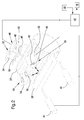
- a harvesting machine 10 shown in FIG. 1, in the manner of a self-propelled forage harvester builds on a frame 12, which is supported by front and rear wheels 14 and 16 becomes.
- the operation of the harvester 10 is carried out by a Driver's cab 18, from which a receiving device 20 for Recording of crop is visible.
- a receiving device 20 for Recording of crop is visible.
- the receiving device 20 picked up by a field crop, z. B.
- the Counter cutting edge 38 is provided with an adjusting device 40, for moving the counter-blade 38 in the horizontal direction on the cutter 22 to and from her set up is.
- the adjusting device 40 is used to set the Cutting gap.
- an im Near-infrared range operating optical (spectroscopic) Sensor 68 which contains a spectrometer. He takes care of that Discharge shaft 26 flowing through, chopped crop with broadband infrared light. The reflected by the crop Light is subjected to a wavelength analysis. Based on obtained spectra can be the ingredients of the crop be identified and quantified. In addition, the included Spectra information about the cutting length of the crop, because the cut surfaces have different spectra than those not give off cut surfaces.
- the sensor 68 can be constructed be, as described in EP 1 053 671 A, the disclosure thereof incorporated by reference into the present documents becomes.
- a monitoring device for monitoring the sharpness of the cutting blade 62 and the distance between the counter-blade 38 and the cutting blades 62 of the cutting device 22 is shown in more detail in FIG. It comprises a monitoring device 42, which with a first camera 44 is connected.
- the first camera 44 builds from an objective 46, an image sensor 48 (eg CCD) and a housing 50.
- Next to the camera 44 is a first one Lighting device 52 with a lamp 54 and a Collimator 56 arranged.
- a second camera 58 its construction coincides with the first camera 44 is also with the Monitoring device 42 connected.
- the second camera 58 is associated with a second illumination device 60 whose Construction with the first illumination device 52 matches.
- the first illumination device 52 is located in the upper Section of the cutting device 22 and illuminates it a large area.
- the first camera 44 detects the top of the Cutting device 22.
- the second illumination device 60 is located with respect to the direction of travel of the harvester 10 right above the counter-blade 38 and the counter-blade 38 adjacent region of the cutter 22 and illuminates the areas mentioned over a large area.
- the second Camera 50 is located with respect to the direction of the Harvesting machine 10 left above the counter-blade 38 and the the counter-blade 38 adjacent region of the Cutting device 22 and observed the said surfaces.
- the lenses 46 are formed on the image sensors 48 Illustrations of the cutting blades 62 (camera 44) and the Cutting gap and of the cutting gap adjacent area the cutting blade 62 and the counter-blade 38 (camera 50).
- the signals of the image sensors 48 become the monitoring device 42 supplied. They are digitized there and one Subjected to image processing, in the one based on the Signals from the camera 44, the cutting edges of the cutting blade 62nd extracted and compared with a nominal shape. results The result is that the cutting edges are not sufficiently sharp are a grinding device 76 is activated or the Driver given a corresponding note. Analog is the Grinding process dependent on the signals of the camera 44 completed.
- the gap between the counter-blade 38 and the cutting blades 62 from the signals of the camera 50th extracted and compared with a desired distance. Is he taller? or smaller than corresponding predefined limits, causes the monitoring device 42 an automatic Activation of the adjusting device 40 to the counter-blade 38 in a desired position to the cutting blades 62 spend, or give the driver a hint, accordingly proceed. Again, the movement of the Adjustment 40 stops when the Monitoring device 42 based on the signals of the camera 50th detects that the counter-blade 38 reaches its target position Has.
- the monitoring device 42 also receives signals from spectroscopic sensor 68. It performs a comparison between the cutting length measured by the spectroscopic sensor 68 was, and the nominal length of cut, by the Rotational speeds of the cutting device 22 and the pre-compression rollers 30 - 36 is calculable. If the cut length is greater than expected, Also, a grinding operation of the grinding device 76 caused, either automatically or by information of the Driver. Assign the signals from the spectroscopic sensor 68 an insufficient cut quality (too large, frayed Surface due to unclean cut), can analogously a Adjustment of the counter-blade 38 can be initiated.
- the detection the cutting edges of the cutting blade 62 problematic when the cutter 22 rotates.
- FIG. 3 A second embodiment of the invention is shown in FIG. 3 shown. Matching with the first embodiment Elements are provided with the same reference numerals.
- a laser 64 use with respect to the direction of the Harvesting machine 10 arranged right above the counter-blade 38 is, that is, where in Figure 2, the second Lighting device 64 is located.
- the laser 64 is through a Adjustment device 66 adjustable in two dimensions, i. he can be motorized around the vertical axis and around a horizontal, in Driving direction of the harvester 10 extending axis be pivoted.
- a camera 70 whose construction with the Cameras 44, 50 of FIG. 2 coincide with respect to FIG Direction of travel of the harvester 10 left above the Counter blade 38 arranged, ie where, in Figure 2 the second camera 50 is located.
- the adjusting 66 and the Camera 70 are connected to the monitoring device 42. Instead of the camera 70 could also be a non-imaging sensor in the form of a photodiode o. ⁇ . Find use.
- the monitoring device 42 causes the adjusting device 66, the gap between the counter-blade 38 and the Cutting knives 62 and the gap adjacent surfaces of the Counter-blade 38 and the cutting blade 62 in the direction of travel and the vertical, horizontal direction gradually scan. In this case, information is transmitted in the camera 70 generates the width of the gap. In addition, based on the of The cutting blades 62 reflected light about a conclusion their sharpness are drawn.
- Analogous to the first embodiment becomes an automatic activation of the grinding device 76 and / or the adjusting device 40 of the counter-blade 38th when, when analyzing the digitized Output signals of the camera 70 by means of the image processing software in the monitoring device 42 proves that the sharpness or gap width does not agree with setpoints, or it is a corresponding information to the driver issued.
- the termination of the grinding or adjustment process is also preferably due to appropriate signals the camera 70.
Abstract
Description
Die Erfindung betrifft eine Erntemaschine mit einer Aufnahmeeinrichtung zur Aufnahme von Erntegut, einer mit wenigstens einer Schneide versehenen Schneideinrichtung zum Schneiden oder Häckseln des Ernteguts, und mit einer Überwachungseinrichtung, die betreibbar ist, ein Signal zu erzeugen, das eine Information über die Schärfe der Schneide und/oder ihren Abstand zu einer Gegenschneide enthält, die mit einem Sollwert verglichen wird.The invention relates to a harvesting machine with a receiving device for receiving crops, one with at least a cutting provided cutting device for cutting or Chopping the crop, and with a monitoring device, which is operable to generate a signal containing information about the sharpness of the cutting edge and / or its distance to a cutting edge Contains counter blade, which is compared with a setpoint.
Erntemaschinen eingangs genannter Art, wie Feldhäcksler, Ballenpressen oder Ladewagen, sind mit Schneideinrichtungen zum Schneiden bzw. Häckseln des Ernteguts versehen. Derartige Schneideinrichtungen werden auch an Mähdreschern verwendet, um das ausgedroschene Stroh zu zerkleinern, wenn gewünscht. Für das Schneidergebnis ist es wichtig, dass die Schneide oder Schneiden der Schneideinrichtung eine hinreichende Schärfe aufweisen. Bei stumpfen Schneiden vergrößert sich auch der Energiebedarf für den Schneidvorgang. Falls das Erntegut nicht im freien Schnitt, d. h. ohne Verwendung einer Gegenschneide, zerteilt wird, findet eine Gegenschneide Verwendung. Der Abstand zwischen der Gegenschneide und der Schneide ist ebenfalls kritisch und möglichst genau einzustellen.Harvesters of the type mentioned, such as forage harvesters, balers or loading wagons, are equipped with cutting devices for Cutting or chopping the crop provided. such Cutting devices are also used on combine harvesters to shred the threshed straw if desired. For the Cutting result, it is important that the cutting edge or cutting the cutting device have a sufficient sharpness. at blunt cutting also increases the energy requirement for the cutting process. If the crop is not in free cut, d. H. without using a counter-blade, is divided a counterknife use. The distance between the Counter blade and the cutting edge is also critical and set as accurately as possible.
Bei den derzeit im Handel erhältlichen Erntemaschinen hängt es von der Entscheidung des Fahrers ab, ob und wann ein Schleifvorgang der Schneide erfolgt. Auch die Verstellung der Gegenschneide wird derzeit nur auf Veranlassung des Fahrers durchgeführt.It depends on the currently commercially available harvesters on the decision of the driver, if and when Grinding process of the cutting edge takes place. Also the adjustment of the Counter cutting is currently only at the instigation of the driver carried out.
In verschiedenen Veröffentlichungen wurden Einrichtungen zur
Feststellung der Schärfe von Häckselmessern beschrieben. Gemäß
der DE 40 23 113 A und der DE 40 23 114 A werden von den
Schneiden in induktiven Gebern induzierte Spannungen
ausgewertet. In der DE 199 03 153 A wird vorgeschlagen, die
Schnittkräfte zu erfassen. Die DE 102 35 919 A und DE 103 03 504
A offenbaren mechanische Erfassungen der Schwingungen der
Gegenschneide zur Schärfenbestimmung. Various publications have provided facilities for
Determination of the sharpness of chopping knives described. According to
Zur Messung des Abstands zwischen den Schneiden und der Gegenschneide wurden eine Reihe von Einrichtungen vorgeschlagen (DE 41 34 957 A, DE 43 35 786 A, EP 0 706 752 A), bei denen an der Gegenschneide ein Klopfsensor angebracht ist, dessen Ausgangssignal eine Funktion des Abstands zwischen der Gegenschneide und den Häckselmessern ist. Zur Messung des Abstands zwischen der Gegenschneide und den Häckselmessern sind weiterhin magnetische Sensoren bekannt, die einen mit der Gegenschneide verbundenen Permanentmagneten und eine Induktionsspule umfassen, in denen durch die vorbeistreichenden Häckselmesser eine EMK induziert wird, die verstärkt und detektiert wird (EP 0 943 888 A).To measure the distance between the cutting edges and the Counter-cutting have been proposed a number of facilities (DE 41 34 957 A, DE 43 35 786 A, EP 0 706 752 A), in which the counter cutting a knock sensor is mounted, whose Output signal a function of the distance between the Counter cutting and chopping knives is. To measure the Distance between the shearbar and the chopping knives Magnetic sensors are still known, the one with the Counter blade connected permanent magnets and a Induction coil include in which by the passing Chaff knife is induced an EMK, which amplifies and is detected (EP 0 943 888 A).
In der DE 38 16 206 A wird eine Schneideinrichtung für Doppelgewebe beschrieben, die ein Messer aufweist, dessen genaue Positionierung und Schärfe mittels eines optoelektronischen Sensors untersucht wird. Er setzt sich aus einer Kamera, die das Messer erfasst, und einer Auswerteelektronik zusammen. Dieser Druckschrift lässt sich keine Anregung entnehmen, den Sensor in einer landwirtschaftlichen Erntemaschine zu verwenden.In DE 38 16 206 A, a cutting device for Double tissue described which has a knife whose exact Positioning and sharpness by means of an optoelectronic Sensors is examined. He sits down from a camera that the Knife detected, and a transmitter together. This The document does not show any excitation, the sensor in to use an agricultural harvester.
Weiterhin liegen eine Reihe von Veröffentlichungen vor, in denen Erntegut optisch überwacht wird. Die US 6 119 442 A beschreibt einen Mähdrescher, bei dem eine Kamera auf das verarbeitete Erntegut gerichtet ist. Die Signale der Kamera werden ausgewertet und mit Sollwerten verglichen. Abhängig vom Ergebnis des Vergleichs werden Betriebsparameter des Mähdreschers verändert. In der EP 1 053 671 A wird vorgeschlagen, gehäckseltes Erntegut durch einen im nahen Infrarotbereich arbeitenden Sensor zu untersuchen, um Inhaltsstoffe zu erfassen. Aus den Messwerten des Sensors können auch Eigenschaften des Ernteguts abgeleitet werden, wie Rohfasergehalt oder Faserlänge. Diesen Schriften ist nicht entnehmbar, dass die Signale der optischen Sensoren zur Schärfenbestimmung oder Messung des Abstands zwischen Gegenschneide und Schneide geeignet sind.Furthermore, there are a number of publications in which Crop material is optically monitored. The US 6 119 442 A describes a harvester with a camera on it Crop is directed. The signals of the camera will be evaluated and compared with setpoints. Depending on the result of the comparison become operating parameters of the combine harvester changed. EP 1 053 671 A proposes chopped crop by one in the near infrared range working sensor to detect ingredients. From the measured values of the sensor can also properties of the Crop derived, such as crude fiber content or fiber length. These writings can not be deduced that the signals of the optical sensors for sharpening or measuring the Distance between counter blade and cutting edge are suitable.
Das der Erfindung zu Grunde liegende Problem wird darin gesehen, eine verbesserte Erntemaschine bereitzustellen, bei der die Entscheidung, ob ein Schärfen der Schneide oder eine Verstellung der Gegenschneide erforderlich ist, selbsttätig und exakt gefällt werden kann.The problem underlying the invention is seen therein to provide an improved harvesting machine in which the Deciding whether sharpening the cutting edge or an adjustment the counter blade is required, automatically and accurately can be made.
Dieses Problem wird erfindungsgemäß durch die Lehre des Patentanspruchs 1 gelöst, wobei in den weiteren Patentansprüchen Merkmale aufgeführt sind, die die Lösung in vorteilhafter Weise weiterentwickeln.This problem is inventively achieved by the teaching of the claim 1, wherein in the other claims features are listed, which the solution in an advantageous manner develop.
Es wird vorgeschlagen, eine Überwachungseinrichtung mit einem optisch arbeitenden Sensor zu verbinden, der betreibbar ist, die Schneideinrichtung optisch zu überwachen. Aus seinem Signal wird eine Information über die Schärfe der Schneide und/oder ihren Abstand zur Gegenschneide abgeleitet. Mit diesem System können auch defekte Messer und verschobene Messer detektiert werden. Alternativ oder zusätzlich wird das von der Schneideinrichtung geschnittene Erntegut, dessen Schnittlänge und -qualität von der Schärfe der Schneide und ggf. ihrem Abstand zur Gegenschneide abhängt, durch einen Sensor optisch überwacht, und das Signal des Sensors zur Gewinnung einer Information über die Schärfe der Schneide und/oder ihren Abstand zur Gegenschneide herangezogen. Die Überwachungseinrichtung stellt ein Ausgangssignal bereit, das eine Information über die Schärfe der Schneide und/oder den Abstand zur Gegenschneide enthält. Dieses Signal bzw. eine daraus abgeleitete Information wird durch den Fahrer oder selbsttätig mit einem Sollwert verglichen.It is proposed to have a monitoring device with a to connect optically working sensor, which is operable, the Visually monitor the cutting device. His signal becomes an information about the sharpness of the cutting edge and / or their Distance derived from the shearbar. With this system can also defective knives and shifted knives are detected. Alternatively or additionally, that of the cutting device sliced crop, the cut length and quality of which Sharpness of the cutting edge and possibly its distance to the counter-blade depends, optically monitored by a sensor, and the signal of the sensor for obtaining information about the sharpness of the Cutting edge and / or used their distance to the shearbar. The monitoring device provides an output signal this information about the sharpness of the cutting edge and / or the Distance to the counter blade contains. This signal or a Information derived from this is provided by the driver or automatically compared with a setpoint.
Ein Vorteil der Verwendung optischer Sensoren liegt in der erreichbaren Genauigkeit. Die Sensoren können, anders als die im Stand der Technik verwendeten induktiven bzw. mechanischen Sensoren, in einem gewissen Abstand von der Schneideinrichtung und somit in einer Position angebracht werden, in der sie den Einflüssen des Ernteguts und den von der Schneideinrichtung verursachten Vibrationen nur in einem relativ geringen Maß ausgesetzt werden. Außerdem kann ein Fehlen oder Defekt von Schneidmessern sofort erkannt und dem Fahrer mitgeteilt werden. An advantage of using optical sensors lies in the achievable accuracy. The sensors, unlike those in the The prior art used inductive or mechanical Sensors, at a certain distance from the cutting device and thus be placed in a position in which they Influences of the crop and of the cutting device caused vibrations only to a relatively small extent get abandoned. In addition, a lack or defect of Cutting knives are recognized immediately and communicated to the driver.
Abhängig von dem Ergebnis des Vergleichs kann dem Fahrer eine optische oder akustische Anzeige gegeben werden, die ihn veranlasst, einen Schleifvorgang durchzuführen bzw. den Abstand zwischen Schneideinrichtung und Gegenschneide neu einzustellen. Die genannten Vorgänge können auch ohne Einwirken des Fahrers selbsttätig und ggf. während der Fahrt oder des Erntevorgangs durchgeführt werden. Der Schleifvorgang kann ebenfalls durch den optischen Sensor erfasst werden, so dass bei einem anhand der Signale des Sensors im geeigneten Zeitpunkt beendeten Schleifvorgang nicht mehr Material abgeschliffen wird, als erforderlich. Analog wird der Verstellvorgang abhängig vom Signal des optischen Sensors beendet.Depending on the result of the comparison, the driver may have a be given visual or audible indication that him causes a grinding operation or the distance readjust between cutter and counterknife. The above operations can also without the intervention of the driver automatically and if necessary while driving or harvesting be performed. The grinding process can also by the optical sensor can be detected, so that at one of the basis of the Signals from the sensor ended at the appropriate time Grinding process is no longer sanding material than required. Analogously, the adjustment process depends on Signal of the optical sensor finished.
In einer Ausführungsform der Erfindung ist der sensitive Bereich eines Sensors der Überwachungseinrichtung auf die Schneideinrichtung gerichtet. Er erfasst somit die Form der Schneidkanten der Schneide und ist zur Erfassung ihrer Schärfe eingerichtet. Soll auch der Abstand zwischen Schneide und Gegenschneide erfasst werden, wird vorzugsweise zusätzlich die Gegenschneide optisch durch den Sensor erfasst.In one embodiment of the invention, the sensitive area a sensor of the monitoring device on the cutting device directed. He thus captures the shape of the Cutting edges of the cutting edge and is to capture their sharpness set up. Should also the distance between cutting edge and Counter-blade to be detected, is preferably additionally the Counter blade optically detected by the sensor.
Es sind verschiedene Möglichkeiten der Ausgestaltung des optischen Sensors denkbar. Zum Einen kann es sich um einen abbildenden Sensor handeln, d.h. um eine Kamera, die einen flächigen, ein- oder zweidimensional auflösenden Bildsensor aufweist. Dessen Signal wird vorzugsweise digitalisiert und mittels einer geeigneten Bildverarbeitungssoftware verarbeitet. Das Ergebnis dieser Verarbeitung ist eine Information über die Schärfe der Schneide bzw. ihren Abstand zur Gegenschneide. Um eine hinreichende Beleuchtung zu erzielen, kann eine Beaufschlagung des abzubildenden Bereichs mit Fremdlicht hilfreich sein. Die Lichtquelle kann punktförmig leuchten und die zu untersuchende Fläche abrastern oder sie kann großflächig leuchten. Zum Anderen kann es sich um einen nicht-abbildenden Sensor handeln, d. h. um ein lichtempfindliches Element, das ein von seiner Beleuchtungsstärke abhängiges Signal abgibt. There are different ways of designing the conceivable optical sensor. For one, it can be a imaging sensor, i. to a camera, the one flat, one or two-dimensional resolution image sensor having. Its signal is preferably digitized and processed by means of a suitable image processing software. The result of this processing is information about the Sharpness of the cutting edge or its distance to the counterknife. Around Adequate lighting can be achieved Loading the area to be imaged with extraneous light to be helpful. The light source can shine point-like and scan the area to be examined or it can be large area to shine. On the other hand it can be a non-depicting one Act sensor, d. H. to a photosensitive element, the emits a signal dependent on its illuminance.
Derartige Sensoren können insbesondere mit abtastenden Lichtquellen verwendet werden, z. B. Lasern. Die in diesem Absatz beschriebenen Sensoren können zur Erfassung der Schneideinrichtung und möglicherweise der Gegenschneide verwendet werden, aber für das von der Schneideinrichtung abgegebene Erntegut.Such sensors can in particular with scanning Light sources are used, for. B. lasers. The in this Paragraph described sensors can be used to capture the Cutting device and possibly the counter blade used but for the output from the cutter Crop.
Insbesondere zur Untersuchung des geschnittenen Ernteguts kann ein optischer Sensor (Spektrometer) Verwendung finden, der im Nahinfrarotbereich arbeitet. Die Schnittkanten des Ernteguts liefern andere Spektren als die nicht geschnittenen Flächen, da sie andere Oberflächenzusammensetzungen haben. Aus den gewonnenen Spektren lässt sich somit das Flächenverhältnis zwischen nicht-geschnittenen und geschnittenen Oberflächen und die Schnittlänge berechnen.In particular, for the investigation of the cut crop can an optical sensor (spectrometer) find use in the Near infrared area works. The cut edges of the crop provide spectra other than the uncut areas since they have other surface compositions. From the obtained spectra can thus be the area ratio between non-cut and cut surfaces and calculate the cutting length.
In der Zeichnung sind zwei nachfolgend näher beschriebene Ausführungsbeispiele der Erfindung dargestellt. Es zeigt:
- Fig. 1
- eine erfindungsgemäße Erntemaschine in Seitenansicht und in schematischer Darstellung,
- Fig. 2
- eine schematische Darstellung einer ersten Ausführungsform einer erfindungsgemäßen Überwachungseinrichtung, und
- Fig. 3
- eine schematische Darstellung einer zweiten Ausführungsform einer erfindungsgemäßen Überwachungseinrichtung.
- Fig. 1
- an inventive harvesting machine in side view and in a schematic representation,
- Fig. 2
- a schematic representation of a first embodiment of a monitoring device according to the invention, and
- Fig. 3
- a schematic representation of a second embodiment of a monitoring device according to the invention.
Eine in Figur 1 gezeigte Erntemaschine 10 in der Art eines
selbstfahrenden Feldhäckslers baut sich auf einem Rahmen 12 auf,
der von vorderen und rückwärtigen Rädern 14 und 16 getragen
wird. Die Bedienung der Erntemaschine 10 erfolgt von einer
Fahrerkabine 18 aus, von der aus eine Aufnahmeeinrichtung 20 zur
Aufnahme von Erntegut einsehbar ist. Mittels der Aufnahmeeinrichtung
20 von einem Feld aufgenommenes Erntegut, z. B. A harvesting
Mais, Gras oder dergleichen wird einer mit Schneidmessern 62
besetzten Schneideinrichtung 22 in der Art einer geschlossenen
Häckseltrommel zugeführt. Die vorlaufenden Schneiden der
Schneidmesser 62 häckseln das Erntegut in kleine Stücke und
geben es einer Fördervorrichtung 24 auf. Das Gut verlässt die
Erntemaschine 10 zu einem nebenher fahrenden Anhänger über einen
um die Hochachse drehbaren und in der Neigung verstellbaren
Austragsschacht 26. Zwischen der Schneideinrichtung 22 und der
Fördervorrichtung 24 erstreckt sich eine
Nachzerkleinerungsvorrichtung 28, durch die das zu fördernde
Erntegut der Fördervorrichtung 24 tangential zugeführt wird.Corn, grass or the like becomes one with cutting
Zwischen der Aufnahmevorrichtung 20 und der Schneideinrichtung
22 wird das Gut durch untere Vorpresswalzen 30, 32 und obere
Vorpresswalzen 34, 36 transportiert. Die über den Umfang der
Schneideinrichtung 22 verteilten Schneidmesser 62 wirken mit
einer Gegenschneide 38 zusammen, um das Gut zu häckseln. Die
Gegenschneide 38 ist mit einer Verstelleinrichtung 40 versehen,
die zum Verfahren der Gegenschneide 38 in horizontaler Richtung
auf die Schneideinrichtung 22 zu und von ihr fort eingerichtet
ist. Die Verstelleinrichtung 40 dient zum Einstellen des
Schneidspalts.Between the receiving
An der Oberseite des Austragschachts 26 befindet sich ein im
Nahinfrarotbereich arbeitender optischer (spektroskopischer)
Sensor 68, der ein Spektrometer enthält. Er beaufschlagt das den
Austragschacht 26 durchströmende, gehäckselte Erntegut mit
breitbandigem Infrarotlicht. Das durch das Erntegut reflektierte
Licht wird einer Wellenlängenanalyse unterzogen. Anhand der
gewonnenen Spektren können die Inhaltsstoffe des Ernteguts
identifiziert und quantifiziert werden. Außerdem enthalten die
Spektren eine Information über die Schnittlänge des Ernteguts,
da die geschnittenen Oberflächen andere Spektren als die nicht
geschnittenen Oberflächen abgeben. Der Sensor 68 kann aufgebaut
sein, wie in der EP 1 053 671 A beschrieben, deren Offenbarung
durch Verweis mit in die vorliegenden Unterlagen aufgenommen
wird. At the top of the
Eine erfindungsgemäße Überwachungseinrichtung zur Überwachung
der Schärfe der Schneidmesser 62 sowie des Abstands zwischen
der Gegenschneide 38 und den Schneidmessern 62 der Schneideinrichtung
22 ist in der Figur 2 detaillierter dargestellt.
Sie umfasst eine Überwachungseinrichtung 42, die mit einer
ersten Kamera 44 verbunden ist. Die erste Kamera 44 baut sich
aus einem Objektiv 46, einem Bildsensor 48 (z. B. CCD) und
einem Gehäuse 50 auf. Neben der Kamera 44 ist eine erste
Beleuchtungseinrichtung 52 mit einer Lampe 54 und einem
Kollimator 56 angeordnet. Eine zweite Kamera 58, deren Aufbau
mit der ersten Kamera 44 übereinstimmt, ist ebenfalls mit der
Überwachungseinrichtung 42 verbunden. Der zweiten Kamera 58
ist eine zweite Beleuchtungseinrichtung 60 zugeordnet, deren
Aufbau mit der ersten Beleuchtungseinrichtung 52
übereinstimmt.A monitoring device according to the invention for monitoring
the sharpness of the
Die erste Beleuchtungseinrichtung 52 befindet sich im oberen
Bereich der Schneideinrichtung 22 und beleuchtet ihn
großflächig. Die erste Kamera 44 erfasst die Oberseite der
Schneideinrichtung 22. Die zweite Beleuchtungseinrichtung 60
befindet sich bezüglich der Fahrtrichtung der Erntemaschine 10
rechts oberhalb der Gegenschneide 38 und des der Gegenschneide
38 benachbarten Bereichs der Schneideinrichtung 22 und
beleuchtet die genannten Flächen großflächig. Die zweite
Kamera 50 befindet sich bezüglich der Fahrtrichtung der
Erntemaschine 10 links oberhalb der Gegenschneide 38 und des
der Gegenschneide 38 benachbarten Bereichs der
Schneideinrichtung 22 und beobachtet die genannten Flächen.The
Durch die Objektive 46 entstehen auf den Bildsensoren 48
Abbildungen der Schneidmesser 62 (Kamera 44) und des
Schneidspalts sowie des dem Schneidspalt benachbarten Bereichs
der Schneidmesser 62 und der Gegenschneide 38 (Kamera 50).The
Die Signale der Bildsensoren 48 werden der Überwachungseinrichtung
42 zugeführt. Sie werden dort digitalisiert und einer
Bildverarbeitung unterzogen, in der zum Einen anhand der
Signale der Kamera 44 die Schneidkanten der Schneidmesser 62
extrahiert und mit einer Sollform verglichen werden. Ergibt
sich dabei, dass die Schneidkanten nicht hinreichend scharf
sind, wird eine Schleifeinrichtung 76 aktiviert oder dem
Fahrer ein entsprechender Hinweis gegeben. Analog wird der
Schleifvorgang abhängig von den Signalen der Kamera 44
beendet.The signals of the
Zum Anderen wird der Spalt zwischen der Gegenschneide 38 und
den Schneidmessern 62 aus den Signalen der Kamera 50
extrahiert und mit einem Sollabstand verglichen. Ist er größer
oder kleiner als entsprechende, vordefinierte Grenzwerte,
veranlasst die Überwachungseinrichtung 42 eine selbsttätige
Aktivierung der Verstelleinrichtung 40, um die Gegenschneide
38 in eine Sollposition zu den Schneidmessern 62 zu
verbringen, oder gibt dem Fahrer einen Hinweis, entsprechend
vorzugehen. Auch hier wird die Bewegung der
Verstelleinrichtung 40 beendet, wenn die
Überwachungseinrichtung 42 anhand der Signale der Kamera 50
erkennt, dass die Gegenschneide 38 ihre Sollposition erreicht
hat.On the other hand, the gap between the counter-blade 38 and
the
Die Überwachungseinrichtung 42 erhält auch Signale vom
spektroskopischen Sensor 68. Sie führt einen Vergleich zwischen
der Schnittlänge, die vom spektroskopischen Sensor 68 gemessen
wurde, und der nominellen Schnittlänge durch, die anhand der
Drehzahlen der Schneideinrichtung 22 und der Vorpresswalzen 30 -
36 errechenbar ist. Ist die Schnittlänge größer als erwartet,
wird ebenfalls ein Schleifvorgang der Schleifeinrichtung 76
veranlasst, entweder selbsttätig oder durch eine Information des
Fahrers. Weisen die Signale des spektroskopischen Sensors 68 auf
eine unzureichende Schnittqualität hin (zu große, ausgefaserte
Oberfläche aufgrund unsauberen Schnitts), kann analog eine
Verstellung der Gegenschneide 38 veranlasst werden.The
Es wäre auch denkbar, auf die zweite Kamera 50 und die zweite
Beleuchtungseinrichtung 60 zu verzichten, falls nur die Schärfe
der Schneidmesser 62 erfasst werden soll. Man könnte auch die
zweite Kamera 50 zur Bestimmung der Schärfe der Schneidmesser 62
verwenden und auf die erste Kamera 44 und die erste
Beleuchtungseinrichtung 52 verzichten. Man könnte auch nur den
spektroskopischen Sensor 68 verwenden oder auf ihn verzichten.It would also be conceivable on the
Bei dem beschriebenen Messvorgang ist insbesondere die Erfassung
der Schnittkanten der Schneidmesser 62 problematisch, wenn sich
die Schneideinrichtung 22 dreht. Man verwendet eine Kamera 44
mit entsprechender Geschwindigkeit und Auflösung oder versieht
sie mit einem Hochgeschwindigkeitsverschluss, bzw. man nutzt
eine gepulste Beleuchtungseinrichtung 52, die Blitze hinreichender
Kürze abgibt. Alternativ oder zusätzlich wird die Kamera 44
nur genutzt, wenn sich die Schneideinrichtung 22 relativ langsam
dreht oder steht. Da man mit der Kamera 50 nur den Spalt
zwischen Gegenschneide 38 und den Schneidmessern 62 erfassen
will, so dass eine aufgrund der sich drehenden
Schneideinrichtung 22 unscharfe Abbildung der Schneidmesser 62
ohne Belang ist, während die von ihnen beschriebene Hüllkurve
interessant ist, ist die Messung hier weniger kritisch.In the case of the described measuring process, in particular the detection
the cutting edges of the
Eine zweite Ausführungsform der Erfindung ist in Figur 3
dargestellt. Mit der ersten Ausführungsform übereinstimmende
Elemente sind mit denselben Bezugszeichen versehen. Hier findet
ein Laser 64 Verwendung, der bezüglich der Fahrtrichtung der
Erntemaschine 10 rechts oberhalb der Gegenschneide 38 angeordnet
ist, also dort, wo sich in Figur 2 die zweite
Beleuchtungseinrichtung 64 befindet. Der Laser 64 ist durch eine
Verstelleinrichtung 66 in zwei Dimensionen verstellbar, d.h. er
kann motorisch um die Hochachse und um eine horizontale, sich in
Fahrtrichtung der Erntemaschine 10 erstreckende Achse
verschwenkt werden. Eine Kamera 70, deren Aufbau mit dem der
Kameras 44, 50 aus Figur 2 übereinstimmt, ist bezüglich der
Fahrtrichtung der Erntemaschine 10 links oberhalb der
Gegenschneide 38 angeordnet, also dort, wo sich in Figur 2 die
zweite Kamera 50 befindet. Die Verstelleinrichtung 66 und die
Kamera 70 sind mit der Überwachungseinrichtung 42 verbunden.
Anstelle der Kamera 70 könnte auch ein nicht abbildender Sensor
in Form einer Fotodiode o. ä. Verwendung finden.A second embodiment of the invention is shown in FIG. 3
shown. Matching with the first embodiment
Elements are provided with the same reference numerals. Here you will find
a
Die Überwachungseinrichtung 42 veranlasst die Verstelleinrichtung
66, den Spalt zwischen der Gegenschneide 38 und den
Schneidmessern 62 und die dem Spalt benachbarten Flächen der
Gegenschneide 38 und der Schneidmesser 62 in der Fahrtrichtung
und der dazu senkrechten, horizontalen Richtung nach und nach
abzutasten. Dabei wird in der Kamera 70 eine Information über
die Breite des Spalts generiert. Außerdem kann anhand des von
den Schneidmessern 62 reflektierten Lichts ein Rückschluss über
deren Schärfe gezogen werden. Analog zu der ersten Ausführungsform
wird eine selbsttätige Aktivierung der Schleifeinrichtung
76 und/oder der Verstelleinrichtung 40 der Gegenschneide 38
veranlasst, wenn sich bei der Analyse der digitalisierten
Ausgangssignale der Kamera 70 mittels der Bildverarbeitungssoftware
in der Überwachungseinrichtung 42 herausstellt, dass
die Schärfe bzw. Spaltbreite nicht mit Sollwerten übereinstimmt,
bzw. es wird eine entsprechende Information an den Fahrer
abgegeben. Die Beendigung des Schleif- bzw. Verstellvorgangs
erfolgt ebenfalls vorzugsweise aufgrund entsprechender Signale
der Kamera 70.The
Claims (10)
Applications Claiming Priority (2)
| Application Number | Priority Date | Filing Date | Title |
|---|---|---|---|
| DE10346412A DE10346412A1 (en) | 2003-10-07 | 2003-10-07 | Harvesting machine with a monitoring device for monitoring the sharpness of cutting blades and / or their distance from a counter-blade |
| DE10346412 | 2003-10-07 |
Publications (3)
| Publication Number | Publication Date |
|---|---|
| EP1522214A2 true EP1522214A2 (en) | 2005-04-13 |
| EP1522214A3 EP1522214A3 (en) | 2006-03-15 |
| EP1522214B1 EP1522214B1 (en) | 2008-02-27 |
Family
ID=34306290
Family Applications (1)
| Application Number | Title | Priority Date | Filing Date |
|---|---|---|---|
| EP04104762A Not-in-force EP1522214B1 (en) | 2003-10-07 | 2004-09-29 | Harvester with a controle device for controlling the sharpness of cutting knifes and/or their clearance to the counterknife |
Country Status (5)
| Country | Link |
|---|---|
| US (1) | US6931828B2 (en) |
| EP (1) | EP1522214B1 (en) |
| AT (1) | ATE387083T1 (en) |
| CA (1) | CA2479803C (en) |
| DE (2) | DE10346412A1 (en) |
Cited By (11)
| Publication number | Priority date | Publication date | Assignee | Title |
|---|---|---|---|---|
| EP1862061A1 (en) * | 2006-05-29 | 2007-12-05 | CLAAS Selbstfahrende Erntemaschinen GmbH | Agricultural harvester |
| EP1956361A2 (en) | 2007-02-07 | 2008-08-13 | Deere & Company | Measuring device for optical and spectroscopic analysis of a sample |
| EP2008508A1 (en) | 2007-06-27 | 2008-12-31 | CLAAS Selbstfahrende Erntemaschinen GmbH | Harvesting machine with monitoring of cut parts |
| EP2225931A1 (en) | 2009-03-02 | 2010-09-08 | CLAAS Selbstfahrende Erntemaschinen GmbH | Agricultural harvester |
| EP2311601A1 (en) * | 2009-10-13 | 2011-04-20 | CLAAS Saulgau GmbH | Method and device for detecting the sharpness of cutter blades on a chaff cutter |
| EP2805603A1 (en) | 2013-05-22 | 2014-11-26 | CLAAS Agrosystems KGaA | Device and method for monitoring cutting sharpness |
| EP3366106B1 (en) | 2017-02-27 | 2020-04-08 | CLAAS Selbstfahrende Erntemaschinen GmbH | Agricultural harvesting system |
| EP3738427A1 (en) | 2019-05-16 | 2020-11-18 | CLAAS Selbstfahrende Erntemaschinen GmbH | Cutting sharpening detection device |
| EP4218394A1 (en) * | 2022-01-27 | 2023-08-02 | CLAAS Selbstfahrende Erntemaschinen GmbH | Self-propelled forage harvester and method for operating a self-propelled forage harvester |
| DE102022107805A1 (en) | 2022-04-01 | 2023-10-05 | Deere & Company | Machine for forage harvesting with predictive control |
| EP4342280A1 (en) * | 2022-09-26 | 2024-03-27 | Deere & Company | Rotary cutter-bar with blade sensor |
Families Citing this family (42)
| Publication number | Priority date | Publication date | Assignee | Title |
|---|---|---|---|---|
| DE10346116A1 (en) * | 2003-10-04 | 2005-04-21 | Deere & Co | Chopping device for a forage harvester |
| DE602004011373T2 (en) * | 2004-12-18 | 2008-07-03 | Deere & Company, Moline | harvester |
| US8393137B1 (en) * | 2006-07-05 | 2013-03-12 | Lon Owen Crosby | Biomass harvesting system |
| US7877970B1 (en) * | 2006-07-05 | 2011-02-01 | Lon Owen Crosby | Biomass harvesting system |
| US7953560B2 (en) * | 2006-12-28 | 2011-05-31 | Lexmark International, Inc. | Method for measuring doctor blade geometric deviations |
| US7826048B2 (en) * | 2006-12-28 | 2010-11-02 | Lexmark International, Inc. | Apparatus for measuring doctor blade geometric deviations |
| DE102009029675B4 (en) * | 2008-11-25 | 2023-03-16 | Deere & Company | Device and method for detecting the sharpness of chopper knives |
| DE102009047584B4 (en) | 2009-12-07 | 2019-06-19 | Deere & Company | Chopping knife for a forage harvester and arrangement for detecting its sharpness |
| US8587660B2 (en) * | 2010-07-30 | 2013-11-19 | General Electric Company | Image recording assemblies and coupling mechanisms for stator vane inspection |
| DE102010037358A1 (en) * | 2010-09-07 | 2012-03-08 | Claas Selbstfahrende Erntemaschinen Gmbh | cutter |
| DE102010051068A1 (en) * | 2010-11-12 | 2012-05-16 | Claas Selbstfahrende Erntemaschinen Gmbh | Agricultural harvester |
| US9631964B2 (en) | 2011-03-11 | 2017-04-25 | Intelligent Agricultural Solutions, Llc | Acoustic material flow sensor |
| US10318138B2 (en) | 2011-03-11 | 2019-06-11 | Intelligent Agricultural Solutions Llc | Harvesting machine capable of automatic adjustment |
| US10321624B2 (en) | 2011-03-11 | 2019-06-18 | Intelligent Agriculture Solutions LLC | Air seeder manifold system |
| US9629308B2 (en) | 2011-03-11 | 2017-04-25 | Intelligent Agricultural Solutions, Llc | Harvesting machine capable of automatic adjustment |
| DE102011055851A1 (en) * | 2011-05-21 | 2012-11-22 | Claas Saulgau Gmbh | Method for detecting the sharpness of cutting edges of chopping knives |
| DE102011052726A1 (en) * | 2011-08-16 | 2013-02-21 | Claas Selbstfahrende Erntemaschinen Gmbh | Method and device for detecting the state of a cutting device |
| DE102011082908A1 (en) * | 2011-09-19 | 2013-03-21 | Deere & Company | Method and arrangement for optically evaluating crops in a harvester |
| US9119388B2 (en) * | 2013-03-15 | 2015-09-01 | Harvest Moon Automation Inc. | Selectively eradicating plants |
| DE102014218408A1 (en) * | 2013-10-31 | 2015-04-30 | Deere & Company | Arrangement for detecting the sharpness of chopping knives |
| BE1022071B1 (en) * | 2014-03-12 | 2016-02-15 | Cnh Industrial Belgium Nv | SYSTEM AND METHOD FOR DETERMINING KNIFE WEAR |
| WO2015136026A1 (en) * | 2014-03-12 | 2015-09-17 | Cnh Industrial Belgium Nv | System and method for determining knife usage |
| US8915766B1 (en) | 2014-05-22 | 2014-12-23 | Dmitriy Kolchin | Automatic knife sharpener and a method for its use |
| US10085379B2 (en) | 2014-09-12 | 2018-10-02 | Appareo Systems, Llc | Grain quality sensor |
| CA2961204C (en) | 2014-09-12 | 2023-01-03 | Appareo Systems, Llc | Non-image-based grain quality sensor |
| DE102016207565A1 (en) | 2016-05-03 | 2017-11-09 | Deere & Company | Device for detecting the sharpness of blades of a harvester for harvesting of a crop in the shape of a chunk |
| CN107771521A (en) * | 2016-08-30 | 2018-03-09 | 勇猛机械股份有限公司 | It is a kind of to shred stationary knife and the adjusting means in moving knife gap |
| US10820492B2 (en) | 2016-12-12 | 2020-11-03 | Kubota Corporation | Work vehicle |
| BE1024884B1 (en) | 2017-01-06 | 2018-08-09 | Cnh Industrial Belgium Nv | FIELD CHOPPER WITH MECHANISM FOR MONITORING SCISSORS SHEET AND CUT DRUM |
| CN108040628B (en) * | 2017-12-26 | 2020-06-05 | 安徽鼎梁科技能源股份有限公司 | Special starch cutting machine of on-vehicle straw |
| CN109037826B (en) * | 2018-09-03 | 2023-07-25 | 刘强 | Device for automatically cutting upper cover and bottom cover of storage battery |
| DE102018216320A1 (en) | 2018-09-25 | 2020-03-26 | Deere & Company | Arrangement for adjusting the position of the shearbar of a forage harvester |
| DE102019105982A1 (en) * | 2019-03-08 | 2020-09-10 | Claas Selbstfahrende Erntemaschinen Gmbh | Agricultural harvesting machine and method for operating an agricultural harvesting machine |
| CN109990184B (en) * | 2019-04-22 | 2020-06-02 | 中国水利水电科学研究院 | Farmland crop information acquisition device |
| US11324164B2 (en) * | 2019-08-12 | 2022-05-10 | Cnh Industrial America Llc | System and device for monitoring a condition of a sickle section of an agricultural machine |
| US20210195833A1 (en) * | 2019-12-30 | 2021-07-01 | Agco Corporation | System and method using nir sensing to control height of cutting element on agricultural machine |
| DE102020102596A1 (en) * | 2020-02-03 | 2021-08-05 | Claas Selbstfahrende Erntemaschinen Gmbh | Cutting table length adaptation |
| DE102020000725B4 (en) | 2020-02-04 | 2021-10-28 | Maschinenfabrik Bernard Krone GmbH & Co. KG | Agricultural working machine with a measuring arrangement, measuring arrangement for the agricultural working machine and method for measuring a contour of a moving component of the agricultural working machine |
| GB202007966D0 (en) * | 2020-05-28 | 2020-07-15 | Agco Int Gmbh | Forage harvester adjustment apparatus |
| GB202007962D0 (en) * | 2020-05-28 | 2020-07-15 | Agco Int Gmbh | Forage harvester adjustment apparatus |
| US20220022375A1 (en) * | 2020-07-21 | 2022-01-27 | Deere & Company | Harvester implement degree of crop processing sensor system |
| DE102022101658A1 (en) * | 2022-01-25 | 2023-07-27 | Deere & Company | grinding device |
Citations (8)
| Publication number | Priority date | Publication date | Assignee | Title |
|---|---|---|---|---|
| DE4023113A1 (en) | 1989-08-11 | 1991-06-13 | Agritechnik Ing Betrieb | METHOD FOR DETERMINING THE SHARPNESS OF CHOPPING KNIVES |
| DE4023114A1 (en) | 1989-08-11 | 1991-08-01 | Agritechnik Ing Betrieb | METHOD FOR DETERMINING THE SHARPNESS OF CHOPPING KNIVES |
| DE4134957A1 (en) | 1991-10-23 | 1993-04-29 | Claas Ohg | Counter cutter setting device for straw chopping machine - uses sensor signals indicating impact between counter cutter rail and rotating cutting blades |
| DE4335786A1 (en) | 1993-10-20 | 1995-04-27 | Claas Bhohg | Safety device of a shearbar adjuster |
| EP0706752A1 (en) | 1987-05-05 | 1996-04-17 | New Holland Belgium N.V. | Shear bar adjustment apparatus including vibration sensor means with adjustable threshold |
| DE19903153C1 (en) | 1999-01-27 | 2000-03-16 | Case Harvesting Sys Gmbh | Method of determining the sharpness of agricultural chopping blades involves comparing reference load quotient on counter blade with varying quotient measured during operation |
| DE10235919A1 (en) | 2002-07-30 | 2004-02-26 | Deere & Company, Moline | Method and arrangement for determining the sharpness of chopping knives |
| DE10303504A1 (en) | 2003-01-30 | 2004-09-02 | Deere & Company, Moline | Device for measuring and / or checking the distance between a shear bar and a chopping knife |
Family Cites Families (12)
| Publication number | Priority date | Publication date | Assignee | Title |
|---|---|---|---|---|
| US4479346A (en) * | 1981-03-31 | 1984-10-30 | Noel Chandler | Automatic electrical bed knife adjuster |
| US4678130A (en) * | 1985-10-04 | 1987-07-07 | New Holland Inc. | Quick adjust shearbar mechanism |
| US4934612A (en) * | 1988-03-28 | 1990-06-19 | Deere & Company | Automatic forage harvester shearbar adjusting |
| DE3816206A1 (en) | 1988-05-11 | 1989-11-16 | Wiele Michel Van De Nv | Double-fabric cutting appliance |
| DE3919055A1 (en) * | 1989-06-10 | 1990-12-13 | Claas Saulgau Gmbh | STORAGE AND ADJUSTING DEVICE FOR THE COUNTERBOW RAIL FROM FIELD CHOPPER |
| US5098027A (en) * | 1990-02-28 | 1992-03-24 | Ford New Holland, Inc. | Automatic knife sharpening system for forage harvesters |
| GB2299256A (en) * | 1995-03-31 | 1996-10-02 | Ford New Holland Nv | Forage harvester cutting apparatus |
| DE19812271B4 (en) | 1998-03-20 | 2013-08-01 | Deere & Company | Device for monitoring the distance between a knife of a rotating cutting drum and a counter-cutting edge of a harvester |
| US6119442A (en) * | 1999-05-14 | 2000-09-19 | Case Corporation | Combine setting autoadjust with machine vision |
| DE19922867C5 (en) | 1999-05-19 | 2015-04-23 | Deere & Company | Harvesting machine with a measuring device for measuring ingredients in and / or properties of crops |
| DE10017985A1 (en) * | 2000-04-11 | 2001-10-18 | Deere & Co | Grinding device |
| DE10220699A1 (en) * | 2002-05-10 | 2003-12-24 | Deere & Co | Device for adjusting the cutting length of a chopping device |
-
2003
- 2003-10-07 DE DE10346412A patent/DE10346412A1/en not_active Withdrawn
-
2004
- 2004-08-11 US US10/915,854 patent/US6931828B2/en active Active
- 2004-08-31 CA CA002479803A patent/CA2479803C/en not_active Expired - Fee Related
- 2004-09-29 DE DE502004006304T patent/DE502004006304D1/en active Active
- 2004-09-29 EP EP04104762A patent/EP1522214B1/en not_active Not-in-force
- 2004-09-29 AT AT04104762T patent/ATE387083T1/en not_active IP Right Cessation
Patent Citations (8)
| Publication number | Priority date | Publication date | Assignee | Title |
|---|---|---|---|---|
| EP0706752A1 (en) | 1987-05-05 | 1996-04-17 | New Holland Belgium N.V. | Shear bar adjustment apparatus including vibration sensor means with adjustable threshold |
| DE4023113A1 (en) | 1989-08-11 | 1991-06-13 | Agritechnik Ing Betrieb | METHOD FOR DETERMINING THE SHARPNESS OF CHOPPING KNIVES |
| DE4023114A1 (en) | 1989-08-11 | 1991-08-01 | Agritechnik Ing Betrieb | METHOD FOR DETERMINING THE SHARPNESS OF CHOPPING KNIVES |
| DE4134957A1 (en) | 1991-10-23 | 1993-04-29 | Claas Ohg | Counter cutter setting device for straw chopping machine - uses sensor signals indicating impact between counter cutter rail and rotating cutting blades |
| DE4335786A1 (en) | 1993-10-20 | 1995-04-27 | Claas Bhohg | Safety device of a shearbar adjuster |
| DE19903153C1 (en) | 1999-01-27 | 2000-03-16 | Case Harvesting Sys Gmbh | Method of determining the sharpness of agricultural chopping blades involves comparing reference load quotient on counter blade with varying quotient measured during operation |
| DE10235919A1 (en) | 2002-07-30 | 2004-02-26 | Deere & Company, Moline | Method and arrangement for determining the sharpness of chopping knives |
| DE10303504A1 (en) | 2003-01-30 | 2004-09-02 | Deere & Company, Moline | Device for measuring and / or checking the distance between a shear bar and a chopping knife |
Cited By (19)
| Publication number | Priority date | Publication date | Assignee | Title |
|---|---|---|---|---|
| EP1862061A1 (en) * | 2006-05-29 | 2007-12-05 | CLAAS Selbstfahrende Erntemaschinen GmbH | Agricultural harvester |
| EP1956361A2 (en) | 2007-02-07 | 2008-08-13 | Deere & Company | Measuring device for optical and spectroscopic analysis of a sample |
| EP1956361A3 (en) * | 2007-02-07 | 2009-11-04 | Deere & Company | Measuring device for optical and spectroscopic analysis of a sample |
| US7804588B2 (en) | 2007-02-07 | 2010-09-28 | Deere & Company | Measuring device for optical and spectroscopic examination of a sample |
| EP2008508A1 (en) | 2007-06-27 | 2008-12-31 | CLAAS Selbstfahrende Erntemaschinen GmbH | Harvesting machine with monitoring of cut parts |
| DE102007030167A1 (en) | 2007-06-27 | 2009-01-08 | Claas Selbstfahrende Erntemaschinen Gmbh | Harvester with quality control of the cutting edges |
| EP2225931A1 (en) | 2009-03-02 | 2010-09-08 | CLAAS Selbstfahrende Erntemaschinen GmbH | Agricultural harvester |
| DE102009011035A1 (en) | 2009-03-02 | 2010-09-09 | Claas Selbstfahrende Erntemaschinen Gmbh | Agricultural harvester |
| EP2311601A1 (en) * | 2009-10-13 | 2011-04-20 | CLAAS Saulgau GmbH | Method and device for detecting the sharpness of cutter blades on a chaff cutter |
| EP2805603A1 (en) | 2013-05-22 | 2014-11-26 | CLAAS Agrosystems KGaA | Device and method for monitoring cutting sharpness |
| EP3366106B1 (en) | 2017-02-27 | 2020-04-08 | CLAAS Selbstfahrende Erntemaschinen GmbH | Agricultural harvesting system |
| EP3366106B2 (en) † | 2017-02-27 | 2023-01-04 | CLAAS Selbstfahrende Erntemaschinen GmbH | Agricultural harvesting system |
| EP3738427A1 (en) | 2019-05-16 | 2020-11-18 | CLAAS Selbstfahrende Erntemaschinen GmbH | Cutting sharpening detection device |
| EP3738429A1 (en) | 2019-05-16 | 2020-11-18 | CLAAS Selbstfahrende Erntemaschinen GmbH | Driver assistance system of a forage harvester |
| EP3738428A1 (en) | 2019-05-16 | 2020-11-18 | CLAAS Selbstfahrende Erntemaschinen GmbH | Driver assistance system of a forage harvester |
| US11566883B2 (en) | 2019-05-16 | 2023-01-31 | Claas Selbstfahrende Erntemaschinen Gmbh | Cutting sharpness detection device |
| EP4218394A1 (en) * | 2022-01-27 | 2023-08-02 | CLAAS Selbstfahrende Erntemaschinen GmbH | Self-propelled forage harvester and method for operating a self-propelled forage harvester |
| DE102022107805A1 (en) | 2022-04-01 | 2023-10-05 | Deere & Company | Machine for forage harvesting with predictive control |
| EP4342280A1 (en) * | 2022-09-26 | 2024-03-27 | Deere & Company | Rotary cutter-bar with blade sensor |
Also Published As
| Publication number | Publication date |
|---|---|
| CA2479803A1 (en) | 2005-04-07 |
| US6931828B2 (en) | 2005-08-23 |
| ATE387083T1 (en) | 2008-03-15 |
| DE10346412A1 (en) | 2005-05-25 |
| CA2479803C (en) | 2007-06-26 |
| EP1522214A3 (en) | 2006-03-15 |
| DE502004006304D1 (en) | 2008-04-10 |
| EP1522214B1 (en) | 2008-02-27 |
| US20050072135A1 (en) | 2005-04-07 |
Similar Documents
| Publication | Publication Date | Title |
|---|---|---|
| EP1522214B1 (en) | Harvester with a controle device for controlling the sharpness of cutting knifes and/or their clearance to the counterknife | |
| EP2452550B1 (en) | Agricultural harvester | |
| EP2401906B1 (en) | Device for detecting and determining the composition of bulk material | |
| EP2119339B1 (en) | Measuring assembly for calculating the content materials of a sample removed from a stalk crop flow | |
| DE102008043716B4 (en) | Device and method for recording the stock density of plants in a field | |
| EP2436258B1 (en) | Agricultural selfpropelled chopper having device for determining the sharpness of cutting blades | |
| EP2008508B1 (en) | Harvesting machine with monitoring of cut parts | |
| DE102010002343A1 (en) | Forage harvester with a chopper and a post-processing device arranged downstream of the chopper | |
| BE1022370B1 (en) | ARRANGEMENT FOR DETECTING THE SHARP OF HACKSELMESSERN | |
| DE102011085380A1 (en) | Arrangement and method for the prospective investigation of plants to be picked up with a harvester | |
| EP1442652B1 (en) | Device for measuring and/or controlling the clearance between a counter knife and a cutting chopper | |
| DE102008043377A1 (en) | Measuring arrangement for the spectroscopic examination and throughput detection of a crop stream | |
| DE102012207591B3 (en) | Arrangement for cutting length control for field chopper, has control device that is operable to receive output signal based on desired cutting length, sensor signal and stored correlation, where cutting length is set at given sensor signal | |
| EP1582260A1 (en) | Device for setting the position of a shear bar in respect of a shredder | |
| DE102009047584B4 (en) | Chopping knife for a forage harvester and arrangement for detecting its sharpness | |
| DE102017201423A1 (en) | Arrangement for detecting the degree of wear of chopping blades of a chopper drum of a forage harvester | |
| EP1905292B1 (en) | Measuring device for measuring parameters | |
| EP1754407B1 (en) | Agricultural harvesting machine | |
| EP3498080A1 (en) | Forage harvester | |
| DE102012205337A1 (en) | Self-propelled forage harvester for harvesting crop plants used as e.g. animal feed, has control unit that passes counter blades to second position far from first position relative to cutting drum, if crop situation does not exists | |
| EP2805603B1 (en) | Device and method for monitoring cutting sharpness | |
| DE19716183A1 (en) | Method and device for measuring distance in agricultural machinery | |
| DE102018004219A1 (en) | Agricultural harvester | |
| DE102020129795A1 (en) | Forage harvester with conditioning rollers and wear sensor |
Legal Events
| Date | Code | Title | Description |
|---|---|---|---|
| PUAI | Public reference made under article 153(3) epc to a published international application that has entered the european phase |
Free format text: ORIGINAL CODE: 0009012 |
|
| AK | Designated contracting states |
Kind code of ref document: A2 Designated state(s): AT BE BG CH CY CZ DE DK EE ES FI FR GB GR HU IE IT LI LU MC NL PL PT RO SE SI SK TR |
|
| AX | Request for extension of the european patent |
Extension state: AL HR LT LV MK |
|
| PUAL | Search report despatched |
Free format text: ORIGINAL CODE: 0009013 |
|
| AK | Designated contracting states |
Kind code of ref document: A3 Designated state(s): AT BE BG CH CY CZ DE DK EE ES FI FR GB GR HU IE IT LI LU MC NL PL PT RO SE SI SK TR |
|
| AX | Request for extension of the european patent |
Extension state: AL HR LT LV MK |
|
| 17P | Request for examination filed |
Effective date: 20060915 |
|
| AKX | Designation fees paid |
Designated state(s): AT BE BG CH CY CZ DE DK EE ES FI FR GB GR HU IE IT LI LU MC NL PL PT RO SE SI SK TR |
|
| GRAP | Despatch of communication of intention to grant a patent |
Free format text: ORIGINAL CODE: EPIDOSNIGR1 |
|
| GRAS | Grant fee paid |
Free format text: ORIGINAL CODE: EPIDOSNIGR3 |
|
| GRAA | (expected) grant |
Free format text: ORIGINAL CODE: 0009210 |
|
| AK | Designated contracting states |
Kind code of ref document: B1 Designated state(s): AT BE BG CH CY CZ DE DK EE ES FI FR GB GR HU IE IT LI LU MC NL PL PT RO SE SI SK TR |
|
| REG | Reference to a national code |
Ref country code: GB Ref legal event code: FG4D Free format text: NOT ENGLISH |
|
| REG | Reference to a national code |
Ref country code: CH Ref legal event code: EP |
|
| REG | Reference to a national code |
Ref country code: IE Ref legal event code: FG4D Free format text: LANGUAGE OF EP DOCUMENT: GERMAN |
|
| REF | Corresponds to: |
Ref document number: 502004006304 Country of ref document: DE Date of ref document: 20080410 Kind code of ref document: P |
|
| PG25 | Lapsed in a contracting state [announced via postgrant information from national office to epo] |
Ref country code: FI Free format text: LAPSE BECAUSE OF FAILURE TO SUBMIT A TRANSLATION OF THE DESCRIPTION OR TO PAY THE FEE WITHIN THE PRESCRIBED TIME-LIMIT Effective date: 20080227 Ref country code: ES Free format text: LAPSE BECAUSE OF FAILURE TO SUBMIT A TRANSLATION OF THE DESCRIPTION OR TO PAY THE FEE WITHIN THE PRESCRIBED TIME-LIMIT Effective date: 20080607 |
|
| NLV1 | Nl: lapsed or annulled due to failure to fulfill the requirements of art. 29p and 29m of the patents act | ||
| PG25 | Lapsed in a contracting state [announced via postgrant information from national office to epo] |
Ref country code: SI Free format text: LAPSE BECAUSE OF FAILURE TO SUBMIT A TRANSLATION OF THE DESCRIPTION OR TO PAY THE FEE WITHIN THE PRESCRIBED TIME-LIMIT Effective date: 20080227 Ref country code: PL Free format text: LAPSE BECAUSE OF FAILURE TO SUBMIT A TRANSLATION OF THE DESCRIPTION OR TO PAY THE FEE WITHIN THE PRESCRIBED TIME-LIMIT Effective date: 20080227 |
|
| REG | Reference to a national code |
Ref country code: IE Ref legal event code: FD4D |
|
| ET | Fr: translation filed | ||
| PG25 | Lapsed in a contracting state [announced via postgrant information from national office to epo] |
Ref country code: DK Free format text: LAPSE BECAUSE OF FAILURE TO SUBMIT A TRANSLATION OF THE DESCRIPTION OR TO PAY THE FEE WITHIN THE PRESCRIBED TIME-LIMIT Effective date: 20080227 Ref country code: PT Free format text: LAPSE BECAUSE OF FAILURE TO SUBMIT A TRANSLATION OF THE DESCRIPTION OR TO PAY THE FEE WITHIN THE PRESCRIBED TIME-LIMIT Effective date: 20080721 Ref country code: CZ Free format text: LAPSE BECAUSE OF FAILURE TO SUBMIT A TRANSLATION OF THE DESCRIPTION OR TO PAY THE FEE WITHIN THE PRESCRIBED TIME-LIMIT Effective date: 20080227 Ref country code: SE Free format text: LAPSE BECAUSE OF FAILURE TO SUBMIT A TRANSLATION OF THE DESCRIPTION OR TO PAY THE FEE WITHIN THE PRESCRIBED TIME-LIMIT Effective date: 20080527 Ref country code: SK Free format text: LAPSE BECAUSE OF FAILURE TO SUBMIT A TRANSLATION OF THE DESCRIPTION OR TO PAY THE FEE WITHIN THE PRESCRIBED TIME-LIMIT Effective date: 20080227 Ref country code: IE Free format text: LAPSE BECAUSE OF FAILURE TO SUBMIT A TRANSLATION OF THE DESCRIPTION OR TO PAY THE FEE WITHIN THE PRESCRIBED TIME-LIMIT Effective date: 20080227 Ref country code: NL Free format text: LAPSE BECAUSE OF FAILURE TO SUBMIT A TRANSLATION OF THE DESCRIPTION OR TO PAY THE FEE WITHIN THE PRESCRIBED TIME-LIMIT Effective date: 20080227 |
|
| PG25 | Lapsed in a contracting state [announced via postgrant information from national office to epo] |
Ref country code: RO Free format text: LAPSE BECAUSE OF FAILURE TO SUBMIT A TRANSLATION OF THE DESCRIPTION OR TO PAY THE FEE WITHIN THE PRESCRIBED TIME-LIMIT Effective date: 20080227 |
|
| PLBE | No opposition filed within time limit |
Free format text: ORIGINAL CODE: 0009261 |
|
| STAA | Information on the status of an ep patent application or granted ep patent |
Free format text: STATUS: NO OPPOSITION FILED WITHIN TIME LIMIT |
|
| 26N | No opposition filed |
Effective date: 20081128 |
|
| PG25 | Lapsed in a contracting state [announced via postgrant information from national office to epo] |
Ref country code: EE Free format text: LAPSE BECAUSE OF FAILURE TO SUBMIT A TRANSLATION OF THE DESCRIPTION OR TO PAY THE FEE WITHIN THE PRESCRIBED TIME-LIMIT Effective date: 20080227 Ref country code: BG Free format text: LAPSE BECAUSE OF FAILURE TO SUBMIT A TRANSLATION OF THE DESCRIPTION OR TO PAY THE FEE WITHIN THE PRESCRIBED TIME-LIMIT Effective date: 20080527 Ref country code: MC Free format text: LAPSE BECAUSE OF NON-PAYMENT OF DUE FEES Effective date: 20080930 |
|
| REG | Reference to a national code |
Ref country code: CH Ref legal event code: PL |
|
| PG25 | Lapsed in a contracting state [announced via postgrant information from national office to epo] |
Ref country code: CY Free format text: LAPSE BECAUSE OF FAILURE TO SUBMIT A TRANSLATION OF THE DESCRIPTION OR TO PAY THE FEE WITHIN THE PRESCRIBED TIME-LIMIT Effective date: 20080227 |
|
| PG25 | Lapsed in a contracting state [announced via postgrant information from national office to epo] |
Ref country code: IT Free format text: LAPSE BECAUSE OF FAILURE TO SUBMIT A TRANSLATION OF THE DESCRIPTION OR TO PAY THE FEE WITHIN THE PRESCRIBED TIME-LIMIT Effective date: 20080227 |
|
| PG25 | Lapsed in a contracting state [announced via postgrant information from national office to epo] |
Ref country code: LI Free format text: LAPSE BECAUSE OF NON-PAYMENT OF DUE FEES Effective date: 20080930 Ref country code: CH Free format text: LAPSE BECAUSE OF NON-PAYMENT OF DUE FEES Effective date: 20080930 Ref country code: AT Free format text: LAPSE BECAUSE OF NON-PAYMENT OF DUE FEES Effective date: 20080929 |
|
| PG25 | Lapsed in a contracting state [announced via postgrant information from national office to epo] |
Ref country code: HU Free format text: LAPSE BECAUSE OF FAILURE TO SUBMIT A TRANSLATION OF THE DESCRIPTION OR TO PAY THE FEE WITHIN THE PRESCRIBED TIME-LIMIT Effective date: 20080828 Ref country code: LU Free format text: LAPSE BECAUSE OF NON-PAYMENT OF DUE FEES Effective date: 20080929 |
|
| PG25 | Lapsed in a contracting state [announced via postgrant information from national office to epo] |
Ref country code: TR Free format text: LAPSE BECAUSE OF FAILURE TO SUBMIT A TRANSLATION OF THE DESCRIPTION OR TO PAY THE FEE WITHIN THE PRESCRIBED TIME-LIMIT Effective date: 20080227 |
|
| PG25 | Lapsed in a contracting state [announced via postgrant information from national office to epo] |
Ref country code: GR Free format text: LAPSE BECAUSE OF FAILURE TO SUBMIT A TRANSLATION OF THE DESCRIPTION OR TO PAY THE FEE WITHIN THE PRESCRIBED TIME-LIMIT Effective date: 20080528 |
|
| PGFP | Annual fee paid to national office [announced via postgrant information from national office to epo] |
Ref country code: FR Payment date: 20140917 Year of fee payment: 11 Ref country code: GB Payment date: 20140929 Year of fee payment: 11 |
|
| GBPC | Gb: european patent ceased through non-payment of renewal fee |
Effective date: 20150929 |
|
| REG | Reference to a national code |
Ref country code: FR Ref legal event code: ST Effective date: 20160531 |
|
| PG25 | Lapsed in a contracting state [announced via postgrant information from national office to epo] |
Ref country code: GB Free format text: LAPSE BECAUSE OF NON-PAYMENT OF DUE FEES Effective date: 20150929 |
|
| PG25 | Lapsed in a contracting state [announced via postgrant information from national office to epo] |
Ref country code: FR Free format text: LAPSE BECAUSE OF NON-PAYMENT OF DUE FEES Effective date: 20150930 |
|
| REG | Reference to a national code |
Ref country code: DE Ref legal event code: R084 Ref document number: 502004006304 Country of ref document: DE |
|
| PGFP | Annual fee paid to national office [announced via postgrant information from national office to epo] |
Ref country code: DE Payment date: 20210819 Year of fee payment: 18 Ref country code: BE Payment date: 20210927 Year of fee payment: 18 |
|
| REG | Reference to a national code |
Ref country code: DE Ref legal event code: R119 Ref document number: 502004006304 Country of ref document: DE |
|
| REG | Reference to a national code |
Ref country code: BE Ref legal event code: MM Effective date: 20220930 |
|
| PG25 | Lapsed in a contracting state [announced via postgrant information from national office to epo] |
Ref country code: DE Free format text: LAPSE BECAUSE OF NON-PAYMENT OF DUE FEES Effective date: 20230401 |
|
| PG25 | Lapsed in a contracting state [announced via postgrant information from national office to epo] |
Ref country code: BE Free format text: LAPSE BECAUSE OF NON-PAYMENT OF DUE FEES Effective date: 20220930 |