EP1522107B1 - Vorrichtung zur befestigung eines gehäuses, insbesondere das einer kraftfahrzeug-batterie, an einer trägerplatte - Google Patents
Vorrichtung zur befestigung eines gehäuses, insbesondere das einer kraftfahrzeug-batterie, an einer trägerplatte Download PDFInfo
- Publication number
- EP1522107B1 EP1522107B1 EP03735579A EP03735579A EP1522107B1 EP 1522107 B1 EP1522107 B1 EP 1522107B1 EP 03735579 A EP03735579 A EP 03735579A EP 03735579 A EP03735579 A EP 03735579A EP 1522107 B1 EP1522107 B1 EP 1522107B1
- Authority
- EP
- European Patent Office
- Prior art keywords
- housing
- fixing
- fixing bracket
- casing
- fixing part
- Prior art date
- Legal status (The legal status is an assumption and is not a legal conclusion. Google has not performed a legal analysis and makes no representation as to the accuracy of the status listed.)
- Expired - Lifetime
Links
Images


Classifications
-
- B—PERFORMING OPERATIONS; TRANSPORTING
- B60—VEHICLES IN GENERAL
- B60R—VEHICLES, VEHICLE FITTINGS, OR VEHICLE PARTS, NOT OTHERWISE PROVIDED FOR
- B60R16/00—Electric or fluid circuits specially adapted for vehicles and not otherwise provided for; Arrangement of elements of electric or fluid circuits specially adapted for vehicles and not otherwise provided for
- B60R16/02—Electric or fluid circuits specially adapted for vehicles and not otherwise provided for; Arrangement of elements of electric or fluid circuits specially adapted for vehicles and not otherwise provided for electric constitutive elements
- B60R16/04—Arrangement of batteries
-
- H—ELECTRICITY
- H01—ELECTRIC ELEMENTS
- H01M—PROCESSES OR MEANS, e.g. BATTERIES, FOR THE DIRECT CONVERSION OF CHEMICAL ENERGY INTO ELECTRICAL ENERGY
- H01M50/00—Constructional details or processes of manufacture of the non-active parts of electrochemical cells other than fuel cells, e.g. hybrid cells
- H01M50/20—Mountings; Secondary casings or frames; Racks, modules or packs; Suspension devices; Shock absorbers; Transport or carrying devices; Holders
- H01M50/244—Secondary casings; Racks; Suspension devices; Carrying devices; Holders characterised by their mounting method
-
- Y—GENERAL TAGGING OF NEW TECHNOLOGICAL DEVELOPMENTS; GENERAL TAGGING OF CROSS-SECTIONAL TECHNOLOGIES SPANNING OVER SEVERAL SECTIONS OF THE IPC; TECHNICAL SUBJECTS COVERED BY FORMER USPC CROSS-REFERENCE ART COLLECTIONS [XRACs] AND DIGESTS
- Y02—TECHNOLOGIES OR APPLICATIONS FOR MITIGATION OR ADAPTATION AGAINST CLIMATE CHANGE
- Y02E—REDUCTION OF GREENHOUSE GAS [GHG] EMISSIONS, RELATED TO ENERGY GENERATION, TRANSMISSION OR DISTRIBUTION
- Y02E60/00—Enabling technologies; Technologies with a potential or indirect contribution to GHG emissions mitigation
- Y02E60/10—Energy storage using batteries
Definitions
- the invention relates to a device for fastening a housing, in particular that of a motor vehicle battery, to a carrier plate.
- Housing of automotive batteries have a substantially cubic shape. They usually stand on a support plate whose one end is resiliently bent and engages behind a step on a side wall. The opposite side wall also has a step, and the support plate protrudes on this side beyond the housing bottom.
- the one end of an S-shaped leaf spring is brought as a mounting flange at this stage to rest, while their other end rests on the protruding support plate.
- a through the flat central part of the leaf spring and passing through the protruding part of the support plate screw is secured with a lock nut.
- This type of attachment is cumbersome, it requires a number of steps and can only be done with the aid of a tool and, if e.g. an exchange of the battery becomes necessary to be solved again; the time required for this is considerable.
- Another problem is the recycling of flanges and screws according to European guidelines.
- the object of the invention is to provide a device for fastening a housing, in particular that of a motor vehicle battery to a support plate, which allows the housing with a few simple steps and without the use of a tool to attach to the support and, if necessary, under use a simple tool, also quick to solve. When repeated replacement of the housing or the battery should be incurred if possible, no scrap parts.
- a device which consists of a mounting bracket and a separate fastening part, wherein the mounting bracket is attached or integrally formed on a protruding edge of the support plate on the housing is and has a parallel and at a distance from the housing wall extending vertical leg and the separate fastening part in the space between the housing wall and the vertical leg of the mounting bracket can be inserted and clamped therein. This can be done quickly, with little effort and without the aid of a tool. All parts of the fastening device are reusable when replacing the housing so that no scrap or waste parts arise.
- a bearing surface for the one end of the fastening part and on the vertical leg of the mounting bracket engagement means for the other end of the fastening part are preferably provided on the wall of the housing a bearing surface for the one end of the fastening part and on the vertical leg of the mounting bracket engagement means for the other end of the fastening part.
- the bearing surface on the housing wall for the one end of the fastening part can be formed by a laterally projecting step near the bottom; for the engagement of the other end of the fastening part may be provided on the inside of the vertical leg of the mounting bracket an undercut.
- a nose can also be formed on the undercut.
- the separate attachment part preferably consists of an upper portion and a lower portion which are interconnected by a hinge which allows a kinking movement between the two portions. This bending movement of the two sections makes it possible to bring the fastening part in a clamping position between the housing wall and the mounting bracket.
- the two sections have a substantially rectangular floor plan, and their side surfaces facing the hinge form an angle which allows the buckling movement between the two sections.
- a transverse ribbing for engagement with the undercut of the vertical one Provided leg of the mounting bracket.
- This ribbing can also be formed on the end face of an integrally formed on the upper part essay.
- an opening into which can be inserted with a simple tool, e.g. a screwdriver, can be taken to release the clamping of the fastening part between the housing wall and mounting bracket when needed again.
- a simple tool e.g. a screwdriver
- the intended clamping effect is improved as the lower section increases in height from the hinge to its free end; the end face at the free end is then steeply sloping, and a support surface is formed on it, which can be brought into abutment against the side wall of the housing, preferably at the support surface formed there by a step.
- the rising from the joint surface of the section can be brought into abutment formed on the inside of the vertical leg of the mounting bracket supporting edge so that the lower portion is supported at least two points, while the upper portion is brought into engagement on the vertical leg of Mounting bracket, whereby a secure clamping effect is achieved.
- the upper portion of a thin-walled, flat bottom and thin-walled side walls and the lower portion of a thin-walled, rising from the joint bottom and thin-walled side walls is then made at the edges of the facing, forming an angle side walls of the narrow sides of the sections.
- Laterally projecting lugs may be provided at the lower portion, the end faces of which are aligned with the support surface at the free end of the section, whereby the support surface of the lower portion is increased overall.
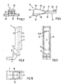
- a part of the housing 1 of a motor vehicle battery is shown schematically, which, in a conventional manner, laterally above its bottom a step 2 , which is preferably formed slightly sloping. It stands on a support plate 3, which projects beyond the housing 1 on this side. On this side of the support plate 3 , a mounting bracket 4 is provided, which may be integrally formed on the support plate 3 or otherwise firmly connected to it. From the mounting bracket 4, which is shown separately again in FIGS. 8 to 10, a long, vertical leg 5 extends parallel and at a distance to the side wall of the housing 1. Preferably, a reinforcing rib 6 is provided on its outer side.
- a shorter, horizontal leg 7 serves for attachment to the support plate 3 and forms at least on the inside of the mounting bracket 4 with the vertical leg 5 a right angle, so that here a horizontal support surface 8 is formed for a separate mounting part 9 , which described below with reference to FIGS. 1 to 3, between the side wall of the housing 1 and the inner surface of the vertical leg 5 of the mounting bracket 4 is inserted and jammed.
- Side walls 10 am vertical leg 5 of the mounting bracket 4 serve on the one hand the stiffening of the bracket 4 and on the other hand securing the fastening part 9.
- An undercut 11 at the free end of the vertical leg 5, which has a small nose 12 at its front edge, serves to clamp the fastening part 9 in the mounting bracket 4 (see below).
- a gradation is provided in the angular range of the mounting bracket 4 on the inside of the vertical leg 5 , which provides a supporting edge 13 for the fastening part 9 .
- FIG. 4 to FIG. 7 show a preferred embodiment of the fastening part 9. It consists of two rectangular sections 14, 15, which are connected to one another by a hinge 16 .
- the upper portion 14 consists of a relatively thin-walled bottom 17 and stiffening side walls 18, which give it the shape of a flat box.
- a slot-shaped opening 19 is provided as a possible engagement for a simple tool, such as a screwdriver.
- free narrow side of the upper portion 14 is on the outside of the bottom 17 extending over the entire width approach 20 provided with a trapezoidal cross-section here, the aligned with the narrow side wall of the portion 14 surface is provided with a transverse ribbing 21 .
- the articulated connection 16 with the lower portion 15 is made at the edge of the opposite narrow side.
- the opposing side walls of the two sections 14, 15 are slightly inclined away from the joint 16 from each other, thus forming an angle which allows an articulated movement between the two sections 14, 15 .
- the second, lower portion 15 consists of a thin-walled bottom 23 with stiffening side walls 24, but the bottom 23 rises from the wall of the upper portion 14 opposite narrow side, so that the lower portion 15 to its free end up to a flattened strip 25 increases in height, from which a steeply sloping, free narrow side 26 is formed, which merges into a vertical support surface 27 .
- wing-like projections 28 may be formed, which serve to stiffen the portion 15 and also enlarge the support surface 27 .
- the housing 1 is placed on the support plate 3 and, for example, as previously, with the formed on one side wall just above its bottom stage (not shown in the drawing) under the resiliently bent edge of a side edge of the support plate 3 is pushed, so here already a fixation is achieved.
- the vertical leg 5 of the mounting bracket 4 is then parallel and at a distance to the opposite side wall of the housing 1.
- the mounting part 9 is now with the lower, at its free end in height increasing portion 15 ahead in the space between the side wall of the housing 1 and the vertical leg 5 of the mounting bracket 4 introduced (see Fig. 1). With the edge of its support surface 27 formed at the free end, there is used to this plant on the located on the side wall of the housing 1 Step 2.
Landscapes
- Chemical & Material Sciences (AREA)
- Chemical Kinetics & Catalysis (AREA)
- Electrochemistry (AREA)
- General Chemical & Material Sciences (AREA)
- Engineering & Computer Science (AREA)
- Mechanical Engineering (AREA)
- Battery Mounting, Suspending (AREA)
- Clamps And Clips (AREA)
- Dry Shavers And Clippers (AREA)
Applications Claiming Priority (3)
| Application Number | Priority Date | Filing Date | Title |
|---|---|---|---|
| DE10230492A DE10230492A1 (de) | 2002-07-06 | 2002-07-06 | Vorrichtung zur Befestigung eines Gehäuses, insbesondere das einer Kraftfahrzeug-Batterie, an einer Trägerplatte |
| DE10230492 | 2002-07-06 | ||
| PCT/EP2003/006010 WO2004006359A2 (de) | 2002-07-06 | 2003-06-07 | Vorrichtung zur befestigung eines gehäuses, insbesondere das einer kraftfahrzeug-batterie, an einer trägerplatte |
Publications (2)
| Publication Number | Publication Date |
|---|---|
| EP1522107A2 EP1522107A2 (de) | 2005-04-13 |
| EP1522107B1 true EP1522107B1 (de) | 2006-01-25 |
Family
ID=29723761
Family Applications (1)
| Application Number | Title | Priority Date | Filing Date |
|---|---|---|---|
| EP03735579A Expired - Lifetime EP1522107B1 (de) | 2002-07-06 | 2003-06-07 | Vorrichtung zur befestigung eines gehäuses, insbesondere das einer kraftfahrzeug-batterie, an einer trägerplatte |
Country Status (7)
| Country | Link |
|---|---|
| US (1) | US7389841B2 (es) |
| EP (1) | EP1522107B1 (es) |
| JP (1) | JP2005535070A (es) |
| AT (1) | ATE316693T1 (es) |
| DE (2) | DE10230492A1 (es) |
| ES (1) | ES2258224T3 (es) |
| WO (1) | WO2004006359A2 (es) |
Families Citing this family (18)
| Publication number | Priority date | Publication date | Assignee | Title |
|---|---|---|---|---|
| DE10314030B4 (de) * | 2003-03-28 | 2005-07-14 | A. Raymond & Cie | Vorrichtung zur Befestigung eines Gehäuses, insbesondere das einer Kraftfahrzueg-Batterie, an einem Träger |
| FR2891515B1 (fr) * | 2005-10-05 | 2008-02-29 | Raymond Et Cie Soc En Commandi | Dispositif de fixation d'une batterie |
| DE102006031461A1 (de) * | 2006-07-07 | 2008-01-10 | Jungheinrich Aktiengesellschaft | Batteriewechselsystem für ein batteriebetriebenes Flurförderzeug |
| DE102007007514B4 (de) * | 2007-02-15 | 2010-02-18 | GM Global Technology Operations, Inc., Detroit | Halteeinrichtung für eine Fahrzeugbatterie |
| FR2952684B1 (fr) * | 2009-11-18 | 2011-12-02 | Peugeot Citroen Automobiles Sa | Dispositif d'immobilisation d'un equipement sur un support, et support d'accessoire(s) associe |
| DE102011009102A1 (de) * | 2011-01-21 | 2012-07-26 | Audi Ag | Batterie mit einer Mehrzahl von Batteriezellen |
| JP6004774B2 (ja) * | 2011-12-16 | 2016-10-12 | モテックス プロダクツ カンパニー リミテッド | 電気自動車用バッテリーの脱着装置 |
| CN103358870B (zh) * | 2012-04-05 | 2016-08-31 | 杭州市电力局 | 一种新能源汽车及其电池锁紧装置 |
| KR101428276B1 (ko) * | 2012-12-12 | 2014-08-07 | 현대자동차주식회사 | 차량용 배터리 트레이 |
| US9517686B1 (en) * | 2015-09-03 | 2016-12-13 | Ford Global Technologies, Llc | Traction battery dual-stage mounting bracket |
| EP3327821B1 (en) * | 2016-01-12 | 2019-10-30 | LG Chem, Ltd. | Battery module assembly having stable fixing means for unit modules |
| JP6544311B2 (ja) * | 2016-07-14 | 2019-07-17 | トヨタ自動車株式会社 | 車載機器固定構造 |
| JP6879182B2 (ja) * | 2017-12-01 | 2021-06-02 | トヨタ自動車株式会社 | バッテリキャリア |
| US11052740B2 (en) | 2018-06-05 | 2021-07-06 | Ford Global Technologies, Llc | Power supply device |
| US10377217B1 (en) * | 2018-06-05 | 2019-08-13 | Ford Global Technologies, Llc | Power supply device |
| US10631429B2 (en) * | 2018-07-13 | 2020-04-21 | Ford Global Technologies, Llc | Vehicle power module assembly |
| DE102021110021A1 (de) | 2021-04-21 | 2022-10-27 | Dr. Ing. H.C. F. Porsche Aktiengesellschaft | Kfz-Starterbatterie-Klemmanordnung |
| JP7380728B2 (ja) * | 2022-03-15 | 2023-11-15 | いすゞ自動車株式会社 | 車両用のバッテリボックスの固定構造および固定方法 |
Family Cites Families (41)
| Publication number | Priority date | Publication date | Assignee | Title |
|---|---|---|---|---|
| US3125177A (en) * | 1964-03-17 | Battery clamping device | ||
| US2009199A (en) * | 1934-05-07 | 1935-07-23 | Milton W Pehotsky | Battery bracket |
| US2453835A (en) * | 1946-08-21 | 1948-11-16 | Willard Storage Battery Co | Battery handle and hold-down bracket |
| US2994395A (en) * | 1958-12-05 | 1961-08-01 | Theodore W Hall | Battery clamp |
| US3165163A (en) * | 1962-05-24 | 1965-01-12 | Ford Motor Co | Battery mounting device |
| DE2037568A1 (de) * | 1970-07-29 | 1972-02-03 | Daimler Benz Ag, 7000 Stuttgart | Vorrichtung zum Befestigen einer Batterie auf ihrer Unterlage |
| US3866704A (en) * | 1973-02-08 | 1975-02-18 | East Penn Manufacturing Compan | Battery holddown |
| US4367572A (en) * | 1980-06-19 | 1983-01-11 | Zielenski Anthony L | Elastic clamping apparatus |
| US4535863A (en) * | 1983-08-26 | 1985-08-20 | Becker John R | Battery security and hold-down device |
| JPS60156053U (ja) * | 1984-03-28 | 1985-10-17 | 日産自動車株式会社 | 自動車バツテリの取付構造 |
| US4854540A (en) * | 1988-02-29 | 1989-08-08 | LTL Industries Ltd. | Vehicle battery mounting apparatus |
| US4846295A (en) * | 1988-04-11 | 1989-07-11 | Amigo Sales, Inc. | Steerable motorized three-wheeled vehicles for use by the handicapped and others desiring assistance |
| FI86926C (fi) * | 1988-04-14 | 1992-10-26 | Neste Oy | Faestmekanism foer ackumulator |
| ES2021909A6 (es) * | 1989-11-28 | 1991-11-16 | Union Plastica Ltda | Sistema de bandeja con aletas resortadas para baterias. |
| US5086860A (en) * | 1990-06-04 | 1992-02-11 | Saturn Corporation | Vehicular battery retainer and shield |
| US5040627A (en) * | 1990-06-14 | 1991-08-20 | Caterpillar Inc. | Mounting apparatus for a battery |
| US5052198A (en) * | 1990-07-30 | 1991-10-01 | Elektrek Partnership | Battery lock and hold-down device |
| DE4110552A1 (de) | 1991-03-30 | 1992-10-01 | Audi Ag | Vorrichtung zum aufnehmen und halten einer starterbatterie |
| US5293951A (en) * | 1991-06-21 | 1994-03-15 | Ronald Scott | Battery safety unit and method |
| US5547160A (en) * | 1993-08-23 | 1996-08-20 | Quick Cable Corporation | Battery holddown |
| US5484667A (en) * | 1993-09-07 | 1996-01-16 | Gnb Battery Technologies Inc. | Spacers for lead-acid batteries |
| US5536595A (en) * | 1994-09-30 | 1996-07-16 | Globe-Union Inc. | Split shell battery enclosure |
| US5543248A (en) * | 1995-02-17 | 1996-08-06 | Globe-Union Inc. | Thermal stabilization shield for storage batteries |
| IL116344A0 (en) | 1995-12-12 | 1996-03-31 | Electric Fuel Ltd | A battery connector unit for use with an electric vehicle and a metal-air battery |
| DE19546556C1 (de) * | 1995-12-13 | 1996-11-28 | Daimler Benz Ag | Befestigungsvorrichtung für eine Batterie im Fahrzeug |
| FR2779010B1 (fr) | 1998-05-19 | 2000-08-04 | Coutier Moulage Gen Ind | Dispositif de fixation d'une batterie d'accumulateurs, notamment pour un vehicule routier |
| US6224998B1 (en) * | 1999-02-04 | 2001-05-01 | Delphi Technologies, Inc. | Battery, tray and heat shield assembly |
| US6161810A (en) * | 1999-02-16 | 2000-12-19 | Delphi Technologies, Inc. | Torsion rod holddown apparatus for a battery |
| FR2796494B1 (fr) * | 1999-07-15 | 2001-10-05 | Coutier Moulage Gen Ind | Dispositif de fixation d'une batterie d'accumulateurs |
| US6230834B1 (en) * | 1999-09-16 | 2001-05-15 | Daimlerchrysler Corporation | Battery mounting system |
| JP4259694B2 (ja) * | 1999-09-29 | 2009-04-30 | 富士重工業株式会社 | 車両用バッテリの搭載構造 |
| US6439329B1 (en) * | 1999-10-08 | 2002-08-27 | Ford Global Tech., Inc. | Integrated battery tray and reservoir assembly |
| US6290013B1 (en) * | 1999-11-18 | 2001-09-18 | Daimlerchrysler Corporation | Battery tray having acid management features |
| US6593027B1 (en) * | 2000-07-27 | 2003-07-15 | Eaton Corporation | Combination battery cover, heat shield and hold down |
| US6521371B1 (en) * | 2000-11-28 | 2003-02-18 | Richard A. Lavanture | Battery tray |
| US6871829B2 (en) * | 2003-01-23 | 2005-03-29 | Quick Cable Corporation | Telescopically adjustable battery holddown |
| US6827169B1 (en) * | 2003-08-01 | 2004-12-07 | Daimlerchrysler Corporation | Force distributing top mount battery retention system |
| US7007767B2 (en) * | 2003-09-11 | 2006-03-07 | Mattel, Inc. | Battery retainer assembly for children's ride-on vehicles |
| US6973987B2 (en) * | 2003-09-11 | 2005-12-13 | Mattel, Inc. | Battery retainer assembly for children's ride-on vehicles |
| US7185724B2 (en) * | 2004-04-05 | 2007-03-06 | Ford Global Technologies, Llc | Battery support structure |
| US7413045B2 (en) * | 2005-11-30 | 2008-08-19 | Karma Medical Products Co., Ltd. | Battery quick-release structure for an electric mobility scooter |
-
2002
- 2002-07-06 DE DE10230492A patent/DE10230492A1/de not_active Withdrawn
-
2003
- 2003-06-07 US US10/520,459 patent/US7389841B2/en not_active Expired - Fee Related
- 2003-06-07 ES ES03735579T patent/ES2258224T3/es not_active Expired - Lifetime
- 2003-06-07 JP JP2004518517A patent/JP2005535070A/ja active Pending
- 2003-06-07 AT AT03735579T patent/ATE316693T1/de not_active IP Right Cessation
- 2003-06-07 DE DE50302298T patent/DE50302298D1/de not_active Expired - Fee Related
- 2003-06-07 EP EP03735579A patent/EP1522107B1/de not_active Expired - Lifetime
- 2003-06-07 WO PCT/EP2003/006010 patent/WO2004006359A2/de not_active Ceased
Also Published As
| Publication number | Publication date |
|---|---|
| US7389841B2 (en) | 2008-06-24 |
| US20050225283A1 (en) | 2005-10-13 |
| WO2004006359A3 (de) | 2004-10-14 |
| ES2258224T3 (es) | 2006-08-16 |
| WO2004006359A2 (de) | 2004-01-15 |
| DE50302298D1 (de) | 2006-04-13 |
| EP1522107A2 (de) | 2005-04-13 |
| ATE316693T1 (de) | 2006-02-15 |
| DE10230492A1 (de) | 2004-01-15 |
| JP2005535070A (ja) | 2005-11-17 |
Similar Documents
| Publication | Publication Date | Title |
|---|---|---|
| EP1522107B1 (de) | Vorrichtung zur befestigung eines gehäuses, insbesondere das einer kraftfahrzeug-batterie, an einer trägerplatte | |
| DE69007819T2 (de) | Montagesystem für Autotelefon. | |
| DE2911094A1 (de) | Plattenverbindungssystem | |
| EP0057879B1 (de) | Kabelbahn als Träger von elektrischen Kabeln | |
| DE69604056T2 (de) | Eckverbindungsvorrichtung für eine rinnenförmige leitung und eine abdeckung wie z.b. eine profilleiste, eine sockelleiste oder eine rinne, insbesondere für ein elektrisches bauteil | |
| EP3529868B1 (de) | Verbindungsanordnung für die verbindung von zwei schaltschrankrahmengestellen | |
| EP3100641B1 (de) | Schubladen-rückwand, schublade und moebel mit einer schublade | |
| WO2004085208A1 (de) | Vorrichtung zur befestigung eines gehäuses, insbesondere das einer kraftfahrzeug-batterie, an einem träger | |
| EP0525541A2 (de) | Kraftfahrzeugleuchte | |
| DE29715114U1 (de) | Baugruppenträger | |
| EP0536471B1 (de) | Montageplatte für Möbelscharniere | |
| EP1072179B1 (de) | Baugruppenträger | |
| DE202007016981U1 (de) | Befestigungsvorrichtung für ein elektrotechnisches Bauteil | |
| DE602005003380T2 (de) | Verfahren zur Montage eines Verstärkungsteils auf die Frontplatte eines Kühl- oder Gefrierschrankes | |
| DE69707753T2 (de) | Verbesserung an Montagesatz für Metallschaltschranktürscharniere | |
| DE3244516A1 (de) | Vorrichtung zur loesbaren verbindung des geraetetraegers mit der schiene einer leuchte, z. b. fuer leuchtstofflampen | |
| DE102009024755A1 (de) | Nummernschildhalterung | |
| EP0903063B1 (de) | Gehäuse | |
| DE9310630U1 (de) | An einer Montagefläche befestigtes elektrisches Gerät | |
| EP1266371B1 (de) | Vorrichtung zur halterung von wendetafeln oder dergleichen | |
| AT390766B (de) | Halter fuer nummerntafel | |
| DE102009033225A1 (de) | Aufhängevorrichtung für Schriftgutbehälter | |
| DE29800872U1 (de) | Anordnung eines Anzeigemoduls auf einer Leiterplatte | |
| EP4181734B1 (de) | Adaptereinheit zur verbindung eines schubkastenbodens mit einer seitenzarge eines schubkastens, seitenzarge und schubkasten | |
| DE69005007T2 (de) | Möbelscharnier. |
Legal Events
| Date | Code | Title | Description |
|---|---|---|---|
| EUG | Se: european patent has lapsed | ||
| PUAI | Public reference made under article 153(3) epc to a published international application that has entered the european phase |
Free format text: ORIGINAL CODE: 0009012 |
|
| AK | Designated contracting states |
Kind code of ref document: A2 Designated state(s): AT BE BG CH CY CZ DE DK EE ES FI FR GB GR HU IE IT LI LU MC NL PT RO SE SI SK TR |
|
| 17P | Request for examination filed |
Effective date: 20050414 |
|
| GRAP | Despatch of communication of intention to grant a patent |
Free format text: ORIGINAL CODE: EPIDOSNIGR1 |
|
| GRAS | Grant fee paid |
Free format text: ORIGINAL CODE: EPIDOSNIGR3 |
|
| GRAA | (expected) grant |
Free format text: ORIGINAL CODE: 0009210 |
|
| AK | Designated contracting states |
Kind code of ref document: B1 Designated state(s): AT BE BG CH CY CZ DE DK EE ES FI FR GB GR HU IE IT LI LU MC NL PT RO SE SI SK TR |
|
| PG25 | Lapsed in a contracting state [announced via postgrant information from national office to epo] |
Ref country code: SK Free format text: LAPSE BECAUSE OF FAILURE TO SUBMIT A TRANSLATION OF THE DESCRIPTION OR TO PAY THE FEE WITHIN THE PRESCRIBED TIME-LIMIT Effective date: 20060125 Ref country code: RO Free format text: LAPSE BECAUSE OF FAILURE TO SUBMIT A TRANSLATION OF THE DESCRIPTION OR TO PAY THE FEE WITHIN THE PRESCRIBED TIME-LIMIT Effective date: 20060125 Ref country code: IE Free format text: LAPSE BECAUSE OF FAILURE TO SUBMIT A TRANSLATION OF THE DESCRIPTION OR TO PAY THE FEE WITHIN THE PRESCRIBED TIME-LIMIT Effective date: 20060125 Ref country code: FI Free format text: LAPSE BECAUSE OF FAILURE TO SUBMIT A TRANSLATION OF THE DESCRIPTION OR TO PAY THE FEE WITHIN THE PRESCRIBED TIME-LIMIT Effective date: 20060125 Ref country code: SI Free format text: LAPSE BECAUSE OF FAILURE TO SUBMIT A TRANSLATION OF THE DESCRIPTION OR TO PAY THE FEE WITHIN THE PRESCRIBED TIME-LIMIT Effective date: 20060125 |
|
| REG | Reference to a national code |
Ref country code: GB Ref legal event code: FG4D Free format text: NOT ENGLISH |
|
| REG | Reference to a national code |
Ref country code: CH Ref legal event code: EP |
|
| REG | Reference to a national code |
Ref country code: IE Ref legal event code: FG4D Free format text: LANGUAGE OF EP DOCUMENT: GERMAN |
|
| GBT | Gb: translation of ep patent filed (gb section 77(6)(a)/1977) |
Effective date: 20060309 |
|
| REF | Corresponds to: |
Ref document number: 50302298 Country of ref document: DE Date of ref document: 20060413 Kind code of ref document: P |
|
| REG | Reference to a national code |
Ref country code: SE Ref legal event code: TRGR |
|
| PG25 | Lapsed in a contracting state [announced via postgrant information from national office to epo] |
Ref country code: DK Free format text: LAPSE BECAUSE OF FAILURE TO SUBMIT A TRANSLATION OF THE DESCRIPTION OR TO PAY THE FEE WITHIN THE PRESCRIBED TIME-LIMIT Effective date: 20060425 Ref country code: BG Free format text: LAPSE BECAUSE OF FAILURE TO SUBMIT A TRANSLATION OF THE DESCRIPTION OR TO PAY THE FEE WITHIN THE PRESCRIBED TIME-LIMIT Effective date: 20060425 |
|
| PG25 | Lapsed in a contracting state [announced via postgrant information from national office to epo] |
Ref country code: PT Free format text: LAPSE BECAUSE OF FAILURE TO SUBMIT A TRANSLATION OF THE DESCRIPTION OR TO PAY THE FEE WITHIN THE PRESCRIBED TIME-LIMIT Effective date: 20060626 |
|
| PGFP | Annual fee paid to national office [announced via postgrant information from national office to epo] |
Ref country code: SE Payment date: 20060629 Year of fee payment: 4 |
|
| PG25 | Lapsed in a contracting state [announced via postgrant information from national office to epo] |
Ref country code: MC Free format text: LAPSE BECAUSE OF NON-PAYMENT OF DUE FEES Effective date: 20060630 Ref country code: BE Free format text: LAPSE BECAUSE OF NON-PAYMENT OF DUE FEES Effective date: 20060630 |
|
| REG | Reference to a national code |
Ref country code: ES Ref legal event code: FG2A Ref document number: 2258224 Country of ref document: ES Kind code of ref document: T3 |
|
| REG | Reference to a national code |
Ref country code: IE Ref legal event code: FD4D |
|
| PLBE | No opposition filed within time limit |
Free format text: ORIGINAL CODE: 0009261 |
|
| STAA | Information on the status of an ep patent application or granted ep patent |
Free format text: STATUS: NO OPPOSITION FILED WITHIN TIME LIMIT |
|
| 26N | No opposition filed |
Effective date: 20061026 |
|
| PG25 | Lapsed in a contracting state [announced via postgrant information from national office to epo] |
Ref country code: AT Free format text: LAPSE BECAUSE OF NON-PAYMENT OF DUE FEES Effective date: 20060607 |
|
| BERE | Be: lapsed |
Owner name: A. RAYMOND & CIE Effective date: 20060630 |
|
| REG | Reference to a national code |
Ref country code: CH Ref legal event code: PL |
|
| EUG | Se: european patent has lapsed | ||
| NLV4 | Nl: lapsed or anulled due to non-payment of the annual fee |
Effective date: 20080101 |
|
| PG25 | Lapsed in a contracting state [announced via postgrant information from national office to epo] |
Ref country code: FR Free format text: LAPSE BECAUSE OF FAILURE TO SUBMIT A TRANSLATION OF THE DESCRIPTION OR TO PAY THE FEE WITHIN THE PRESCRIBED TIME-LIMIT Effective date: 20070316 Ref country code: NL Free format text: LAPSE BECAUSE OF NON-PAYMENT OF DUE FEES Effective date: 20080101 Ref country code: CH Free format text: LAPSE BECAUSE OF NON-PAYMENT OF DUE FEES Effective date: 20070630 Ref country code: GR Free format text: LAPSE BECAUSE OF FAILURE TO SUBMIT A TRANSLATION OF THE DESCRIPTION OR TO PAY THE FEE WITHIN THE PRESCRIBED TIME-LIMIT Effective date: 20060426 Ref country code: LI Free format text: LAPSE BECAUSE OF NON-PAYMENT OF DUE FEES Effective date: 20070630 |
|
| PG25 | Lapsed in a contracting state [announced via postgrant information from national office to epo] |
Ref country code: EE Free format text: LAPSE BECAUSE OF FAILURE TO SUBMIT A TRANSLATION OF THE DESCRIPTION OR TO PAY THE FEE WITHIN THE PRESCRIBED TIME-LIMIT Effective date: 20060125 Ref country code: SE Free format text: LAPSE BECAUSE OF NON-PAYMENT OF DUE FEES Effective date: 20070608 |
|
| PG25 | Lapsed in a contracting state [announced via postgrant information from national office to epo] |
Ref country code: HU Free format text: LAPSE BECAUSE OF FAILURE TO SUBMIT A TRANSLATION OF THE DESCRIPTION OR TO PAY THE FEE WITHIN THE PRESCRIBED TIME-LIMIT Effective date: 20060726 Ref country code: LU Free format text: LAPSE BECAUSE OF NON-PAYMENT OF DUE FEES Effective date: 20060607 |
|
| PG25 | Lapsed in a contracting state [announced via postgrant information from national office to epo] |
Ref country code: CY Free format text: LAPSE BECAUSE OF FAILURE TO SUBMIT A TRANSLATION OF THE DESCRIPTION OR TO PAY THE FEE WITHIN THE PRESCRIBED TIME-LIMIT Effective date: 20060125 Ref country code: FR Free format text: LAPSE BECAUSE OF FAILURE TO SUBMIT A TRANSLATION OF THE DESCRIPTION OR TO PAY THE FEE WITHIN THE PRESCRIBED TIME-LIMIT Effective date: 20060125 |
|
| PGFP | Annual fee paid to national office [announced via postgrant information from national office to epo] |
Ref country code: ES Payment date: 20090601 Year of fee payment: 7 |
|
| PGFP | Annual fee paid to national office [announced via postgrant information from national office to epo] |
Ref country code: CZ Payment date: 20090520 Year of fee payment: 7 Ref country code: IT Payment date: 20090616 Year of fee payment: 7 Ref country code: TR Payment date: 20090601 Year of fee payment: 7 |
|
| PGFP | Annual fee paid to national office [announced via postgrant information from national office to epo] |
Ref country code: DE Payment date: 20090514 Year of fee payment: 7 Ref country code: GB Payment date: 20090513 Year of fee payment: 7 |
|
| GBPC | Gb: european patent ceased through non-payment of renewal fee |
Effective date: 20100607 |
|
| PG25 | Lapsed in a contracting state [announced via postgrant information from national office to epo] |
Ref country code: CZ Free format text: LAPSE BECAUSE OF NON-PAYMENT OF DUE FEES Effective date: 20100607 |
|
| PG25 | Lapsed in a contracting state [announced via postgrant information from national office to epo] |
Ref country code: IT Free format text: LAPSE BECAUSE OF NON-PAYMENT OF DUE FEES Effective date: 20100607 |
|
| PG25 | Lapsed in a contracting state [announced via postgrant information from national office to epo] |
Ref country code: DE Free format text: LAPSE BECAUSE OF NON-PAYMENT OF DUE FEES Effective date: 20110101 |
|
| REG | Reference to a national code |
Ref country code: ES Ref legal event code: FD2A Effective date: 20110715 |
|
| PG25 | Lapsed in a contracting state [announced via postgrant information from national office to epo] |
Ref country code: GB Free format text: LAPSE BECAUSE OF NON-PAYMENT OF DUE FEES Effective date: 20100607 Ref country code: ES Free format text: LAPSE BECAUSE OF NON-PAYMENT OF DUE FEES Effective date: 20110705 |
|
| PG25 | Lapsed in a contracting state [announced via postgrant information from national office to epo] |
Ref country code: ES Free format text: LAPSE BECAUSE OF NON-PAYMENT OF DUE FEES Effective date: 20100608 |
|
| PG25 | Lapsed in a contracting state [announced via postgrant information from national office to epo] |
Ref country code: TR Free format text: LAPSE BECAUSE OF NON-PAYMENT OF DUE FEES Effective date: 20100607 |