EP1522045B1 - Motion artifact correction of tomographical images - Google Patents
Motion artifact correction of tomographical images Download PDFInfo
- Publication number
- EP1522045B1 EP1522045B1 EP03738465.8A EP03738465A EP1522045B1 EP 1522045 B1 EP1522045 B1 EP 1522045B1 EP 03738465 A EP03738465 A EP 03738465A EP 1522045 B1 EP1522045 B1 EP 1522045B1
- Authority
- EP
- European Patent Office
- Prior art keywords
- motion
- image
- images
- pet
- states
- Prior art date
- Legal status (The legal status is an assumption and is not a legal conclusion. Google has not performed a legal analysis and makes no representation as to the accuracy of the status listed.)
- Expired - Lifetime
Links
Images


Classifications
-
- G—PHYSICS
- G06—COMPUTING OR CALCULATING; COUNTING
- G06T—IMAGE DATA PROCESSING OR GENERATION, IN GENERAL
- G06T5/00—Image enhancement or restoration
- G06T5/50—Image enhancement or restoration using two or more images, e.g. averaging or subtraction
-
- A—HUMAN NECESSITIES
- A61—MEDICAL OR VETERINARY SCIENCE; HYGIENE
- A61B—DIAGNOSIS; SURGERY; IDENTIFICATION
- A61B6/00—Apparatus or devices for radiation diagnosis; Apparatus or devices for radiation diagnosis combined with radiation therapy equipment
- A61B6/52—Devices using data or image processing specially adapted for radiation diagnosis
- A61B6/5258—Devices using data or image processing specially adapted for radiation diagnosis involving detection or reduction of artifacts or noise
- A61B6/5264—Devices using data or image processing specially adapted for radiation diagnosis involving detection or reduction of artifacts or noise due to motion
-
- G—PHYSICS
- G06—COMPUTING OR CALCULATING; COUNTING
- G06T—IMAGE DATA PROCESSING OR GENERATION, IN GENERAL
- G06T5/00—Image enhancement or restoration
- G06T5/73—Deblurring; Sharpening
-
- G—PHYSICS
- G06—COMPUTING OR CALCULATING; COUNTING
- G06T—IMAGE DATA PROCESSING OR GENERATION, IN GENERAL
- G06T7/00—Image analysis
- G06T7/20—Analysis of motion
-
- G—PHYSICS
- G06—COMPUTING OR CALCULATING; COUNTING
- G06T—IMAGE DATA PROCESSING OR GENERATION, IN GENERAL
- G06T2207/00—Indexing scheme for image analysis or image enhancement
- G06T2207/10—Image acquisition modality
- G06T2207/10072—Tomographic images
-
- G—PHYSICS
- G06—COMPUTING OR CALCULATING; COUNTING
- G06T—IMAGE DATA PROCESSING OR GENERATION, IN GENERAL
- G06T2207/00—Indexing scheme for image analysis or image enhancement
- G06T2207/20—Special algorithmic details
- G06T2207/20172—Image enhancement details
- G06T2207/20201—Motion blur correction
-
- G—PHYSICS
- G06—COMPUTING OR CALCULATING; COUNTING
- G06T—IMAGE DATA PROCESSING OR GENERATION, IN GENERAL
- G06T2207/00—Indexing scheme for image analysis or image enhancement
- G06T2207/30—Subject of image; Context of image processing
- G06T2207/30004—Biomedical image processing
Definitions
- the invention relates to a method of enhancing the information contents of an image of a moving object.
- the invention also relates to a system in which a method of this kind is carried out as well as to a computer program enabling a data processing unit to carry out such a method. This method is used notably in the field of medical imaging systems.
- a method of this kind is applied wherever images of a moving object are to be formed, which images often contain unavoidable motion artifacts.
- the object is usually imaged in a blurred fashion so that it offers a viewer only inadequate information concerning the object.
- Motion artifacts often give rise to unusable images in particular in the case of slice images or volume images of a moving object.
- US5690106 discloses a method of digital subtraction angiography whereby the contrast and mask sequences are registered based on interpolation prior to subtraction.
- the combination image is formed by special registration of the two individual images while utilizing pregnant, bilateral similarity information contained in both images. Because of the physical circumstances, the PET image contains pronounced motion artifacts which are not taken into account in the disclosed method and give rise to problems during the registration.
- This object is achieved in accordance with the invention by means of a method of enhancing the information contents which can be derived from a first image, containing motion artifacts, of a moving object, which method includes the following steps:
- the first image may have to be reconstructed from projections.
- Motion artifacts are the cause, for example, that the object is imaged less sharply as the object has moved more during the acquisition time. Such motion artifacts may occur when the acquisition time of the imaging method used for the acquisition is long in comparison with the motion, so that the object moves during the acquisition.
- the term "motion" is to be interpreted in a very broad sense.
- the object may perform, for example, a very complex natural motion (human heart) or merely a linear, uniform motion (a sphere rolling at a constant speed).
- At least two further images of the object are involved.
- Each of these images represents a respective state of motion of the object and is as free from motional artifacts as possible, the two states of motions originating from the motion performed by the object during the acquisition of the first image.
- the two states of motions represented may also originate from a motion which has been performed by the object at a different instant and is at least approximately the same as the motion performed by the object during the acquisition of the first image.
- the acquisition time is generally short in comparison with the duration of the motion.
- a motion model of the motion of the object which characterizes states of motion assumed by the object while performing the motion between the two states of motion.
- individual parts of the object move differently during the execution of the motion; for example, some parts of the object travel only a short distance whereas other parts follow a long and possibly curved path.
- the motion model describes the behavior for different parts of the object during the motion from one state of motion to the other.
- the information thus obtained as regards the motion of the object can be incorporated in various ways in supplementary image processing or image forming steps, resulting in a higher quality of the resultant images.
- the intermediate image formed represents the object as if it were to perform the motion. To this end, starting from the two known states of motion, the object motion is imitated by means of the motion model and the intermediate image is formed from this information by superposition. The intermediate image thus reconstructed represents the object with substantially the same motion artifacts as the first image.
- a viewer may wish to view the first image with as few falsifications as possible, despite the motion artifacts contained therein, because information may be lost in the course of known image processing methods.
- the superposition of the intermediate image and the first image so as to form a combination image then offers the advantage that on the one hand the first image is presented with as few falsifications as possible whereas on the other hand the information from the two further images is prepared in the intermediate image in such a manner that it can be combined directly with the information of the first image.
- the combination can be carried out in a variety of manners.
- the two images can be additively superposed, so that the relevant information of the individual images is represented in an overall image.
- the variable division of the combination image constitutes a further possibility, a part of the combination image then being represented by the intermediate image whereas the other part is represented by the first image.
- a viewer can then move the boundary between the two sub-regions, so that an object detail is represented once by the intermediate image and once by the first image.
- the sub-regions can also be displayed so as to be separated by a window, the window being displaceable across the combination image by means of a control unit.
- a simple method of forming the combination image consists in arranging the intermediate image and the first image adjacent one another so that the two images are simultaneously presented to the viewer.
- a motion vector field indicates how or along which path the corresponding part of an object moves while performing the motion between the two known states of motion.
- the generating of the intermediate image is particularly simple in conformity with claim 1.
- Such information can be based, for example, on a model of the motion or be determined by means of a sensor while the motion is performed.
- Such formation of the intermediate image offers the advantage that it is not necessary to describe the entire motion in the motion model, but only information concerning individual states of motion as well as their frequency.
- the object in the intermediate image are differently localized relative to the first image. Relative differences between the object parts themselves as well as absolute differences relative to the image edges or ratio of dimensions of the object parts may then occur.
- the object is represented in the intermediate image with a co-ordinate system which differs from that in the first image.
- the registration as disclosed in claim 3 enables the relevant parts of the object to be transformed either from the positions represented in the intermediate image to the positions represented in the first image or vice versa. All parts of the object are then in the same image positions in the intermediate image as well as in the first image, thus enabling superposition of the two images.
- the use of different modalities enables the representation of different characteristics of the moving object in the corresponding images.
- the method in accordance with the invention is advantageously used in conformity with claim 7 when the first imaging method cannot offer images of a moving object without motion artifacts.
- An image processing system is to be understood to mean any system capable of receiving the images or the data formed by the method in accordance with the invention, of processing these images or data accordingly, and of either visualizing the result or applying it to other systems.
- the image processing system may be completely independent from the devices acquiring the image data by means of the relevant imaging methods.
- the data processing unit may optionally be constructed so as to be programmable.
- the object is also achieved by means of an examination system as disclosed in claim 6.
- the devices for forming the images are well known from prior art so that they will not be elaborated herein.
- a computer program as disclosed in claim 7 enables the data processing unit to carry out a method in accordance with the invention.
- the computer program can be made available to the data processing unit by means of a computer program product such as an external, portable storage medium.
- the Fig. 1 shows the steps of a number of versions of the method in accordance with the invention.
- the rectangular boxes represent results, data, images etc. Steps of the methods are stated within an ellipse.
- Fig. 1 is a diagrammatic representation of the steps and results of a first version of the method. It is an object of the method to acquire images of a moving object by means of two different imaging methods, in this case being methods based on PET and CT.
- the different imaging methods enable different information to be acquired as regards the moving object. Such different information is to be presented in common to a user.
- Projections P1 which have been made, for example, of the thorax of a patient at the area of the diaphragm by means of the PET (Positron Emission Tomography) method are available (the method itself is not shown in Fig. 1 ).
- the PET method is known from the field of nuclear medicine and is intended for the formation of slice images or volume images.
- a metabolic preparation, marked with given, unstable nuclides, is then injected into a patient, said preparation being taken up in a tissue-specific or function-specific manner.
- the radio nuclides used decay, giving rise to two ⁇ quanta in different successive processes in the vicinity of the location of decay, which quanta take off in exactly opposite directions, leave the patient and can be detected by suitable sensors which are arranged in a detector in the form of a ring around the patient.
- the ⁇ quanta On their travel from their location of origin to their point of emergence from the patient the ⁇ quanta traverse further tissue of the patient which can absorb the ⁇ quanta more or less as a function of the type of tissue.
- the ⁇ quanta are attenuated in a tissue-specific manner.
- the whole of detected ⁇ quanta forms a set of projections P1 of the object wherefrom a slice image or volume image can be reconstructed in known manner during a subsequent reconstruction.
- the PET method yields functional images of the object.
- the patient During the acquisition of the projections P1, which may last from a few minutes to one hour, the patient performs a respiratory motion during which the diaphragm moves in conformity with the respiration.
- This respiratory motion causes motion artefacts in the reconstructed PET image I0, said artifacts becoming manifest as an unsharp and blurred image of the object.
- At least two causes of such motion artifacts are known:
- CT Computer Tomography
- CT images contain substantially fewer or no motion artifacts, because the image acquisition can take place substantially faster in relation to the motion.
- Known systems combining PET images with functional information on the object and CT images with anatomical information on the object, ignore the motion artifacts of the PET images upon combination of the information, so that the combined information includes further artifacts or errors. These artifacts or errors are significantly reduced by means of the invention. In the further course of this description it will be demonstrated how artifacts which arise in the PET image due to the above cause 1) are taken into account in the combined information.
- Fig. 5 shows, by way of example, a combination system which consists of a computed tomography apparatus and a PET system.
- the computed tomography apparatus and the PET system are both configured in principle as independent systems which, however, are geometrically coupled relative to a common axis of reference.
- the systems are usually used consecutively; for example, first CT images, representing two striking states of motion, are acquired and subsequently the acquisition of the PET data takes place.
- the computed tomography apparatus includes a gantry 1 which is capable of rotation around an axis of rotation 14 which extends parallel to the z direction. To this end, the gantry 1 is driven at a preferably constant but adjustable angular speed by a motor 2.
- a radiation source S for example, an X-ray tube, is attached to the gantry 1.
- the radiation source is provided with a collimator arrangement 3 which forms a conical radiation beam 4 from the radiation produced by the radiation source S.
- the radiation beam 4 penetrates a moving object (not shown) which is present in a cylindrical examination zone 13. After having traversed the examination zone 13, the X-ray beam 4 is incident on a two-dimensional detector unit 16 attached to the gantry 1.
- the angle of aperture ⁇ max of the radiation beam 4 determines the diameter of the examination zone 13 within which the object to be examined must be present during the acquisition of the measuring values.
- the object which is arranged, for example, on a table in the examination zone 13 can be displaced parallel to the direction of the axis of rotation 14 or the z axis by means of a motor 5.
- the measuring data acquired by the detector unit 16 is applied to a reconstruction unit 10 which reconstructs therefrom the absorption distribution in the part of the examination zone 13 which is covered by the radiation beam 4.
- the two motors 2 and 5, the reconstruction unit 10, the radiation source S and the transfer of the measuring data from the detector unit 16 to the reconstruction unit 10 are controlled by means of a suitable control unit 7.
- the motors 2 and 5 can be controlled in such a manner that the ratio of the speed of propagation of the examination zone 13 to the angular velocity of the gantry 1 is constant, so that the radiation source S and the examination zone 13 move along a helical path, that is, the so-called trajectory, relative to one another. In this case it is irrelevant whether the scanning unit, consisting of the radiation source S and the detector unit 16, or the examination zone 13 performs the rotary motion or the propagation motion, because only the relative motion is of importance. The object is not displaced for the formation of slice images.
- a motion signal is derived by means of an acquisition unit 12 and a motion sensor 15 which is arranged on the object in order to detect the object motion.
- This signal can be applied, if desired, to the reconstruction unit 10 in order to facilitate the selection of the measuring data that is suitable for the reconstruction.
- the motion signal is used (as will be described in detail hereinafter) in accordance with the invention for the determination of the motion model.
- a PET acquisition unit 20 is arranged so as to be concentric with relative to the axis of rotation 14; this unit is arranged as a ring around the object which is present in the examination zone 13.
- the acquisition unit 20 comprises individual sensors 21 which detect the ⁇ quanta emitted by the object.
- the PET acquisition unit In order to form slice images, it suffices to configure the PET acquisition unit so as to be quasi two-dimensional by arranging sensors 21 adjacent one another in a ring-like configuration.
- the PET acquisition unit comprises a plurality of such rings of sensor which are arranged so as to be parallel to one another and around the axis of rotation 13.
- the signals detected by the sensors 21 are applied to an evaluation unit 22 which forms one or more PET images therefrom by means of known algorithms.
- control unit 7 is also arranged to displace the object between the acquisition positions of the CT system as well as those of the PET system. After successful acquisition of the CT data, for example, the object on the table is displaced, by means of the control unit 7 and the motor 5, to the acquisition position of the PET acquisition unit 20 in which the relevant preparation is injected into the object and the PET data is acquired.
- the data processing unit 23 is arranged to combine, using the method in accordance with the invention as well as the motion signal, the information contents of the CT images and the PET images, to reduce motion artifacts, if any, and to visualize the results accordingly by means of a display apparatus 11.
- the data processing unit is constructed so as to be programmable, it is enabled by a computer program to carry out the method in accordance with the invention.
- the computer program may be stored in an internal memory such as, for example, a ROM or an EPROM, or in a computer program product such as a disc or CD-ROM provided with the computer program.
- the computed tomography apparatus shown as well as the PET acquisition unit may be configured in such a manner that slice as well as volume images can be acquired.
- the images I2 and I3 of Fig. 1 represent two different states of motion of the motion performed by the object during the acquisition of the projections P1. Because it is inherent of the method of CT-based acquisition that significantly less time is required than for acquisition on the basis of PET, instantaneous images can be formed of the respiratory motion of the patient, notably the image I2 of the inhaled state and the image I3 of the exhaled state. The inhaled as well as the exhaled state of motion of the patient represents a particularly characteristic state of the respiratory motion.
- a sequence of CT images IS of the respiratory motion can be acquired during which the object performs the same motion as during the acquisition of the projections P1. Subsequently, using known methods, the two images I2 and I3 are extracted from the sequence IS.
- an object motion model M2 is formed in the step C1 in combination with a state of motion function F1.
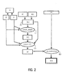
- a state of motion function F1 of this kind is shown in Fig. 3 , by way of example, as a frequency function f(r) for the human respiratory motion.
- the y axis of the frequency function f(r) describes how often the relevant states of motion are assumed by the object while it performs the motion.
- the x axis represents successive states of motion r assumed while the motion is performed.
- the frequency function describes how long on average the object stays in a given state of motion in relation to the other states of motion while the object performs the motion. If the representation is normalized, the integral over this curve produces exactly 1.
- a motion state function F1 which not only provides information as regards the frequency of the assumed states of motion, but also describes the overall motion process (states of motion as well as their frequency and completion in time). Because such a state of motion function is redundant for the use in the next steps of this version, however, it suffices to utilize a frequency function as described above.
- the state of motion function F1 can be derived from a function model M1 without taking into account the actual motion. This is possible notably when in most objects a motion process is very similar or the same.
- the model M1 when in the case of a human respiratory motion the model M1 is formed by the frequency function f(r) of Fig. 1 , it can be considered directly as the state of motion function F1 and be used for determining the motion model M2.
- the actual motion process can be determined by means of an appropriate sensor S1.
- the respiratory motion is determined during the acquisition of the PET projections P1 by means of a respiratory motion sensor provided on the patient and therefrom the frequency function f(r) or, more generally, a state of motion function F1 is derived for the construction of the motion model M2.
- a motion model M2 is derived from the images I2 and I3 and the state of motion function F1.
- Each of the images I2 and I3 represents a respective known state of motion of the object, said states of motion also being present in the state of motion function F1.
- all components of the object move locally linearly during the motion process, that is, along straight paths of different direction and length, between the states of motion shown in the images I2 and I3, for each pixel represented in one of the images I2 or I3 or for each object component the execution of the motion can be determined by means of the state of motion function F1.
- This location-specific motion process can be retained in a motion vector field and constitutes, in conjunction with the state of motion function F1, the motion model M2.
- a motion vector thus indicates the direction in which and the speed at which or the distance over which a pixel or an object component moves during the execution of the motion between each time two states of motion.
- x 3 describes the exhaled state and x 2 describes the inhaled state.
- x 3 describes the exhaled state and x 2 describes the inhaled state.
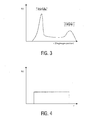
- Fig. 4 shows the frequency function of a motion of an object in which all states of motion are equally frequently assumed during the execution of the motion. This is the case, for example, for the motion where all parts of the object move in the same direction at a constant speed (for example, a bicycle rider).
- the next step C2 aims to form from the images I2 and I3 an image I4 which exhibits substantially the same motion artifacts as the image I0.
- This is achieved in that, starting from one of the images I2 or I3, first artificial images of the remaining states of motion are formed by means of the motion model M2, said artificial images then being superposed so as to form the image I4:
- I ⁇ 4 x ⁇ ⁇ 0 1 f r ⁇ I ⁇ 3 ⁇ x ⁇ 3 + r ⁇ m ⁇ x ⁇ 3 ⁇ dr .
- the image I4 is formed from the integral over all states of motion r of the product of the image I3 and the motion vector field ( x 3 + m ( x 3 )) weighted by the frequency function f(r), the motion vector field ( x 3 + m ( x 3 )) and the frequency function f(r) constituting the motion model M2.
- the image I4 represents a superposition of all states of motion weighted by the relevant duration of stay.
- the image 10a represents the same state of motion as the image I3 and the vectors x a and x 3 as well as the relevant frequency function and the motion model correspond.
- This consideration of the formation of the image I0 is used in the focusing step described hereinafter, because the appearance of the motion artifacts in the image I0 is thus substantiated.
- the images I0 as well as the images I2 and I3 can be acquired by means of two independent systems.
- the object is then positioned in the first apparatus, for example, the PET system, and the PET image is acquired.
- the object is positioned in the second system and the CT images are acquired.
- the object components in the PET image I0 usually are localized differently from those in the CT images I2, I3 and I4, so that only an inadequate direct superposition or direct comparison of the images I4 and I0 can be performed. Therefore, in a step R2 a so-called registration operation is performed.
- step R2 is optional and is not necessary when the co-ordinate system of the images I0 suitably accurately corresponds to that of the images I2 and I3 (as is the case in the system shown in Fig. 5 ). I0 can then be equalized with I5 and the method can be continued as described hereinafter.
- Registration is a generally known method of equalizing co-ordinate systems between two or more images with corresponding structures; a physical correspondence of two identical objects of different contents may then also occur. This is the case, for example, for a functional PET image and an anatomical CT image of the same object.
- the object parts represented in one image can be associated with the corresponding object parts in the other image by the co-ordinate transformation determined. As a result, for example, the object parts shown in one image can be shifted in such a manner that they occupy the corresponding positions of the identical object parts represented in the other image.
- a radioactive source Prior to the injection of the metabolic preparation marked with nuclides, a radioactive source is displaced along a trajectory around the patient for this purpose, said source emitting rays in the direction of the patient which penetrate the patient and are detected by sensors of the PET detector which are situated opposite the radiation source.
- the transmission image subsequently reconstructed is in principle similar to a CT image and, because of the anatomical information contained therein, is better suitable for registration with the CT image, notably in the case of a poor image quality of the actual PET image.
- the co-ordinate transformation between the transmission image and the CT image has been determined, the co-ordinates of the actual PET image and the CT image can be made to correspond, because the co-ordinate systems of the transmission image and the PET image are substantially identical. This method is not shown in Fig. 1 , but can nevertheless be used herein.
- the pixels or the object components of the image I0 can be transformed in the co-ordinate system of the image I4.
- a comparison or a combination of the images I4 and I5 can now be performed, because both images exhibit substantially the same motion artifacts of the object motion and both images represent the object in relation to the same co-ordinate system.
- a viewer, for example, a physician may desire the presentation of the image I0 without falsifications (a co-ordinate transformation in this sense does not represent a falsification) for given applications so as to enable comparison or combination of information therefrom with information from other images.
- Prior art merely offers the possibility of comparing or combining only one of the two images I2 or I3 directly with the image I0.
- the images I2 or I3 do not exhibit motion artifacts, so that on the one hand the searching of a suitable co-ordinate transformation is more difficult and on the other hand the combination or comparison itself is possible only with difficulty.
- step R3 in Fig. 1 Such comparisons or combinations as shown as the step R3 in Fig. 1 are known in principle and can be realized, for example, by superposition, by adjacently arranged images, by partial superposition with manually selectable boundaries or by partial imaging of one image in the other image with manually selectable boundaries.
- the result of the step R3 constitutes the image I6.
- an optional step B1 can be performed for focusing the image I6 which contains artifacts and in which only one state of motion of the motion is represented.
- a known algorithm for focusing which is suitable for linear motions is described in the article by A.K. Katsaggelos "Iterative image restoration algorithms", OPTICAL ENGINEERING, July 1989, Vol. 28, No. 7, p. 735 ff .
- the equation (1) shows how motional unsharpness can in general be expressed by modeling the motion to a linear motion and be compensated in the further course of the method.
- Fig. 2 shows a further possibility, not part of the invention, for enhancing the information contents of an image by means of the motion model.
- a transmission image is acquired by means of the above method, that is, in addition to the actual PET image.
- This transmission image represents the location-specific attenuation of the radioactive radiation.
- This attenuation information is used for the reconstruction R1 of the projections P1 in order to correct the absorption of ⁇ quanta by surrounding tissue (attenuation correction).
- Equation (4) reveals a possibility for multiplying the reconstruction, expressed as a linear reconstruction operator, by the location-specific attenuation information while taking into account distribution effects.
- the reconstruction R5 of the PET image I10 utilizes a transmission image I4 which is formed, as in Fig. 1 , from the CT images I2 and I3 as well as the motion model M2.
- the image I4 contains substantially the same motion artifacts as a PET image which is reconstructed without any attenuation information.
- the motion artifacts in the PET image are taken into account and the reconstruction R5 using the attenuation information from the image I4 produces a qualitatively enhanced image I10 in comparison with a reconstruction utilizing a conventional transmission image.
- the methods of the figs. 1 , and 2 can also be simultaneously used in a system so as to enable presentation of the various results of the methods to a viewer.
- the method of Fig. 2 can be combined at will with the method of Fig. 1 , that is, for as long as the system used is a combination system, because the co-ordinate systems of the PET system correspond substantially to those of the CT system only in the case of a combination system.
- Fig. 1 and Fig. 2 are not limited to CT and PET.
- the method in accordance with the invention in general offers a possibility for comparing images containing different information on a moving object, while taking into account motion artifacts present in an image, applications outside the medical field are also feasible.
- an image of a traveling car which contains motion artifacts can be acquired by means of a thermal-sensitive camera and further images can be acquired by means of customary photographic methods.
- the image of the thermal-sensitive camera shows location-specific functional processes, whereas the photographic images represent structural features of the object.
- the superposition of such different types of information so as to form a combination image while taking into account the motion artifacts advantageously enables the presentation of all information simultaneously to a viewer.
Landscapes
- Engineering & Computer Science (AREA)
- Physics & Mathematics (AREA)
- General Physics & Mathematics (AREA)
- Theoretical Computer Science (AREA)
- Health & Medical Sciences (AREA)
- Life Sciences & Earth Sciences (AREA)
- Medical Informatics (AREA)
- Computer Vision & Pattern Recognition (AREA)
- Optics & Photonics (AREA)
- Molecular Biology (AREA)
- Biophysics (AREA)
- Nuclear Medicine, Radiotherapy & Molecular Imaging (AREA)
- Multimedia (AREA)
- Pathology (AREA)
- Radiology & Medical Imaging (AREA)
- Biomedical Technology (AREA)
- Heart & Thoracic Surgery (AREA)
- High Energy & Nuclear Physics (AREA)
- Surgery (AREA)
- Animal Behavior & Ethology (AREA)
- General Health & Medical Sciences (AREA)
- Public Health (AREA)
- Veterinary Medicine (AREA)
- Apparatus For Radiation Diagnosis (AREA)
- Magnetic Resonance Imaging Apparatus (AREA)
- Measuring And Recording Apparatus For Diagnosis (AREA)
Applications Claiming Priority (3)
| Application Number | Priority Date | Filing Date | Title |
|---|---|---|---|
| DE2002131061 DE10231061A1 (de) | 2002-07-10 | 2002-07-10 | Verfahren und System zur Verbesserung des Informationsgehaltes in einem Bild |
| DE10231061 | 2002-07-10 | ||
| PCT/IB2003/003011 WO2004008390A2 (en) | 2002-07-10 | 2003-07-08 | Motion artifact correction of tomographical images |
Publications (2)
| Publication Number | Publication Date |
|---|---|
| EP1522045A2 EP1522045A2 (en) | 2005-04-13 |
| EP1522045B1 true EP1522045B1 (en) | 2014-11-19 |
Family
ID=29761820
Family Applications (1)
| Application Number | Title | Priority Date | Filing Date |
|---|---|---|---|
| EP03738465.8A Expired - Lifetime EP1522045B1 (en) | 2002-07-10 | 2003-07-08 | Motion artifact correction of tomographical images |
Country Status (6)
| Country | Link |
|---|---|
| US (1) | US7558439B2 (enExample) |
| EP (1) | EP1522045B1 (enExample) |
| JP (1) | JP2005532137A (enExample) |
| AU (1) | AU2003244998A1 (enExample) |
| DE (1) | DE10231061A1 (enExample) |
| WO (1) | WO2004008390A2 (enExample) |
Families Citing this family (34)
| Publication number | Priority date | Publication date | Assignee | Title |
|---|---|---|---|---|
| GB0318701D0 (en) * | 2003-08-08 | 2003-09-10 | Inst Of Cancer Res The | A method and apparatus for image processing |
| WO2005055829A1 (en) * | 2003-12-08 | 2005-06-23 | Philips Intellectual Property & Standards Gmbh | Computer tomography method for objects moving periodically |
| DE102004050172B4 (de) * | 2004-08-20 | 2010-09-02 | "Stiftung Caesar" (Center Of Advanced European Studies And Research) | 3D-Rekonstruktion mit schräger Geometrie |
| US8108024B2 (en) * | 2004-12-15 | 2012-01-31 | Koninklijke Philips Electronics N.V. | Registration of multi-modality images |
| DE102005017492B4 (de) * | 2005-04-15 | 2007-04-19 | Siemens Ag | Verfahren zum rechnerischen Kompensieren einer periodischen Bewegung eines Organs sowie Bildaufnahmesystem |
| DE102005023907A1 (de) | 2005-05-24 | 2006-12-07 | Siemens Ag | Verfahren zur Ermittlung von Positronen-Emissions-Messinformationen im Rahmen der Positronen-Emissions-Tomographie |
| CN101238391B (zh) * | 2005-08-04 | 2012-08-29 | 皇家飞利浦电子股份有限公司 | 功能成像中的运动补偿 |
| JP5377310B2 (ja) * | 2006-08-29 | 2013-12-25 | コーニンクレッカ フィリップス エヌ ヴェ | 胸部ct撮像における心運動アーチファクトの削減 |
| US8548568B2 (en) * | 2006-09-08 | 2013-10-01 | General Electric Company | Methods and apparatus for motion compensation |
| DE102007034956A1 (de) * | 2007-07-26 | 2009-02-05 | Siemens Ag | Verfahren zum Detektieren einer neuropathologisch veränderten Gehirnregion |
| DE102007034953B4 (de) * | 2007-07-26 | 2016-09-22 | Siemens Healthcare Gmbh | Verfahren zur Bewegungsvorgänge berücksichtigenden Aufnahme von Messdaten eines Patienten und zugehörige medizinische Einrichtung |
| US9535145B2 (en) * | 2007-11-09 | 2017-01-03 | Koninklijke Philips N.V. | MR-PET cyclic motion gating and correction |
| US8610965B2 (en) * | 2007-11-26 | 2013-12-17 | Optelec Development B.V. | Reproduction device, assembly of a reproductive device and an indication body, and a method for reproducing an image portion |
| KR100923098B1 (ko) * | 2008-01-15 | 2009-10-22 | (주)이우테크놀로지 | 엑스 레이 씨티 촬영 영상의 메탈 아티팩트를 제거하는방법 |
| CN102265307B (zh) * | 2008-09-17 | 2014-10-22 | 皇家飞利浦电子股份有限公司 | 混合式核/mr成像中使用透射数据的mr分割 |
| WO2010032168A2 (en) * | 2008-09-19 | 2010-03-25 | Koninklijke Philips Electronics N.V. | Method for generation of attenuation map in pet-mr |
| EP2548172A1 (en) | 2010-03-18 | 2013-01-23 | Koninklijke Philips Electronics N.V. | Functional image data enhancement and/or enhancer |
| WO2012079162A1 (en) | 2010-12-15 | 2012-06-21 | University Of British Columbia | Method for generating a 3d representation of an object |
| EP2578148A1 (en) * | 2011-10-04 | 2013-04-10 | Koninklijke Philips Electronics N.V. | Medical imaging system with motion detection |
| EP2792303A4 (en) * | 2011-12-18 | 2015-08-05 | Nat Univ Corp Kyoto Univ | MOTION-TRACKING X-RAY CT IMAGE PROCESSING AND MOTION-TRACKING X-RAY CT IMAGE PROCESSING DEVICE |
| DE102012216759A1 (de) * | 2012-09-19 | 2014-03-20 | Siemens Aktiengesellschaft | Verfahren zur Erzeugung eines PET-Bilddatensatzes eines bewegten Untersuchungsobjekts und Einrichtung hierfür |
| CN104902819B (zh) * | 2013-01-08 | 2018-03-23 | 东芝医疗系统株式会社 | 医用图像诊断装置、核医学诊断装置、x射线ct装置以及病床装置 |
| JP6233980B2 (ja) * | 2013-02-21 | 2017-11-22 | 株式会社日立製作所 | X線ct装置及び画像再構成方法 |
| CN103544681B (zh) * | 2013-08-27 | 2017-06-06 | 清华大学 | 非均一运动模糊图像的恢复方法 |
| US10258301B2 (en) * | 2015-01-05 | 2019-04-16 | Koninklijke Philips N.V. | Digital subtraction angiography |
| DE102015204718A1 (de) | 2015-03-16 | 2016-09-22 | Siemens Healthcare Gmbh | Kompensation von Bildartefakten in einer medizinischen Bildgebung |
| US9905044B1 (en) | 2016-08-25 | 2018-02-27 | General Electric Company | Systems and methods for functional imaging |
| US10993689B2 (en) * | 2017-08-31 | 2021-05-04 | General Electric Company | Method and system for motion assessment and correction in digital breast tomosynthesis |
| US10803633B2 (en) | 2018-02-06 | 2020-10-13 | General Electric Company | Systems and methods for follow-up functional imaging |
| US10740983B2 (en) * | 2018-06-01 | 2020-08-11 | Ebay Korea Co. Ltd. | Colored three-dimensional digital model generation |
| EP3896641A1 (en) * | 2020-04-16 | 2021-10-20 | Siemens Healthcare GmbH | Correcting object movement during mr imaging |
| US11309072B2 (en) | 2020-04-21 | 2022-04-19 | GE Precision Healthcare LLC | Systems and methods for functional imaging |
| US11054534B1 (en) | 2020-04-24 | 2021-07-06 | Ronald Nutt | Time-resolved positron emission tomography encoder system for producing real-time, high resolution, three dimensional positron emission tomographic image without the necessity of performing image reconstruction |
| US11300695B2 (en) | 2020-04-24 | 2022-04-12 | Ronald Nutt | Time-resolved positron emission tomography encoder system for producing event-by-event, real-time, high resolution, three-dimensional positron emission tomographic image without the necessity of performing image reconstruction |
Citations (1)
| Publication number | Priority date | Publication date | Assignee | Title |
|---|---|---|---|---|
| US5690106A (en) * | 1995-06-30 | 1997-11-25 | Siemens Corporate Research, Inc. | Flexible image registration for rotational angiography |
Family Cites Families (15)
| Publication number | Priority date | Publication date | Assignee | Title |
|---|---|---|---|---|
| DE69325508T2 (de) * | 1992-03-09 | 2000-01-27 | St. Georg's Hospital Medical School, London | Neurographische abbildungsverfahren und diffusions-anistropie |
| US5546472A (en) * | 1992-08-07 | 1996-08-13 | Arch Development Corp. | Feature guided method and apparatus for obtaining an image of an object |
| US5361763A (en) * | 1993-03-02 | 1994-11-08 | Wisconsin Alumni Research Foundation | Method for segmenting features in an image |
| US5839440A (en) * | 1994-06-17 | 1998-11-24 | Siemens Corporate Research, Inc. | Three-dimensional image registration method for spiral CT angiography |
| US5647360A (en) * | 1995-06-30 | 1997-07-15 | Siemens Corporate Research, Inc. | Digital subtraction angiography for 3D diagnostic imaging |
| US6088611A (en) * | 1995-08-18 | 2000-07-11 | The Board Of Trustees Of The University Of Illinois | Model based method for high resolution dynamic imaging |
| US5768413A (en) * | 1995-10-04 | 1998-06-16 | Arch Development Corp. | Method and apparatus for segmenting images using stochastically deformable contours |
| US5850486A (en) * | 1996-04-29 | 1998-12-15 | The Mclean Hospital Corporation | Registration of image data |
| US6178271B1 (en) * | 1996-04-29 | 2001-01-23 | The Mclean Hospital Corporation | Methods and systems for registering image data |
| GB9614407D0 (en) * | 1996-07-09 | 1996-09-04 | Secr Defence | Method for imaging artefact reduction |
| US7194117B2 (en) * | 1999-06-29 | 2007-03-20 | The Research Foundation Of State University Of New York | System and method for performing a three-dimensional virtual examination of objects, such as internal organs |
| US5910728A (en) * | 1996-11-12 | 1999-06-08 | Beth Israel Deaconess Medical Center | Simultaneous acquisition of spatial harmonics (SMASH): ultra-fast imaging with radiofrequency coil arrays |
| US6075836A (en) * | 1997-07-03 | 2000-06-13 | University Of Rochester | Method of and system for intravenous volume tomographic digital angiography imaging |
| US6229570B1 (en) * | 1998-09-25 | 2001-05-08 | Lucent Technologies Inc. | Motion compensation image interpolation—frame rate conversion for HDTV |
| US6490476B1 (en) * | 1999-10-14 | 2002-12-03 | Cti Pet Systems, Inc. | Combined PET and X-ray CT tomograph and method for using same |
-
2002
- 2002-07-10 DE DE2002131061 patent/DE10231061A1/de not_active Withdrawn
-
2003
- 2003-07-08 JP JP2004520990A patent/JP2005532137A/ja not_active Withdrawn
- 2003-07-08 AU AU2003244998A patent/AU2003244998A1/en not_active Abandoned
- 2003-07-08 EP EP03738465.8A patent/EP1522045B1/en not_active Expired - Lifetime
- 2003-07-08 WO PCT/IB2003/003011 patent/WO2004008390A2/en not_active Ceased
- 2003-07-08 US US10/520,988 patent/US7558439B2/en not_active Expired - Fee Related
Patent Citations (1)
| Publication number | Priority date | Publication date | Assignee | Title |
|---|---|---|---|---|
| US5690106A (en) * | 1995-06-30 | 1997-11-25 | Siemens Corporate Research, Inc. | Flexible image registration for rotational angiography |
Also Published As
| Publication number | Publication date |
|---|---|
| US7558439B2 (en) | 2009-07-07 |
| WO2004008390A3 (en) | 2004-07-01 |
| EP1522045A2 (en) | 2005-04-13 |
| AU2003244998A8 (en) | 2004-02-02 |
| WO2004008390A2 (en) | 2004-01-22 |
| DE10231061A1 (de) | 2004-01-22 |
| US20050226527A1 (en) | 2005-10-13 |
| JP2005532137A (ja) | 2005-10-27 |
| AU2003244998A1 (en) | 2004-02-02 |
Similar Documents
| Publication | Publication Date | Title |
|---|---|---|
| EP1522045B1 (en) | Motion artifact correction of tomographical images | |
| EP2174294B1 (en) | Motion correction in nuclear imaging | |
| EP3143935B1 (en) | Tomography apparatus and method of reconstructing tomography images | |
| JP5348855B2 (ja) | 対象の画像再構成方法およびその方法を実施するための装置 | |
| CN100573588C (zh) | 使用截短的投影和在先采集的3d ct图像的锥形束ct设备 | |
| CN103390284B (zh) | 在扩展的测量场中的ct图像重建 | |
| CN101496064B (zh) | 用于重构图像的方法和用于重构图像的重构系统 | |
| CN101991428B (zh) | 用于在心脏ct中改进时间分辨率的ct图像重建 | |
| JP5172347B2 (ja) | 反復的制約デコンボリューションによる核医学2次元平面画像の復元 | |
| US20110044559A1 (en) | Image artifact reduction | |
| US8768030B2 (en) | CT measurement with multiple X-ray sources | |
| JP2010501856A (ja) | 動きアーティファクト画像についてのアーティファクト補正 | |
| JP2011507640A (ja) | 希薄化制約補正を用いた画像復元法 | |
| US6751284B1 (en) | Method and system for tomosynthesis image enhancement using transverse filtering | |
| US20080267455A1 (en) | Method for Movement Compensation of Image Data | |
| KR20170105876A (ko) | 단층 촬영 장치 및 그에 따른 단층 영상 재구성 방법 | |
| US10013778B2 (en) | Tomography apparatus and method of reconstructing tomography image by using the tomography apparatus | |
| JP4347651B2 (ja) | マルチ・モダリティ・イメージング方法及び装置 | |
| EP2490180B1 (en) | Medical image processing apparatus and medical image imaging method | |
| KR20180063753A (ko) | 의료 영상 장치 및 동작 방법 | |
| JP2011502683A (ja) | 関心領域の画像を決定するイメージング装置、イメージング方法及びコンピュータプログラム | |
| CN102949201A (zh) | 用于在医学成像中与时相相关地图像重建的方法和装置 | |
| US20070053605A1 (en) | Method for generation of 3-D x-ray image data of a subject | |
| JP2005127837A (ja) | Spect装置及びspect画像再構成方法 | |
| JP2025516727A (ja) | 低線量ctからのx線シミュレーション |
Legal Events
| Date | Code | Title | Description |
|---|---|---|---|
| PUAI | Public reference made under article 153(3) epc to a published international application that has entered the european phase |
Free format text: ORIGINAL CODE: 0009012 |
|
| 17P | Request for examination filed |
Effective date: 20050210 |
|
| AK | Designated contracting states |
Kind code of ref document: A2 Designated state(s): AT BE BG CH CY CZ DE DK EE ES FI FR GB GR HU IE IT LI LU MC NL PT RO SE SI SK TR |
|
| AX | Request for extension of the european patent |
Extension state: AL LT LV MK |
|
| DAX | Request for extension of the european patent (deleted) | ||
| RAP1 | Party data changed (applicant data changed or rights of an application transferred) |
Owner name: PHILIPS INTELLECTUAL PROPERTY & STANDARDS GMBH Owner name: KONINKLIJKE PHILIPS ELECTRONICS N.V. |
|
| 17Q | First examination report despatched |
Effective date: 20061013 |
|
| RAP1 | Party data changed (applicant data changed or rights of an application transferred) |
Owner name: PHILIPS INTELLECTUAL PROPERTY & STANDARDS GMBH Owner name: KONINKLIJKE PHILIPS N.V. |
|
| GRAP | Despatch of communication of intention to grant a patent |
Free format text: ORIGINAL CODE: EPIDOSNIGR1 |
|
| INTG | Intention to grant announced |
Effective date: 20140611 |
|
| GRAS | Grant fee paid |
Free format text: ORIGINAL CODE: EPIDOSNIGR3 |
|
| GRAA | (expected) grant |
Free format text: ORIGINAL CODE: 0009210 |
|
| AK | Designated contracting states |
Kind code of ref document: B1 Designated state(s): AT BE BG CH CY CZ DE DK EE ES FI FR GB GR HU IE IT LI LU MC NL PT RO SE SI SK TR |
|
| REG | Reference to a national code |
Ref country code: GB Ref legal event code: FG4D |
|
| REG | Reference to a national code |
Ref country code: DE Ref legal event code: R081 Ref document number: 60347008 Country of ref document: DE Owner name: PHILIPS GMBH, DE Free format text: FORMER OWNER: PHILIPS INTELLECTUAL PROPERTY &, KONINKLIJKE PHILIPS ELECTRONICS, , NL Ref country code: DE Ref legal event code: R081 Ref document number: 60347008 Country of ref document: DE Owner name: PHILIPS GMBH, DE Free format text: FORMER OWNERS: PHILIPS INTELLECTUAL PROPERTY & STANDARDS GMBH, 20099 HAMBURG, DE; KONINKLIJKE PHILIPS ELECTRONICS N.V., EINDHOVEN, NL |
|
| REG | Reference to a national code |
Ref country code: CH Ref legal event code: EP |
|
| REG | Reference to a national code |
Ref country code: AT Ref legal event code: REF Ref document number: 697401 Country of ref document: AT Kind code of ref document: T Effective date: 20141215 |
|
| REG | Reference to a national code |
Ref country code: IE Ref legal event code: FG4D |
|
| REG | Reference to a national code |
Ref country code: DE Ref legal event code: R096 Ref document number: 60347008 Country of ref document: DE Effective date: 20141231 |
|
| REG | Reference to a national code |
Ref country code: NL Ref legal event code: VDEP Effective date: 20141119 |
|
| REG | Reference to a national code |
Ref country code: AT Ref legal event code: MK05 Ref document number: 697401 Country of ref document: AT Kind code of ref document: T Effective date: 20141119 |
|
| PG25 | Lapsed in a contracting state [announced via postgrant information from national office to epo] |
Ref country code: PT Free format text: LAPSE BECAUSE OF FAILURE TO SUBMIT A TRANSLATION OF THE DESCRIPTION OR TO PAY THE FEE WITHIN THE PRESCRIBED TIME-LIMIT Effective date: 20150319 Ref country code: ES Free format text: LAPSE BECAUSE OF FAILURE TO SUBMIT A TRANSLATION OF THE DESCRIPTION OR TO PAY THE FEE WITHIN THE PRESCRIBED TIME-LIMIT Effective date: 20141119 Ref country code: FI Free format text: LAPSE BECAUSE OF FAILURE TO SUBMIT A TRANSLATION OF THE DESCRIPTION OR TO PAY THE FEE WITHIN THE PRESCRIBED TIME-LIMIT Effective date: 20141119 Ref country code: NL Free format text: LAPSE BECAUSE OF FAILURE TO SUBMIT A TRANSLATION OF THE DESCRIPTION OR TO PAY THE FEE WITHIN THE PRESCRIBED TIME-LIMIT Effective date: 20141119 |
|
| PG25 | Lapsed in a contracting state [announced via postgrant information from national office to epo] |
Ref country code: SE Free format text: LAPSE BECAUSE OF FAILURE TO SUBMIT A TRANSLATION OF THE DESCRIPTION OR TO PAY THE FEE WITHIN THE PRESCRIBED TIME-LIMIT Effective date: 20141119 Ref country code: CY Free format text: LAPSE BECAUSE OF FAILURE TO SUBMIT A TRANSLATION OF THE DESCRIPTION OR TO PAY THE FEE WITHIN THE PRESCRIBED TIME-LIMIT Effective date: 20141119 Ref country code: GR Free format text: LAPSE BECAUSE OF FAILURE TO SUBMIT A TRANSLATION OF THE DESCRIPTION OR TO PAY THE FEE WITHIN THE PRESCRIBED TIME-LIMIT Effective date: 20150220 Ref country code: AT Free format text: LAPSE BECAUSE OF FAILURE TO SUBMIT A TRANSLATION OF THE DESCRIPTION OR TO PAY THE FEE WITHIN THE PRESCRIBED TIME-LIMIT Effective date: 20141119 |
|
| REG | Reference to a national code |
Ref country code: DE Ref legal event code: R082 Ref document number: 60347008 Country of ref document: DE Representative=s name: MEISSNER, BOLTE & PARTNER GBR, DE Ref country code: DE Ref legal event code: R081 Ref document number: 60347008 Country of ref document: DE Owner name: PHILIPS GMBH, DE Free format text: FORMER OWNER: PHILIPS INTELLECTUAL PROPERTY & STANDARDS GMBH, 20099 HAMBURG, DE Ref country code: DE Ref legal event code: R082 Ref document number: 60347008 Country of ref document: DE Representative=s name: MEISSNER BOLTE PATENTANWAELTE RECHTSANWAELTE P, DE |
|
| PG25 | Lapsed in a contracting state [announced via postgrant information from national office to epo] |
Ref country code: EE Free format text: LAPSE BECAUSE OF FAILURE TO SUBMIT A TRANSLATION OF THE DESCRIPTION OR TO PAY THE FEE WITHIN THE PRESCRIBED TIME-LIMIT Effective date: 20141119 Ref country code: SK Free format text: LAPSE BECAUSE OF FAILURE TO SUBMIT A TRANSLATION OF THE DESCRIPTION OR TO PAY THE FEE WITHIN THE PRESCRIBED TIME-LIMIT Effective date: 20141119 Ref country code: CZ Free format text: LAPSE BECAUSE OF FAILURE TO SUBMIT A TRANSLATION OF THE DESCRIPTION OR TO PAY THE FEE WITHIN THE PRESCRIBED TIME-LIMIT Effective date: 20141119 Ref country code: DK Free format text: LAPSE BECAUSE OF FAILURE TO SUBMIT A TRANSLATION OF THE DESCRIPTION OR TO PAY THE FEE WITHIN THE PRESCRIBED TIME-LIMIT Effective date: 20141119 Ref country code: RO Free format text: LAPSE BECAUSE OF FAILURE TO SUBMIT A TRANSLATION OF THE DESCRIPTION OR TO PAY THE FEE WITHIN THE PRESCRIBED TIME-LIMIT Effective date: 20141119 |
|
| REG | Reference to a national code |
Ref country code: DE Ref legal event code: R097 Ref document number: 60347008 Country of ref document: DE |
|
| PLBE | No opposition filed within time limit |
Free format text: ORIGINAL CODE: 0009261 |
|
| STAA | Information on the status of an ep patent application or granted ep patent |
Free format text: STATUS: NO OPPOSITION FILED WITHIN TIME LIMIT |
|
| 26N | No opposition filed |
Effective date: 20150820 |
|
| PG25 | Lapsed in a contracting state [announced via postgrant information from national office to epo] |
Ref country code: IT Free format text: LAPSE BECAUSE OF FAILURE TO SUBMIT A TRANSLATION OF THE DESCRIPTION OR TO PAY THE FEE WITHIN THE PRESCRIBED TIME-LIMIT Effective date: 20141119 |
|
| PG25 | Lapsed in a contracting state [announced via postgrant information from national office to epo] |
Ref country code: MC Free format text: LAPSE BECAUSE OF FAILURE TO SUBMIT A TRANSLATION OF THE DESCRIPTION OR TO PAY THE FEE WITHIN THE PRESCRIBED TIME-LIMIT Effective date: 20141119 Ref country code: SI Free format text: LAPSE BECAUSE OF FAILURE TO SUBMIT A TRANSLATION OF THE DESCRIPTION OR TO PAY THE FEE WITHIN THE PRESCRIBED TIME-LIMIT Effective date: 20141119 |
|
| REG | Reference to a national code |
Ref country code: CH Ref legal event code: PL |
|
| GBPC | Gb: european patent ceased through non-payment of renewal fee |
Effective date: 20150708 |
|
| PG25 | Lapsed in a contracting state [announced via postgrant information from national office to epo] |
Ref country code: LU Free format text: LAPSE BECAUSE OF FAILURE TO SUBMIT A TRANSLATION OF THE DESCRIPTION OR TO PAY THE FEE WITHIN THE PRESCRIBED TIME-LIMIT Effective date: 20150708 |
|
| REG | Reference to a national code |
Ref country code: IE Ref legal event code: MM4A |
|
| PG25 | Lapsed in a contracting state [announced via postgrant information from national office to epo] |
Ref country code: GB Free format text: LAPSE BECAUSE OF NON-PAYMENT OF DUE FEES Effective date: 20150708 Ref country code: CH Free format text: LAPSE BECAUSE OF NON-PAYMENT OF DUE FEES Effective date: 20150731 Ref country code: LI Free format text: LAPSE BECAUSE OF NON-PAYMENT OF DUE FEES Effective date: 20150731 |
|
| REG | Reference to a national code |
Ref country code: FR Ref legal event code: PLFP Year of fee payment: 14 |
|
| PG25 | Lapsed in a contracting state [announced via postgrant information from national office to epo] |
Ref country code: IE Free format text: LAPSE BECAUSE OF NON-PAYMENT OF DUE FEES Effective date: 20150708 |
|
| PG25 | Lapsed in a contracting state [announced via postgrant information from national office to epo] |
Ref country code: BG Free format text: LAPSE BECAUSE OF FAILURE TO SUBMIT A TRANSLATION OF THE DESCRIPTION OR TO PAY THE FEE WITHIN THE PRESCRIBED TIME-LIMIT Effective date: 20141119 Ref country code: HU Free format text: LAPSE BECAUSE OF FAILURE TO SUBMIT A TRANSLATION OF THE DESCRIPTION OR TO PAY THE FEE WITHIN THE PRESCRIBED TIME-LIMIT; INVALID AB INITIO Effective date: 20030708 |
|
| REG | Reference to a national code |
Ref country code: FR Ref legal event code: PLFP Year of fee payment: 15 |
|
| PG25 | Lapsed in a contracting state [announced via postgrant information from national office to epo] |
Ref country code: TR Free format text: LAPSE BECAUSE OF FAILURE TO SUBMIT A TRANSLATION OF THE DESCRIPTION OR TO PAY THE FEE WITHIN THE PRESCRIBED TIME-LIMIT Effective date: 20141119 |
|
| PG25 | Lapsed in a contracting state [announced via postgrant information from national office to epo] |
Ref country code: BE Free format text: LAPSE BECAUSE OF FAILURE TO SUBMIT A TRANSLATION OF THE DESCRIPTION OR TO PAY THE FEE WITHIN THE PRESCRIBED TIME-LIMIT Effective date: 20141119 |
|
| REG | Reference to a national code |
Ref country code: FR Ref legal event code: PLFP Year of fee payment: 16 |
|
| PGFP | Annual fee paid to national office [announced via postgrant information from national office to epo] |
Ref country code: FR Payment date: 20190726 Year of fee payment: 17 |
|
| PGFP | Annual fee paid to national office [announced via postgrant information from national office to epo] |
Ref country code: DE Payment date: 20190930 Year of fee payment: 17 |
|
| REG | Reference to a national code |
Ref country code: DE Ref legal event code: R082 Ref document number: 60347008 Country of ref document: DE Representative=s name: MEISSNER BOLTE PATENTANWAELTE RECHTSANWAELTE P, DE Ref country code: DE Ref legal event code: R081 Ref document number: 60347008 Country of ref document: DE Owner name: PHILIPS GMBH, DE Free format text: FORMER OWNER: PHILIPS GMBH, 20099 HAMBURG, DE |
|
| REG | Reference to a national code |
Ref country code: DE Ref legal event code: R119 Ref document number: 60347008 Country of ref document: DE |
|
| PG25 | Lapsed in a contracting state [announced via postgrant information from national office to epo] |
Ref country code: FR Free format text: LAPSE BECAUSE OF NON-PAYMENT OF DUE FEES Effective date: 20200731 |
|
| PG25 | Lapsed in a contracting state [announced via postgrant information from national office to epo] |
Ref country code: DE Free format text: LAPSE BECAUSE OF NON-PAYMENT OF DUE FEES Effective date: 20210202 |