EP1521627B1 - Gefaltetes filtermaterial und verfahren zu dessen herstellung - Google Patents
Gefaltetes filtermaterial und verfahren zu dessen herstellung Download PDFInfo
- Publication number
- EP1521627B1 EP1521627B1 EP03764291A EP03764291A EP1521627B1 EP 1521627 B1 EP1521627 B1 EP 1521627B1 EP 03764291 A EP03764291 A EP 03764291A EP 03764291 A EP03764291 A EP 03764291A EP 1521627 B1 EP1521627 B1 EP 1521627B1
- Authority
- EP
- European Patent Office
- Prior art keywords
- media
- corrugated
- corrugation
- flute
- sheet
- Prior art date
- Legal status (The legal status is an assumption and is not a legal conclusion. Google has not performed a legal analysis and makes no representation as to the accuracy of the status listed.)
- Revoked
Links
- 238000000034 method Methods 0.000 title claims abstract description 136
- 230000008569 process Effects 0.000 title claims description 103
- 238000004519 manufacturing process Methods 0.000 title claims description 10
- 238000010276 construction Methods 0.000 claims abstract description 58
- 238000007373 indentation Methods 0.000 claims description 116
- 239000000565 sealant Substances 0.000 claims description 52
- 239000012530 fluid Substances 0.000 claims description 37
- 238000003825 pressing Methods 0.000 claims description 7
- 239000012812 sealant material Substances 0.000 claims description 2
- 238000013459 approach Methods 0.000 abstract description 24
- 238000011144 upstream manufacturing Methods 0.000 description 31
- 238000007789 sealing Methods 0.000 description 14
- 239000000463 material Substances 0.000 description 11
- 230000004888 barrier function Effects 0.000 description 10
- 239000011324 bead Substances 0.000 description 9
- 239000000356 contaminant Substances 0.000 description 7
- 238000001914 filtration Methods 0.000 description 6
- 239000007788 liquid Substances 0.000 description 6
- 239000000853 adhesive Substances 0.000 description 5
- 230000001070 adhesive effect Effects 0.000 description 5
- 230000015572 biosynthetic process Effects 0.000 description 5
- 238000005538 encapsulation Methods 0.000 description 5
- 239000007789 gas Substances 0.000 description 5
- 239000011347 resin Substances 0.000 description 4
- 229920005989 resin Polymers 0.000 description 4
- 238000012512 characterization method Methods 0.000 description 3
- 239000000446 fuel Substances 0.000 description 3
- 230000006870 function Effects 0.000 description 3
- 230000004048 modification Effects 0.000 description 3
- 238000012986 modification Methods 0.000 description 3
- 238000003466 welding Methods 0.000 description 3
- 230000008859 change Effects 0.000 description 2
- 230000006835 compression Effects 0.000 description 2
- 238000007906 compression Methods 0.000 description 2
- 238000010924 continuous production Methods 0.000 description 2
- 238000005520 cutting process Methods 0.000 description 2
- 230000000694 effects Effects 0.000 description 2
- 239000012467 final product Substances 0.000 description 2
- 239000012943 hotmelt Substances 0.000 description 2
- 229920002635 polyurethane Polymers 0.000 description 2
- 239000004814 polyurethane Substances 0.000 description 2
- 229920003043 Cellulose fiber Polymers 0.000 description 1
- 238000005452 bending Methods 0.000 description 1
- 230000008901 benefit Effects 0.000 description 1
- 238000002485 combustion reaction Methods 0.000 description 1
- 239000002826 coolant Substances 0.000 description 1
- 239000002657 fibrous material Substances 0.000 description 1
- 230000009477 glass transition Effects 0.000 description 1
- 230000006872 improvement Effects 0.000 description 1
- 230000000977 initiatory effect Effects 0.000 description 1
- 238000005461 lubrication Methods 0.000 description 1
- 230000007246 mechanism Effects 0.000 description 1
- 239000012092 media component Substances 0.000 description 1
- 239000002184 metal Substances 0.000 description 1
- 239000000203 mixture Substances 0.000 description 1
- 239000002245 particle Substances 0.000 description 1
- 239000004033 plastic Substances 0.000 description 1
- 229920003023 plastic Polymers 0.000 description 1
- 238000010248 power generation Methods 0.000 description 1
- 238000012545 processing Methods 0.000 description 1
- 239000000047 product Substances 0.000 description 1
- 238000003908 quality control method Methods 0.000 description 1
- 230000009467 reduction Effects 0.000 description 1
- 238000012552 review Methods 0.000 description 1
- 239000012209 synthetic fiber Substances 0.000 description 1
- 229920002994 synthetic fiber Polymers 0.000 description 1
- 230000007704 transition Effects 0.000 description 1
- 238000009966 trimming Methods 0.000 description 1
Images


Classifications
-
- B—PERFORMING OPERATIONS; TRANSPORTING
- B01—PHYSICAL OR CHEMICAL PROCESSES OR APPARATUS IN GENERAL
- B01D—SEPARATION
- B01D46/00—Filters or filtering processes specially modified for separating dispersed particles from gases or vapours
- B01D46/52—Particle separators, e.g. dust precipitators, using filters embodying folded corrugated or wound sheet material
- B01D46/521—Particle separators, e.g. dust precipitators, using filters embodying folded corrugated or wound sheet material using folded, pleated material
- B01D46/525—Particle separators, e.g. dust precipitators, using filters embodying folded corrugated or wound sheet material using folded, pleated material which comprises flutes
-
- B—PERFORMING OPERATIONS; TRANSPORTING
- B01—PHYSICAL OR CHEMICAL PROCESSES OR APPARATUS IN GENERAL
- B01D—SEPARATION
- B01D25/00—Filters formed by clamping together several filtering elements or parts of such elements
- B01D25/001—Making filtering elements not provided for elsewhere
-
- B—PERFORMING OPERATIONS; TRANSPORTING
- B01—PHYSICAL OR CHEMICAL PROCESSES OR APPARATUS IN GENERAL
- B01D—SEPARATION
- B01D25/00—Filters formed by clamping together several filtering elements or parts of such elements
- B01D25/22—Cell-type filters
- B01D25/24—Cell-type roll filters
-
- B—PERFORMING OPERATIONS; TRANSPORTING
- B01—PHYSICAL OR CHEMICAL PROCESSES OR APPARATUS IN GENERAL
- B01D—SEPARATION
- B01D39/00—Filtering material for liquid or gaseous fluids
-
- B—PERFORMING OPERATIONS; TRANSPORTING
- B01—PHYSICAL OR CHEMICAL PROCESSES OR APPARATUS IN GENERAL
- B01D—SEPARATION
- B01D46/00—Filters or filtering processes specially modified for separating dispersed particles from gases or vapours
- B01D46/0001—Making filtering elements
-
- B—PERFORMING OPERATIONS; TRANSPORTING
- B01—PHYSICAL OR CHEMICAL PROCESSES OR APPARATUS IN GENERAL
- B01D—SEPARATION
- B01D46/00—Filters or filtering processes specially modified for separating dispersed particles from gases or vapours
- B01D46/10—Particle separators, e.g. dust precipitators, using filter plates, sheets or pads having plane surfaces
-
- B—PERFORMING OPERATIONS; TRANSPORTING
- B01—PHYSICAL OR CHEMICAL PROCESSES OR APPARATUS IN GENERAL
- B01D—SEPARATION
- B01D2279/00—Filters adapted for separating dispersed particles from gases or vapours specially modified for specific uses
- B01D2279/60—Filters adapted for separating dispersed particles from gases or vapours specially modified for specific uses for the intake of internal combustion engines or turbines
-
- Y—GENERAL TAGGING OF NEW TECHNOLOGICAL DEVELOPMENTS; GENERAL TAGGING OF CROSS-SECTIONAL TECHNOLOGIES SPANNING OVER SEVERAL SECTIONS OF THE IPC; TECHNICAL SUBJECTS COVERED BY FORMER USPC CROSS-REFERENCE ART COLLECTIONS [XRACs] AND DIGESTS
- Y10—TECHNICAL SUBJECTS COVERED BY FORMER USPC
- Y10T—TECHNICAL SUBJECTS COVERED BY FORMER US CLASSIFICATION
- Y10T156/00—Adhesive bonding and miscellaneous chemical manufacture
- Y10T156/10—Methods of surface bonding and/or assembly therefor
- Y10T156/1002—Methods of surface bonding and/or assembly therefor with permanent bending or reshaping or surface deformation of self sustaining lamina
- Y10T156/1025—Methods of surface bonding and/or assembly therefor with permanent bending or reshaping or surface deformation of self sustaining lamina to form undulated to corrugated sheet and securing to base with parts of shaped areas out of contact
Definitions
- the present disclosure relates to filter media for use in filtering liquids or gases.
- the disclosure particularly relates to such media that utilizes a corrugated structure, to define filtration flutes or surfaces.
- the disclosure relates to techniques for modifying such flutes in selected portions thereof, and to resulting structures.
- Fluid streams such as air and liquid, carry contaminant material therein.
- air flow streams to engines for motorized vehicles or for power generation equipment, gas streams to gas turbine systems and air streams to various combustion furnaces carry particulate contaminant therein that should be filtered.
- liquid streams in engine lube systems, hydraulic systems, coolant systems or fuel systems carry contaminant, that should be filtered. It is preferred for such systems, that selected contaminant material be removed from (or have its level reduced in) the fluid.
- a variety of fluid filter (air or liquid filter) arrangements have been developed for contaminant reduction. In general, however, continued improvements are sought.
- JP 1171615 describes a technique for closing the ends of fluids in a filter arrangement.
- the corrugated filter members are folded to form a folding portion such that end portions of their crest portions are in close contact with adjacent flat member, respectively, where as by means of the folding portion an end portion of each crest portion is closed.
- the present disclosure concerns folded flute ends of fluted filter media, and to techniques for folding. It also concerns preferred filter arrangements constructed utilizing media having flutes with folded ends.
- the media folding includes a step of deforming a media flute, typically through an indentation or projection against an outside surface of the flute.
- follow up folding steps cause preferred folded configurations to result.
- Fluted filter media can be used to provide fluid filter constructions in a variety of manners.
- One well known manner is as a z-filter construction.
- the term "z-filter construction" as used herein, is meant to refer to a filter construction in which individual ones of corrugated, folded or otherwise formed filter flutes are used to define sets of parallel longitudinal inlet and outlet filter flutes for fluid flow through the media.
- Some examples of z-filter media are provided in U.S. patents 5,820,646 ; 5,772,883 ; 5,902,364 ; 5,792,247 ; 5,895,574 ; 6,210,469 ; 6,190,432 ; 6,350,296 ; 6,179,890 ; 6,235,195 ; Des. 399,944 ; Des. 428,128 ; Des. 396,098 ; Des. 398,046 ; D437,401 .
- One particular type of z-filter media utilizes two specific media components joined together, to form the media construction.
- the two components are: a corrugated (or fluted) sheet; and, a non-corrugated (or facing) sheet.
- the corrugated (or fluted) media and non-corrugated (or facing) sheet together are used to define the parallel inlet and outlet flutes.
- the corrugated sheet and non-corrugated sheet are secured together and are then coiled to form a z-filter media construction.
- Such arrangements are described, for example, in U.S. 6,235,195 and 6,179,890 .
- some non-coiled sections of corrugated media secured to flat media are stacked on one another, to create a filter construction. An example of this is described in Fig. 11 of 5,820,646 .
- corrugated used herein to refer to structure in media, is meant to refer to a structure resulting from passing the media between two corrugation rollers, i.e., into a nip or bite between two rollers each of which has surface features appropriate to cause a corrugation affect in the resulting media.
- corrugation is not meant to refer to flutes that are folded or otherwise formed by techniques not involving passage of media into a bite between corrugation rollers.
- corrugated is meant to apply even if the media is further modified or deformed after corrugation, for example by the folding techniques described herein.
- Corrugated media is a specific form of fluted media.
- Fluted media is media which has individual flutes (for example formed by corrugating or folding) extending thereacross.
- Serviceable filter element configurations utilizing z-filter media are sometimes referred to as "straight through flow configurations" or by variants thereof.
- the serviceable filtered elements generally have an inlet flow face and an opposite exit flow face, with flow entering and exiting the filter cartridge in generally the same straight through direction.
- the term "serviceable” in this context is meant to refer to a media containing filter cartridge that is periodically removed and replaced from a corresponding fluid cleaner.
- the straight through flow configuration is in contrast to serviceable filter cartridges such as cylindrical pleated filter cartridges of the type shown in U.S. Patent No. 6,039,778 , in which the flow generally makes a turn as its passes through the serviceable cartridge. That is, in a 6,039,778 filter the flow enters the cylindrical filter cartridge through a side, and then turns to exit through an end face (in forward-flow systems). In reverse-flow systems, the flow enters the serviceable cylindrical cartridge through an end face and then turns to exit through a side of the filter cartridge. An example of a reverse-flow system is shown in U.S. Patent No. 5,613,992 .
- FIG. 1 is based on the disclosure of prior art U.S. patent 5,820,646 , at Fig. 1 .
- Fig. 2 is an enlarged end view of an inlet end portion of a straight through flow filter element using a media construction made with the media shown in Fig. 1 .
- Fig. 3 is an enlarged end view of and analogous to Fig. 2 , but of an opposite, outlet, end.
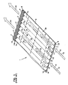
- Fig. 4 is an enlarged, schematic, view of a combination of corrugated sheet and non-corrugated sheets.
- z-filter media construction and variants thereof as used herein, is meant to refer to any or all of: a web of corrugated or otherwise fluted media secured to non-corrugated (facing) media with appropriate sealing to allow for definition of inlet and outlet flutes; or, such a media coiled or otherwise constructed or formed into a three dimensional network of inlet and outlet flutes; and/or, a filter construction including such media.
- the z-filter media construction 1 depicted comprises a corrugated sheet 3, and a non-corrugated sheet 4 secured to one another.
- the corrugated sheet 3 is secured to the non-corrugated sheet 4 such that individual flutes or corrugations 7 (comprising ridges 7a and troughs 7b when viewed toward side 3a of sheet 3) extend across the non-corrugated sheet 4 between opposite ends or edges 8 and 9.
- end (or edge) 8 or end (or edge) 9 is the upstream end or edge.
- edge 8 is chosen to be the upstream edge
- edge 9 is chosen to be the downstream edge, in the resulting filter media construction.
- arrows 10 indicate the direction of fluid flow, during filtering.
- the corrugated sheet 3 has first and second opposite sides or surfaces 3a, 3b.
- the second side 3b is the side directed toward the non-corrugated sheet 4, during initial assembly of the corrugated sheet 3/flat sheet 4 combination as discussed below; i.e., when the corrugated sheet 3 is first brought into contact with the non-corrugated sheet 4.
- flutes 11 defined by troughs 7b of the corrugations 7 above the corrugated sheet 3, i.e., at side 3a of sheet 3 are open to fluid flow therein in the direction of arrows 12, along the upstream edge 8, but are closed to fluid flow therefrom along the downstream edge 9, by barrier 14, in this instance sealant 14a.
- flutes 15, defined by corrugations 7a on the opposite side 3b of the corrugated sheet 3 from flutes 11, are closed to entrance of fluid therein along the upstream edge 8, by barrier 16, in this instance sealant 16a, but are open to fluid flow outwardly therefrom, along edge 9, by the absence of any sealant at this location.
- the media is shown not secured in an overall three-dimensional filter element cartridge structure, that would complete creation of the isolated parallel flutes 11, 15.
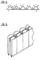
- This is shown in fragmentary, schematic, in Fig. 2 .
- the media construction 1 is now shown configured in an overall three-dimensional media pack 20.
- media pack 20 for the embodiment shown, would comprise the media construction 1 of Fig. 1 , coiled about itself to create a cylindrical fluted construction 21.
- a complete drawing would typically show a circular or obround filter body.
- Fig. 2 only a portion of such a coiled construction 21 is depicted, in particular a portion when viewed toward an upstream surface 22.
- upstream when used in this or similar contexts to refer to a surface or edge, is meant to refer to the surface or edge toward which fluid is directed, for a filtering process. That is, the upstream surface or edge is the surface or edge at which the fluid to be filtered enters the z-filter construction 21.
- downstream when used to refer to an edge or surface, is meant to refer to the edge or surface of a construction 21 from which filtered fluid exits the filtered media construction 21, during use.
- Figs. 2 and 3 the flutes 11, 15 are depicted schematically, as if they have triangular, cross-sections, for simplicity.
- the actual curved shape of Fig. 1 would be present in the actual filter.
- inlet flutes 11 are open to the passage of fluid flow therein.
- the closed upstream ends of exit flutes 15 are also shown, by the presence of a barrier, in this instance sealant.
- fluid flow directed against upstream surface 22 can only pass into the media construction 20, for filtering, by entering the inlet flutes 11.
- the outlet flutes may not be sealed immediately at the edge 8, but rather may be sealed by a sealant spaced inwardly from the edge 8, a portion of the way down the length of the corresponding flute.
- the exit edge 9 of the media, forming exit end or 23 of the filter construction 21 The exit flutes 15 are shown open, and the inlet flutes 11 are shown closed by barrier or sealant.
- the inlet flutes 11 will be considered sealed at the downstream ends, as long as the sealant material or other structure closing the flute, is at the exit edge 9, or within a distance from the edge 9 corresponding to no more than 25% of the distance between the opposite edges 8 and 9.
- the sealed end of each flute 8, 9 would be sealed by sealant positioned at a location within a distance from the closest edge of no more than 10% of the flute length from edge 8 to edge 9.
- the sealing is at the edge 9.
- the description "no more than 25% (or 10%) of the flute length from edge 8 to edge 9" in this context, is meant to include sealing at edge 9.
- the corrugated sheet 3, Fig. 1 is of a type generally characterized herein as having a regular, curved, wave pattern of flutes or corrugations.
- wave pattern in this context, is meant to refer to a flute or corrugated pattern of alternating troughs 7b and ridges 7a.
- regular in this context is meant to refer to the fact that the pairs of troughs and ridges (7b, 7a) alternate with generally the same repeating corrugation (or flute) shape and size.
- each trough 7b is substantially an inverse of each ridge 7a.
- the term “regular” is thus meant to indicate that the corrugation (or flute) pattern comprises troughs and ridges with each pair (comprising an adjacent trough and ridge) repeating, without substantial modification in size and shape of the corrugations along at least 70% of the length of the flutes.
- substantially in this context, refers to a modification resulting from a change in the process or form used to create the corrugated or fluted sheet, as opposed to minor variations from the fact that the media sheet 3 is flexible.
- ridges and troughs are present.
- the media could be terminated, for example, between a pair comprising a ridge and a trough, or partially along a pair comprising a ridge and a trough.
- the media 1 depicted in fragmentary has eight complete ridges 7a and seven complete troughs 7b.
- the ends of the troughs and ridges may vary from one another. Such variations in ends are disregarded in the definitions.
- curved is meant to refer to a corrugation pattern that is not the result of a folded or creased shape provided to the media, but rather the apex 7a of each ridge and the bottom 7a of each trough is formed along a radiused curve.
- a typical radius for such z-filter media would be at least .25 mm and typically be not more than 3 mm.
- An additional characteristic of the particular regular, curved, wave pattern depicted in Fig. 4 , for the corrugated sheet 3, is that at approximately a midpoint 30 between each trough and each adjacent ridge, along most of the length of the flutes, is located a transition region where the curvature inverts.
- trough 7b is a concave region
- ridge 7a is a convex region.
- trough 7b of side 3a forms a ridge
- ridge 7a of face 3a forms a trough.
- a characteristic of the particular regular, curved, wave pattern corrugated sheet shown in Figs. 1-4 is that the individual corrugations are generally straight.
- straight in this context, it is meant that through at least 70%, typically at least 80% of the length between edges 8 and 9, the troughs do not change substantially in cross-section.
- the term "straight" in reference to corrugation pattern shown in Figs. 1-4 in part distinguishes the pattern from the tapered flutes of corrugated media described in Fig. 1 of WO 97/40918 .
- the tapered flutes of Fig. 1 of WO 97/40918 would be a curved wave pattern, but not a "regular” pattern, or a pattern of straight flutes, as the terms are used herein.
- the parallel corrugations are generally straight completely across the media, from edge 8 to edge 9.
- straight flutes or corrugations are deformed or folded at selected locations, especially at ends. Again, modifications at flute ends are generally disregarded in the above definitions of "regular,” “curved” and “wave pattern.”
- FIG. 3 Attention is again directed to Fig. 3 in which media pack 20 is depicted from a viewpoint directed toward downstream end 23 defined by edge 9 of the z-filter media construction 1.
- the exit flutes 15 are depicted open and unsealed, and the entrance flutes 11, are shown closed by a barrier, in this case, by sealant.
- the only way fluid can exit from downstream end 23 is by flow outwardly from an open exit flute 15.
- the media is either surrounded by an impermeable shell (as in U.S. Patent No. 5,820,646 ), or seals are used at appropriate locations, or both, to prevent fluid flow from going around the media, from a fluid inlet to a fluid outlet.
- Fig. 4 is an enlarged, fragmentary, schematic, end view of the Z-filter media construction 1, showing the corrugated sheet 3 and the non-corrugated sheet 4, but not barrier or sealant.
- the configuration of the corrugated sheet, in Fig. 4 will sometimes be referred to herein as a regular, curved, wave pattern of straight flutes.
- the filter media is a relatively flexible material, typically a non-woven fibrous material (of cellulose fibers, synthetic fibers or both) typically including a resin therein, sometimes treated with additional materials.
- a non-woven fibrous material typically of cellulose fibers, synthetic fibers or both
- a resin typically including a resin therein, sometimes treated with additional materials.
- it can be conformed or configured into the various folded or corrugated patterns, without unacceptable media damage.
- it can be readily coiled or otherwise configured for use, again without unacceptable media damage.
- it must be of a nature such that it will maintain a corrugated or folded configuration, during use.
- the media contains a resin.
- the media can be heated to above the glass transition point of the resin. When the resin then cools, it will help to maintain the fluted shapes.
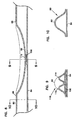
- Yamada, et al. suggest addressing this issue at the downstream end of the media, by flattening the two media sheets together into a parallel configuration, see Figs. 1 and 4 of Yamada, et al, 5,562,825 .
- Yamada, et al. Fig. 4 is depicted herein as Fig. 5 , without reference numerals.
- a flattening such as that found in Yamada, et al., leads to less sealant volume due to the crushing and potentially less leakage through the sealant, due to the compression.
- a reference which generally shows a different type of crushing of flutes is GB. 703,823, published February 10, 1954 .
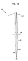
- a z-filter media construction 40 utilizing a regular, curved, wave pattern corrugated sheet 43, and a non-corrugated flat sheet 44, is depicted.
- the distance D1 between points 50 and 51 defines the extension of flat media 44 in region 52 underneath a given corrugated flute 53.
- the length D2 of the arcuate media for the corrugated flute 53, over the same distance D1 is of course larger than D1, due to the shape of the corrugated flute 53.
- the linear length D2 of the media 53 between points 50 and 51 will generally be at least 1.2 times D1.
- D2 would be within a range of 1.2 - 2.0, inclusive.
- D2 is about 1.25 - 1.35 x D1.
- Such media has, for example, been used commercially in Donaldson PowercoreTM Z-filter arrangements.
- the ratio D2/D1 will sometimes be characterized as the flute/flat ratio or medium draw for the corrugated media.
- DCI A Flute: Flute/flat 1.52:1;
- DCI B Flute: Flute/flat 1.32:1;
- E Flute: Flute/flat 1.24:1;
- X Flute: Flute/flat 1.29:1;
- a Flute: Flute/flat 1.53:1;
- standard flute configurations from the corrugated box industry can be used to define corrugation shapes or approximate corrugation shapes for corrugated media. Comparisons above between the DCI A flute and DCI B flute, and the corrugation industry standard A and standard B flutes, indicate some convenient variations.
- Donaldson Company the assignee of the present disclosure, has determined that when the relationship between the flutes of corrugation sheet and the flat sheet is such that the flute/flat ratio or medium draw is at least 1.2 (i.e. the corrugation length (D2) is at least 1.2 times the linear flat sheet length (D1) in the region of closure, in some instances it is preferred to generate a regular fold pattern, to collapse the corrugation (flute) toward the flat sheet, and to reduce the sealant area at or near flute ends.
- regular fold pattern in this context, it is meant that selected corrugated (flute) ends that are modified are folded into a regular and repeated pattern, as opposed to merely being crushed toward the flat sheet.
- regular fold pattern is illustrated herein in Fig.
- Such a fold pattern will generally be referred to herein as a "center darted” or “center dart” fold pattern, since it results from creating, a dart or indentation (deformation) at or near an apex of each flute, to be closed, with a follow-up step of folding.
- a pattern of fold steps that accomplishes this is discussed below in connection with Figs. 7-24 , and also in connection with Figs. 28-47 .
- an end of a flute or corrugation will be characterized as closed by a "fold” or as being “folded” if it includes at least two creases therein, each crease resulting in a portion of the media being folded back on or over itself.
- the fold pattern in Fig. 15 has four such creases, discussed below.
- Preferred configurations include at least four folds or creases.
- the term "fold” is intended to be applicable, even if, when the media is folded back over itself, some structure or material, such as sealant, is positioned between adjacent layers of media.
- FIG. 7 one example of a manufacturing process for making center darts is shown schematically at 60.
- the non-corrugated sheet 64 and the corrugated sheet 66 having flutes 68 are brought together to form a media web 71.
- the darting process occurs at station 70 to form center darted section 72 located mid-web.
- the z-filter media or Z-media 74 can be cut along the center darted section 72 to create two pieces 76, 77 of Z-media 74, each of which has an edge with a set of corrugations having folded ends.
- Fig. 7 it is noted that the process depicted generally involves formation of darts through folds occurring on a mid-line 73 of an associated media web 71. Such a process will be generally characterized herein as a “mid-web folding" or “mid-web darting” process. This is to distinguish from an edge folding or edge darting process, described below. Of course, the mid-web folding process shown in Fig. 7 is used to generate edge folds, once the web 71 is slit along fold line 73.
- the process of deforming the flutes 68, as part of generating a regular fold pattern, takes place at station 70.
- the folding process shown in general, involves inverting the ridges 80 of the flutes 68 and then pressing (or folding) the inverted ridges 80 against the non-corrugated sheet 64 to form the center darted section 72.
- An indenting, inverting, or darting wheel 84 operates first to deform or invert the ridges 80, while a folder wheel 86 later presses or folds the inversions made by the darting wheel 84 into the non-corrugated sheet 64 to form the darted section 72.
- Fig. 7 also shows an optional manipulation to the corrugated sheet 66 before encountering the darting wheel 86.
- the optional media manipulation includes engagement with a creaser wheel 88.
- the optional creaser wheel 88 engages the flutes 68 by initially nicking or temporarily deforming by pressing inwardly the ridges 80 toward the uncorrugated sheet 64. This can help to start the process of deformation and to help the flutes 68 to be appropriately deformed (inverted) by the darting wheel 86.
- a splitter, blade or cutter is shown at 90 dividing the Z-media 74 into pieces 76, 77.
- the Z-media 74 is formed. In the schematic shown in FIG. 7 , this is done by passing a flat sheet of media 92 through a pair of corrugation rollers 94, 95.
- the flat sheet of media 92 is unrolled from a roll 96, wound around tension rollers 98, and then passed through a nip or bite 102 between the corrugation rollers 94, 95.
- the corrugation rollers 94, 95 have teeth 104 that will give the general desired shape of the corrugations after the flat sheet 92 passes through the nip 102.
- the flat sheet 92 becomes corrugated and is referenced at 66 as the corrugated sheet.
- the corrugated sheet 66 is routed to the darting process 70.
- a preferred corrugation pattern will be a regular curved wave pattern corrugation, of straight flutes, as defined herein above. In some instances the techniques may be applied with curved wave patterns that are not "regular" and do not use straight flutes.
- the process also shows the non-corrugated sheet 64 being routed to the darting process station 70.
- the non-corrugated sheet 64 is depicted as being stored on a roll 106 and then directed to the corrugated sheet 66 to form the Z-media 74.
- the corrugated sheet 66 and the non-corrugated sheet 64 are secured together at some point in the process, by adhesive or by other means (for example by sonic welding).
- Fig. 7 can be used to create the center darted section 72.
- Figs. 8 - 10 show one of the flutes 68 after initial deformation; e.g., after engaging the indenting or darting wheel 84 and before engaging the folder wheel 86.
- the darting wheel 84 deforms a portion 69 of the ridge 80, by indenting or inverting it.
- inverting and variants thereof, it is meant that the ridge 80 is indented or turned inward in a direction toward the non-corrugated sheet 64.
- Fig. 9 is a cross-sectional view along the mid-point of the inversion 110 created by the darting wheel 84.
- the inversion 110 is between a pair of peaks 112, 114 that are created as a result of the darting process.
- the peaks 112, 114 together form a flute double peak 116.
- the peaks 112, 114 in the flute double peak 116 have a height that is shorter than the height of the ridge 80 before inversion.
- Fig. 10 illustrates the cross-section of the flute 68 at a portion of the flute 68 that did not engage the darting wheel 84, and thus was not deformed. As can be seen in Fig. 10 , that portion of the flute 68 retains its original corrugated shape.
- FIGs. 7-24 The particular process illustrated in Figs. 7-24 , is one of "center indenting,” “center inverting,” “center darting” or “center deformation.”
- center in this context, again, it is meant that the indentation or inversion occurred at an apex or center of the associated ridge 80, engaged by the indenting or darting wheel 84.
- a deformation or indent will typically be considered herein to be a center indent, as long as it occurs within 3 mm of the center of a ridge.
- crease means to indicate an edge formed by folding the media back on or over itself, with or without sealant or adhesive between portions of the media.
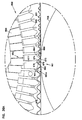
- FIGS. 11 - 15 show sections of the darted section 72 after engagement with the folder wheel 86.
- FIG. 15 shows an end view of the darted section 72, in cross-section.
- a fold arrangement 118 can be seen to form a darted flute 120 with four creases 121a, 121b, 121c, 121d.
- the fold arrangement 118 includes a flat first layer 122 that is secured to the non-corrugated sheet 64.
- a second layer 124 is shown pressed against the flat first layer 122.
- the second layer 124 is preferably formed from folding opposite outer ends 126, 127 of the first layer 122.
- FIG. 15 two of the folds or creases 121a, 121b will generally be referred to herein as "upper, inwardly directed" folds or creases.
- the term “upper” in this context is meant to indicate that the creases lie on an upper portion of the entire fold 120, when the fold 120 is viewed in the orientation of Fig. 15 .
- the term “inwardly directed” is meant to refer to the fact that the fold line or crease line of each crease 121a, 121b, is directed toward the other.
- creases 121c, 121d will generally be referred to herein as “lower, outwardly directed” creases.
- the term “lower” in this context refers to the fact that the creases 121c, 121d are not located on the top as are creases 121a, 121b, in the orientation of Fig. 15 .
- the term “outwardly directed” is meant to indicate that the fold lines of the creases 121c, 121d are directed away from one another.
- upper and lower as used in this context are meant specifically to refer to the fold 120, when viewed from the orientation of Fig. 15 . That is, they are not meant to be otherwise indicative of direction when the fold 120 is oriented in an actual product for use.
- a preferred regular fold arrangement 118 according to Fig. 15 in this disclosure is one which includes at least two "upper, inwardly directed, creases.” These inwardly directed creases are unique and help provide an overall arrangement at which the folding does not cause a significant encroachment on adjacent flutes. These two creases result in part from folding tips 112, 114, Fig. 9 , toward one another.
- a third layer 128 can also be seen pressed against the second layer 124.
- the third layer 128 is formed by folding from opposite inner ends 130, 131 of the third layer 128.
- the non-corrugated sheet 64 will be secured to the corrugated sheet 66 along the edge opposite from the fold arrangement 118.
- the first layer 122 includes the inverted ridge 110.
- the second layer 124 corresponds to the double peak 116 that is folded toward, and in preferred arrangements, folded against the inverted ridge 110. It should be noted that the inverted ridge 110 and the double peak 116, corresponding to the second layer 124, is outside of the troughs 82 on opposite sides of the ridge 80.
- FIGS. 12 - 14 show the shape of the flute 68 at different sections.
- FIG. 14 shows an undeformed section of the flute 68.
- the inversion 110 can be seen in FIGS. 12 and 13 extending along from where it engages the non-corrugated sheet 64 ( FIG. 15 ) to a point where it no longer exists ( FIG. 14 ). In FIGS. 12 and 13 , the inversion 110 is spaced at different lengths from the non-corrugated sheet 64.
- Fig. 16 illustrates one embodiment of creaser wheel 88 that is optionally used with the process 70.
- the creaser wheel 88 when used, is oriented such that its axis of rotation 136 is oriented parallel to the flute direction. This means that the creaser wheel 88 rotates in a plane that is in a direction transverse to the flute length.
- the creaser wheel 88 depicted is shown with its axis of rotation 136 passing centrally therethrough.
- the creaser wheel 88 is generally tapered at opposite surfaces 137, 138 from a central region 139 adjacent to the central axis 136 extending to an end region 140.
- the end region 140 is narrow, when compared to the width across the creaser wheel 88 at central region 139. In the example shown, the end region 140 is less than one-half the width across the creaser wheel 88 at the central region 139. In many embodiments, the width across the end region 140 is less than one-third of the width across the central region 139. In the example embodiment illustrated, the tapered surfaces 137, 138 are tapered at an angle a less than 10°, at least 1°, and in the particular example, 3 - 6°.
- the creaser wheel 88 is optionally used to initially nick the flute 68.
- the creaser wheel 88 rotates about the axis 136 in the direction of movement of the corrugated sheet 66.
- the end region 140 contacts the ridges 80 of the corrugated sheet 66 and presses the ridges 80 in a direction toward the non-corrugated sheet 64.
- Figs. 17 - 19 show a cross-section of the Z-media 74 after contact with the creaser wheel 88.
- a creaser indent is shown at 142.
- the ridge 80 can be seen to be pushed toward the non-corrugated sheet 64 after contact with the end region 140 of the creaser wheel 88.
- the indent 142 may, in some instances, form a generally flat portion 144 extending between opposite sides 146, 147 of the flute 68.
- the creaser wheel 88 flattens the ridge 80 toward the non-corrugated sheet 64.
- the ridge 80 is folded toward the non-corrugated sheet 64, it will also be sealed to the non-corrugated sheet.
- One approach to accomplishing this sealing is through use of a sealant.
- Figs. 17 - 19 an area of sealant 150 is shown.
- a bead of sealant 150 is applied between the non-corrugated sheet 64 and the corrugated sheet 66 upstream of the creaser wheel 88.
- the indent 142 is placed along a portion of the flute 68 that is above the area of sealant 150.
- troughs 82 that are adjacent to the ridge 80 that is put in contact with the creaser wheel 88 are secured to the non-corrugated sheet 64 with the sealant 150.
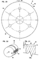
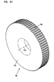
- FIGS. 20 and 21 One particular embodiment of an indenting or darting wheel 84 is shown at 160.
- the darting wheel 160 shown includes a plurality of indentation picks or teeth 162 extending radially from a surface 164 of the wheel 160.
- the darting wheel 84 rotates in a direction that is parallel to the flute direction. This means that the darting wheel 84 rotates in a plane that is generally transverse to the direction of the flutes.
- the teeth 162 are preferably uniformly spaced about the radial surface 164.
- the teeth 162 are spaced to correspond to the particular geometry of the corrugated sheet 66. That is, the spacing between adjacent ridges 80 of the corrugated sheet 66 is a primary factor in spacing between the adjacent teeth 162.
- the number of teeth 162 used is also a function of the diameter of the darting wheel 160.
- the darting wheel 160 includes at least 50, no greater than 200, and typically 100 - 150 teeth 162. In the specific example shown in FIG. 20 , there are 120 teeth 162.
- the darting wheel 160 has a diameter from the tip of one tooth 162 to another tooth 162 of at least 8 inches (20.3 cm), no greater than 12 inches (30.5 cm), typically 9 - 10 inches (22.9 - 25.4 cm), and in one example about 9.7 inches (24.6 cm).
- a diameter from the tip of one tooth 162 to another tooth 162 of at least 8 inches (20.3 cm), no greater than 12 inches (30.5 cm), typically 9 - 10 inches (22.9 - 25.4 cm), and in one example about 9.7 inches (24.6 cm).
- variation from this is possible.
- each of the teeth 162 has a crown 164 that is smooth and curved.
- the rounded shape to the crown 164 helps to deform the flutes 68 without tearing the corrugated sheet 66.
- the radius of the teeth 162 may often typically be at least 0.005 inch (0.01 cm), no greater than 2.0 inch (5.1 cm), typically 0.75 - 1.25 inch (1.9 - 3.2 cm), and preferably about 1.0 inch (2.54 cm).
- the thickness of each tooth is shown at dimension 168.
- the dimension 168 for the example shown, is at least 0.01 inch (0.03 cm), no greater than 0.05 inch (0.13 cm), and typically 0.02 - 0.04 inch (0.05 - 0.1 cm).
- the height of each tooth 162 is shown in FIG. 21 at dimension 170.
- the height 170 in some implementations, is at least 0.05 inch (0.13 cm), no greater than 0.5 inch (1.3 cm), and typically 0.1 - 0.3 inch (0.25 - 0.76 cm).
- Each tooth 162 has a pair of sides 171, 172, between which the crown 164 extends.
- the length of the tooth 162 between the sides 170, 171 is at least 0.2 inch (0.5 cm), no greater than 1 inch (2.54 cm), and typically 0.5 - 0.7 inch (1.3 - 1.8 cm).
- the darting wheel 160 is shown located between a pair of fluted rollers 176, 178.
- the fluted rollers 176, 178 are, in some instances, driven by the movement of the corrugated sheet 66 along the process 70.
- the fluted rollers 176, 178 help to keep the darting wheel 160 on-center with the flutes 68.
- the fluted rollers 176, 178 include flutes or corrugations 180 that will mesh with the corrugated sheet 66.
- FIG. 22 shows the rollers 176, 178 only partially corrugated. It should be understood that, in practice, the rollers 176, 178 are often fully corrugated.
- FIGS. 8 - 10 illustrate one of the flutes 68 after engaging the darting wheel 84, for example, the darting wheel 160.
- the ridge 80 forms inversion 110 to extend toward and to touch or engage the sealant bead 150. This helps to hold the inversion 110 and the double peak 116 in place for the folder wheel 86.
- the inversion 110 is shown in engagement with the sealant bead 150 but not in engagement with the non-corrugated sheet 64. In some implementations, the inversion 110 can be pushed fully through the sealant bead 150 into touching engagement with the non-corrugated sheet 64.
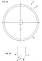
- Figs. 23 and 24 illustrate one example of folder wheel 86.
- the example of the folder wheel 86 in Figs. 14 and 15 is depicted at 185.
- the folder wheel 185 functions to press the flute double peak 116 against the non-corrugated media 64 and against the inversion 110 to form darted section 72.
- the folder wheel 86 rotates about a central axis 188 that is generally parallel to the direction of the flutes 68.
- the folding wheel 86 rotates in the same general plane as creaser wheel 88 (if used) and darting wheel 84; that is, folding wheel 86 rotates in a plane that is generally transverse to the direction of the flutes 68.
- the folder wheel 185 has a smooth, blunt surface 190 for engaging the corrugated sheet 66.
- the surface 190 in example embodiments, is a toroidal surface on a radius R of at least 1 inch (2.54 cm), no greater than 3 inches (7.6 cm), and typically 1.5 - 2.5 inches (3.8 - 6.4 cm).
- the folder wheel 185 has opposite axial surfaces 192, 194.
- the distance between the axial surfaces 192 and 194 generally defines the thickness of the folder wheel 185. In example embodiments, this thickness is at least 0.1 inch (0.25 cm), no greater than 0.5 inch (1.3 cm), and typically 0.2-0.4 inch (0.5 - 1.0 cm).
- the diameter of the example folder wheel 185 is at least 3 inches (7.6 cm), no greater than 10 inches (25.4 cm), and typically 5-7 inches (12.7 - 17.8 cm).
- each of the axial surfaces 192, 194 and the blunt surface 190 is curved, and in the illustrated embodiment, is on a radius r of at least 0.02 inch (0.05 cm), no greater than 0.25 inch (0.6 cm), and typically 0.08 - 0.15 inch (0.2 - 0.4 cm).
- Fig. 25 illustrates a perspective, schematic view of z-media 74 after being modified by indenting and folding to include the darted section 72, and after being separated into pieces 76, 77 by the cutter 90, Fig. 7 .
- the folded flutes 120 can be seen at the downstream edge 196.
- the air to be cleaned flows in at the upstream edge 198 as shown at arrows 199.
- the air flows through the Z-media 74 at the upstream edge 198, through the media, and then exits in the region 200 between the darted (folded) flutes 120 and the non-corrugated sheet 64.
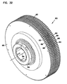
- Figs. 26 and 27 illustrate example filter elements utilizing Z-media 74 having folded flutes 120.
- the Z-media 74 with the folded flutes 120 is wound into filter element 202.
- the filter element 202 includes opposite flow faces 203, 204 that, in this instance, are parallel. In alternate configurations, one of the flow faces 203 or 204 may not lie in a single plane, e.g., it may be conical.
- An example of a conically shaped filter element with z-media is shown in U.S. Des. 399,944 ; U.S. Des. 428,128 ; and U.S. Des. 396,098 and z-media with folded flutes can be configured analogously.
- the flow face 203 is shown schematically, with only portions showing end flutes 205, but it should be understood that the entire filter face 203 will typically have end flutes 205.
- fluid to be filtered enters the upstream flow face (in this instance 204) and exits downstream flow face, in this instance, 203).
- the fluid generally flows in the same direction entering the upstream flow face 204 as it exits the downstream flow face 203. Again, this configuration generally referred to herein as a "straight through flow" filter.
- the particular filter element 202 is round, in that it has a circular cross-section.
- the filter element 202 may be modified by placing an appropriate gasket or other type of sealing members thereon.
- One example sealing gasket 208 is shown secured to an outer cylindrical surface 209 of the element 202.
- the sealing gasket 208 shown includes foamed polyurethane and forms a seal with a housing by compression of the gasket 208 against the housing.
- Examples of usable sealing gaskets include the ones described in U.S. patent number 6,190,432 and U.S. patent application serial number 09/875,844, filed June 6, 2001 , and commonly assigned hereto.
- Fig. 27 illustrates another example of a filter element 216 utilizing z-media 74 and wound into the filter element 216.
- the filter element 216 has opposite flow faces 217, 218 to accommodate straight through gas flow.
- this embodiment also shows the flow face 217 schematically, with only portions showing end flutes, but it should be understood that the entire filter face 217 typically will show the end flutes.
- the filter element 216 is obround. Specifically, this particular filter element 216 has a cross-section in the shape of two parallel sides 219, 220 joined at their ends by curved portions 221, 222.
- the filter element 216 may include appropriate sealing members or gaskets, and in the example shown, includes the type of sealing member 224 described in U.S. patent number 6,190,432 .
- This sealing member 224 includes polyurethane molded on a frame, secured to the element 216.
- a central core 226, 227 is shown as having the z-media 74 wound therearound.
- the filter elements 202, 216 can be coreless.
- coreless it is meant that the elements are absent a central mandrel, tube, stick, or other piece that the z-media 74 is wound around.
- the filter media described herein can be made into elements, of which examples are shown in Figs. 26 and 27 .
- the filter elements are useable in fluid (liquid or air) cleaners.
- One such system is depicted schematically in Fig. 27A generally at 230.
- equipment 232 such as a vehicle, having an engine 233, with some defined rated air flow demand, for example, at least 300 cfm, for example 500 - 1200 cfm, is shown schematically.
- Equipment 232 can include a bus, an over-the-highway truck, an off-road vehicle, a tractor, or marine equipment such as a powerboat.
- the engine 233 powers the equipment 232, through the use of an air and fuel mixture.
- the air flow is shown drawn into the engine 232 at an intake region 235.
- An optional turbo 236 is shown in phantom, as optionally boosting the air intake into the engine 233.
- An air cleaner 240 having a filter construction 242 is upstream of the engine 232 and the turbo 236. In general, in operation, air is drawn in at arrow 244 into the air cleaner 240 and through the primary element 242. There, particles and contaminants are removed from the air. The cleaned air flows downstream at arrow 246 into the intake 235. From there, the air flows into the engine 233 to power the equipment 232.
- useable systems include intake air filters gas turbine systems.
- the media can also be used in liquid (for example oil (lubrication), fuel or hydraulic) filters.
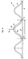
- a folding or darting step for a center darting of the type described above involves deformation or indentation (in a portion of a ridge 53) directed inwardly; i.e., from the outside surface 53a toward the inside surface 53b.
- a step in the folding process is providing a deformation (in the instance of Fig. 15 an indentation) in outside surface 53a, Fig. 6 , by directing a pin arrangement or similar construction against surface 53a in the general direction of arrow 55, Fig. 6 .
- This type of deformation step has generally been referred to as an "indentation step” or “darting step,” as explained above in connection with Fig. 7 and wheel or roller 84.
- containment and support can be provided by supporting the flute or corrugation (during deformation) from: (a) a location outside the corrugation (flute); (b) a location inside the corrugation (flute); or (c) both.
- the latter approach, in which the corrugation (flute) is supported on both the inside and the outside during the deformation process, will generally be referred to herein as an encapsulation approach, or by variants thereof.
- FIG. 28 an approach is shown in which the support is provided along a same side (outside) of a corrugation to be folded closed, as a side against which the indenter dart or indentation pin arrangement will press, with the support provided immediately adjacent opposite sides of the indentation pin arrangement.
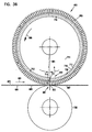
- Fig. 29 an approach is shown in which support is provided on a side (inside) of the corrugation opposite from that against which the indentation pin arrangement will press to start the deformation, again with support provided adjacent opposite sides of the indentation pin arrangement.
- Fig. 30 an encapsulation process is shown, in which support for the corrugation to be folded is provided both inside and outside of the corrugation, in each instance adjacent opposite sides of the indentation pin arrangement.
- the term "adjacent opposite sides of the indentation pin arrangement” and variants thereof, is meant to refer to the location of the support relative to where the indentation pin arrangement engages the corrugation to cause inversion.
- the term is meant to indicate that the support is located longitudinally, along the length of longitudinal extension of the corrugation, at least at the same longitudinal location as the location at which the indentation pin arrangement contacts the corrugation, except offset to the side of the corrugation location (typically ridge) where indentation contact occurs. This will sometimes be referenced as being indenting a corrugation that is supported at a region longitudinally adjacent where indentation will occur. This will be apparent from the detailed descriptions below. In Fig.
- reference numeral 370 generally indicates the fluted or corrugated media.
- the corrugated media 370 has a regular, curved, wave pattern for the corrugation 371, with straight flutes.
- a particular corrugation 371 to be folded is indicated.
- the initial folding step is conducted by a deformation or indentation pin arrangement (not shown) applied in the general direction of arrow 375 to an outside or convex side 376 (from the viewpoint of the arrow 375) to form an indent or deformation.
- the deformation pin is directed against the convex side (outside) 376 of the corrugation 371 in such a manner that: the corrugation 371 is first engaged by the pin arrangement at or along an apex 376a; and, such that the indentation force applied by the deformation pin arrangement is generally directed in a direction normal or orthogonal to a plane 377a defined by troughs 377 on opposite sides of apex 376a. It is noted, however, that variations from this, are possible.
- corrugation 371 is supported and contained, for the darting process, by form 380.
- the form 380 is depicted in phantom, in Fig. 28 .
- Form 380 is generally and preferably configured to have a corrugated portion 381 configured to have a surface 382 generally defined as an inverse of the convex or outside surface 371a (of corrugation 371).
- the form 380 is preferably configured to mate or mesh with the corrugations of the media. Although a perfect mesh or mate is not required, it will be preferred to have as much engagement as possible, to provide maximum support.
- the form 380 is preferably rigid, not flexible like the media of the corrugation 371.
- the form 380 for example, may comprise metal or a hard plastic.
- form 380 includes gap 383 therein, through which the darting or indentation pin arrangement can project, in the direction of arrow 375, to engage corrugation 371.
- gap 383 is positioned aligned with a portion of ridge 376a.
- corrugation support which occurs immediately on opposite sides of, or adjacent, the indentation pin, as characterized above, would be a specific form of indentation which occurs in a corrugation that is supported and contained for the darting process. In particular, it would be a form in which there is support on both "sides" of the indentation pin, as the indentation pin projects through a gap in the support.
- sides in the previous sentence meaning in the directions of double headed arrow 384, Fig. 28 , from gap 383.
- the flexible media 370 in the region of corrugation 371 is contained between points 388 and 390, against deformation either in the direction of arrow 391 or in the direction arrow 392.
- the support is provided, in part, at regions 395,396.
- a corrugation will be considered "supported and/or contained" by a support form 380, if either: (a) the form 380 contains the corrugation by contact with the corrugation at or near troughs 377 on opposite sides of the corrugation; or (b) the form 380 extends over the corrugation to cover a distance of the height (H1 of Fig. 6 ) of the corrugation which is at least 10% of the height (H1); or (c) both. Typically both are used and the extension will be at least 20% of the height (H1), preferably at least 30% of the height (H1), most preferably at least 90% (for example 100%) of the height (H1). That is, if surface 381 of form 380, Fig.
- the corrugation 28 extends from apex 376a downwardly toward plane 377a a distance of at least 10% of H1, the corrugation will be considered supported by the form 380. Again, typically the height or extent of support, in the direction of H1, will be at least 90% of H1, typically 100% of H1.
- Corrugated (fluted) sheet 400 comprises a regular, curved, wave pattern corrugation 401 of straight flutes.
- a particular corrugation or flute 405 is depicted, to be folded in a folding process initiated with an indentation pin arrangement directed toward convex (outside) surface 407, for example at apex 407a, under force in the general direction of arrow 408.
- the indentation pin arrangement is directed toward an apex 407a of the convex surface 407, in the direction of arrow 408 with force directed generally normal to, or orthogonal to, a plane 409 defined by troughs 410, on opposite sides of the corrugation 405. Variations from this, however, are possible.
- Corrugation 405 is shown supported inside (i.e. along a concave surface 411) by form 412.
- Form 412 includes a central recessed region 413 therein, to receive a depression or indent in corrugation 405 from the indentation pin arrangement.
- Form 412 also includes sides 414 and 415 generally defined to conform with a shape of corrugation 405 in regions 405a and 405b, respectively.
- the form or support 412 of Fig. 29 will generally keep the flexible media 400 centered with respect to an indentation pin arrangement directed thereagainst.
- the form 412 is preferably constructed from a rigid material.
- a corrugation will be considered supported along the inside as long as the support form along the inside extends, from plane 409 toward apex 407a, at least 10% of the peak height (H1 of Fig. 29 ).
- the inside support will extend at least 20%, preferably at least 30%, of H1.
- a typical example would be 40%-60% of H1.
- the form 412 As with the embodiment of Fig. 28 , for the form 412 to be considered to support the corrugation 405, it is not required that the form 412 have an outer surface along sides 414, 415, which has a shape in perfect match to the corrugation shape at these locations. However a configuration as close as possible to a matching shape, is preferred.
- the support in Fig. 29 is at least is at regions 416, 417, longitudinally adjacent where indentation will occur.
- Fig. 30 an extension of corrugated media 430 is depicted.
- the corrugated media 430 shown is generally a regular, curved, continuous wave pattern corrugation arrangement 431 with straight flutes.
- Corrugation 435 is shown positioned for a folding process to be initiated, by an indentation pin arrangement directed against convex surface 437 of corrugation 435 in the direction of arrow 438.
- corrugation 435 is shown encapsulated, between outside or outer form 440, shown in phantom, supporting outside 435a, which generally corresponds to form 380, Fig.
- corrugation 435 which is contained along both the convex (outside) and the concave (inside) surfaces, in the vicinity of the indentation pin (preferably on opposite sides of the indentation pin arrangement or darting pin at the same longitudinal location along the length of the corrugation 435) during indentation pin arrangement (or darting pin) projection into the media.
- the corrugation 435 will remain centered and will not undesirably move during the initiation of the folding process.
- the length D2 ( Fig. 6 ) of the corrugation is approximately 1.2-1.4 times D1
- the indentation pin arrangement a single indentation or darting pin directed against the apex of the corrugation, with the pin being on the order of 0.7 - 0.8 mm thick, and on the order of 5 mm to 40 mm wide.
- the length D2 is greater than about 1.4 times D1
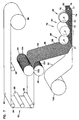
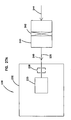
- a corrugating station is shown at 500, with two corrugated rollers 501, 502 positioned to form a corrugating bite 503 therebetween.
- a non-corrugated media sheet 506 is shown directed into the bite 503 to be corrugated with a resulting continuous corrugated web 507 having corrugations 508 thereacross in a direction generally perpendicular to the machine direction 509 being shown.
- a non-corrugated sheet 515 is shown being brought into engagement with side 516 of corrugated sheet 507.
- the two sheets 507, 515 will be tacked to one another at various points there along, to facilitate the manufacturing process.
- an adhesive typically a hot melt, can be used. In some instances sonic welding can be used to effect the tacking.
- an adhesive bead, hot melt, or sealant strip 525 is positioned between the two sheets 507, 515, in a central location.
- the sealant of the sealant strip is used to ensure a seal, at the location of the fold, in the final product.
- other sealing techniques such as sonic welds may be useable.
- the sealant strip 525 can be applied to continuous sheet 506, before it is corrugated on side 516. If it is applied to continuous sheet 506, before it is corrugated, in general the relevant surface portion of one of the corrugating rollers 501, 502 would preferably have a gap therein to accommodate the sealant bead. In the instance of Fig. 31 , the gap (not viewable) would be in roller 502.
- sealant bead will follow the corrugations 508 in the corrugated material.
- the sealant will be more appropriately located inside of the folds or creases, after processing. This means that a relatively secure closed fold will result, with less sealant used, than would typically be required for an approach in which sealant is first applied to the non-corrugated sheet, for example as shown optionally at 525a, before the non-corrugated sheet and the corrugated sheet are brought together.
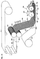
- a deformation (or indentation or darting) pin arrangement in this instance comprising a wheel 531, is directed into the convex side of each corrugation 508 on side 507a of corrugated sheet 507.
- an upper form 540 for supporting (outside support) of each corrugation during the indentation process is provided. Support to the webs 507 and 515 underneath, is provided by rollers 541, 542.
- media web next proceeds to a pressing/folding station 550, at which sides resulting from the initial indentation process are folded over toward one another, to form the four crease fold shown in Fig. 15 .
- a press is used (to cause a center folded strip section 570), which will make a press strip that is at least 1 mm wide, typically 4 mm to 40 mm wide in the resulting media construction 571.
- the pressing station 550 can comprise a wheel 572, with a cross-section generally analogous to that shown for wheel 185, Figs. 23 and 24 , except dimensioned in width to cause a press width as indicated above.
- the media 571 is shown slit down strip 570. This will result in two extensions 581, 582 of media 583, each of which has an end respectively terminating in folds, for each convex flute (relative to the flat sheet) with ends similar to end or fold arrangement 118, Fig. 15 .
- folded flutes could be made at an edge (for example one or more of edges 595, 596), instead of along a center portion of the corrugated media, using a similar approach. In this latter instance, no final step of slitting would necessarily be required, unless trimming was considered preferable to remove excess sealant or media.
- the initial indentation pressure may be applied asymmetrically to the corrugation, i.e., not directed against an apex to cause a symmetrical fold.
- a support arrangement which utilizes a rotating roller or wheel.
- the roller or wheel is indicated generally at reference numeral 650, in perspective view.
- the roller wheel 650 is shown in side elevational view.
- a portion of roller or wheel 650 is shown in enlarged view.
- Fig. 35 is a fragmented, schematic, cross-section of roller or wheel 650, taken generally along line 35-35, Fig. 34 .
- Fig. 36 a schematic view showing an indentation step, using an indentation pin arrangement 652 is shown.
- Fig. 36a an enlarged portion of Fig. 36 is depicted.
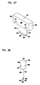
- Figs. 37 and 38 a darting or indentation pin projection is shown.
- Figs. 39 - 40 an internal cam component is shown.
- wheel 650 is an outside support wheel 655 for corrugations, during an indentation step of a corrugation folding process.
- wheel 650 includes a projectable/retractable indentation pin arrangement 652, not viewable in Fig. 32 , to provide for an initial indentation step into a corrugation, during a portion of a folding process. This will be discussed below, in connection with the descriptions of Figs. 36 and 36a .
- the wheel 650 includes an outer, annular, corrugation engagement surface 657, depicted enlarged in Fig. 34 .
- the outer corrugation engagement surface 657 comprises a plurality of alternating ridges 658 and troughs 659 sized and configured, to engage an outside surface of a corrugated material.
- the ridges 658 and troughs 659 are configured to define a regular, curved, wave pattern of straight ridges and troughs, corresponding to the corrugation pattern of the media to be folded, except surface 657 is positioned around the outside of a wheel 650, and thus the corrugations 658 and troughs 659 have a slight radius to their extension, not present in the corrugated media when the media is flattened out, as shown in Fig. 31 .
- a bottom 661 of each trough 659 includes, in a central portion 662 thereof, a slot 663.
- the slot 663 is sized and positioned so that an indentation pin arrangement 652, not shown in Fig. 32 , can selectively be projected through the slot 663, in a direction away from a center axis 664 of the wheel 650 (or toward media), to cause an indentation in a selected, supported, corrugation during use. (Also the indentation pin arrangement 652 can be retracted through slot 663 toward axis 664.)
- the wheel 650 is mounted on a rotation bearing 665.
- the wheel 650 is mounted such that its rotation will be driven by the corrugated media in use. That is, preferably wheel 650 is not driven during use, except through engagement with the corrugated media to be folded, Fig. 31 .
- each ridge 658 and trough 659 has an end extension 668, 669 at opposite ends of each slot 663 of sufficient length, to support the corrugation to be deformed at opposite ends of the slot 663, during an indentation process.
- the length of each extension 668, 669 is at least 6 mm., and typically at least 12 mm.
- each slot 663 will have a length of at least 6 mm., typically at least 12 mm.; and a width of at least 0.5 mm., typically at least 0.7 mm.
- the indentation pin arrangement 652 will include a pin projection/retraction mechanism constructed and arranged to selectively drive or project an indentation or darting pin arrangements through one of slots 663 against or into an engaged corrugation to be folded, and to selectively retract an indentation pin arrangement when appropriate. This process can be understood, by consideration of the embodiment depicted in Figs. 36-40 .
- wheel 650 is shown schematically, in engagement with corrugated media 672.
- corrugation 673 is shown supported by trough 674 of wheel 650; see fragmentary enlargement Fig. 36A .
- Trough 674 is a particular one of the troughs 659 and thus includes a slot corresponding to slot 663, Fig. 32 , in a central portion thereof.
- indentation pin arrangement 677 is shown driven through slot 678 in a radially outward direction from surface 657, and axis 664 ( Fig. 36 ), into supported corrugation 673.
- an indentation corresponding to the indentation shown in Fig. 9 in cross-section, is initiated.
- the indentation is shown to be sufficiently long (or deep) to cause the indent 679 to connect the non-corrugated sheet 680. While this is preferred, it is not required in all applications.
- the indentation pin arrangement 652, including indentation pin 677, is preferably arranged such that projection of the pin 677 outwardly through slot 663, Fig. 36A , is: (a) at its maximum extent of projection at indentation formation position 681; i.e., when the pin 677 is approximately orthogonal to a plane defined by sheet 680 or as generally defined by troughs 682, 683 on opposite sides of the corrugation 673; and (b) so that the pin 677 is completely retracted out of engagement with the corrugation 673 when the media is not supported, for example at a rotation angle A ( Fig.
- upstream direction is meant to a direction from which the web 684 is fed into the roller 650.
- the web generally moves in the direction of arrow 685.
- the upstream side is indicated at 686 and the downstream side is indicated at 687, for the web 684.
- the rotation angle A would be defined as an angle extending clockwise from the center line or indentation formation position 681. It is noted that for the arrangement shown in Fig. 36 , during operation roller 650 would rotate counterclockwise, i.e. in the general direction of arrow 688. Of course the process could be configured for a reverse rotation and machine direction.
- the pin arrangement 652 ( Fig. 36A ) be under projection movement radially outwardly when it engages the apex of an engaged corrugation plane. This is facilitated by relatively small angle A, since a small angle A helps to provide that the pin is actually being forced radially outwardly from axis 664, toward and into engagement with the corrugation 673, while the corrugation 673 is supported. This is shown at locations 681 and 681 a, in Fig. 36A .
- a variety of arrangements can be used to project and retract the indentation pin 677.
- a particular pin projection/retraction arrangement 690 is depicted in Figs. 35-40 . It uses a plurality of spring loaded pins 677, one associated with each slot 663. Referring to Figs. 37 and 38 a pin 677 is shown in its entirety.
- the pin 677 includes a projection portion 692, which is configured to pass through slot 674 with tip 693 directed toward a corrugation, in use.
- the projection portion 692 ( Fig. 37 ) includes beveled ends 694, 695, for a preferred indentation or deformation.
- Edge 696 ( Fig. 38 ) can be rounded or beveled, to facilitate indentation without damage to the media.
- the tip 693 is mounted on projection support 697, in extension outward from base 698.
- the base 698 extends between end portions 699, 700, with each end 699, 700 including a spring receiving trough 701 therein.
- Base 698 includes, opposite projection support 697, a surface 703 for use, as described below.
- FIG. 35 a schematic depiction, an individual pin 677 is shown mounted by first and second circular springs 705, 706, to be biased in the direction of arrow 707 within wheel 650.
- each pin 677 will rotate with wheel 650 around bearing 665, Fig. 32 , in line with (and in coordination with) its associated slot 663.
- the wheel 650 is mounted to rotate around a stationary, circular cam 711, Fig. 35 .
- stationary in this context, it is meant that the cam 711 does not rotate with wheel 650 in use.
- outer annular surface 712 of cam 711 includes a portion 712 which extends (counterclockwise in Fig. 39 ) between points 713 and 714 of circular, stationary, cam 711 and is appropriately recessed, relative to the wheel 650, such that pins 677 passing there over, are completely retracted.
- surface portion 716 in extension counterclockwise between points 717 and 718 operates as a cam surface which, when engaged by surface 703 of each pin 677, will force the pin 677 to project outwardly through slot 663, an appropriate extent to cause desired indentation, usually an extent of projection on the order of 50% - 100% of the flute height.
- cam ramp 720 is preferably configured to cause an amount of projection of an associated pin outwardly of at least 50% - 100% of the flute height over a preferred rotation angle (angle A) as previously described for 36. The reason for this is that it causes a substantial projection effect of the pin, against an associated corrugation in a web, during indenting or darting while the corrugation is supported.
- Cam ramp 721 allows for pin retraction.
- a smooth roller 725 for back up support to pressure exerted n web 684 by roller 650, is shown.
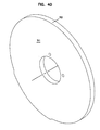
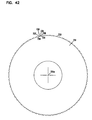
- FIG. 41 an inside support 730 is depicted.
- Inside support 730 generally comprises a rotatable roller or wheel 731 (or receiver roller or wheel), mounted to rotate around axis 731a, on a bearing, not shown.
- the wheel 731 has an outer annular surface 732 configured to provide support to the inside of a corrugation, during an indentation process.
- Wheel 731 shown in Fig. 42 .
- Surface 732 can be viewed to comprise a series of troughs 734, configured to receive media troughs (or inverted ridges) on opposite sides of a corrugation ridge to be indented. Between each pair of troughs 734 is provided an indentation support 736 which preferably comprises opposite, radially outwardly projecting side projections 737, 738 and a recessed center 739.
- a portion of wheel 731 is depicted in enlarged view, in Fig. 43 .
- the term "recessed" when used in connection with defining center 739, is meant to indicate that a bottom 739a of the recessed center 739 is preferably recessed in the direction of, but not necessarily as far as, bottoms 734a of the troughs 734.
- each center 739 is recessed the same amount of the troughs 734.
- each recessed center 739 has a bottom 739a which, in the cross-section shown in Fig. 43 , has a radius about the same as the media thickness plus 0.5x the indention pin thickness.
- troughs 734 and sides 737, 738 are selected to correspond with corrugated media to be supported, during an indentation process.
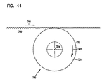
- Partially recessed center 739 is generally sized to receive a projecting portion of an indentation pin arrangement, and a corresponding inverted or indented tip of corrugation media, during an indentation process. An example of this is shown in Figs. 44 and 45 .
- the recess center 739 should be sized to allow for room of the thickness of the media (twice) and the thickness of the indenting pin, during an indentation or deformation process. In this manner, the media will not likely be torn or substantially damaged, during the inside support deformation or indentation process.
- wheel 731 Fig. 44
- wheel 731 would be mounted on a bearing, in a typical process, to be rotated or driven by the corrugated media 740 as opposed to being independently driven. This will help ensure that the engaged and supported corrugations in the media are centrally positioned.
- the direction of movement of the media 740 is indicated at arrow 741, and the direction of rotation of wheel 731 by arrow 742.
- web 740 is shown being indented at 752, with inside support provided by roller 731.
- the web direction is indicated at arrow 741.
- the direction of indentation is shown at arrows 754.
- indentation pin used with an inside support analogous to inside support 730 may be positioned on a wheel analogous to wheel 650, Fig. 32 , if desired.
- the process would be an encapsulation process for the corrugated media 750, to be indented.
- midweb darting was involved.
- the indentation could be caused by an arrangement analogous to the wheel 650, Fig. 32 . That is, with outside support and an underneath support roller that does not include corrugated support structure.
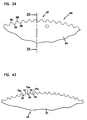
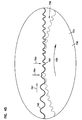
- FIG. 47 an extension of web 760 is depicted.
- Web 760 has a center 801 and opposite edges 802, 803.
- the web 750 generally comprises a corrugated sheet 810 attached to a non-corrugated sheet 811.
- a corrugation process along the center 801 can be conducted as shown in Fig. 36 .
- a corrugation process along either one of edges 802, 803, can be also conducted with a process analogous to that shown in Fig. 36 , without inside support, as long as the indentation is directed against a ridge of the corrugated media 810, in the direction toward the non-corrugated media 811.
- Sealant could be prepositioned at along the edge, between the corrugated and non-corrugated media sheets 810, 811, to facilitate the process.
- sonic welding could alternatively to used, in some systems.
- Fig. 47 indentation at edge 802 is shown.
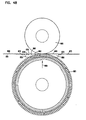
- Fig. 48 it may be desirable to cause the indentation to be driven against a corrugation in an opposite direction from the non-corrugated media.
- Fig. 48 a web corrugated media 850 secured to non-corrugated media 851 is shown.
- the non-corrugated media 856 is shown folded away from surface 860 of the corrugated media. This exposes surface 860 to potential engagement for corrugation.
- An encapsulated process such as shown in Fig.
- Fig. 32 can be used to create a dart fold in each of the upwardly directed ridges of the media.
- An approach in accord with Fig. 48 can be used to create a dart or fold in each of the downwardly directed ridges in the same media. This can be used to create a media then which has each of the inlet flutes each folded closed at the downstream edge; and, each of the outlet flutes folded closed at the upstream edge.
- indentation arrangements are depicted utilizing preferred roller configurations.
- continuous belts can be configured to provide the support, if desired; and, they can be provided with appropriate slots therein, for indentation pin arrangements to project therethrough.
- roller configurations depicted which would typically use rollers on the order of about 150 mm to 300 mm in diameter for the indentation roller ( Fig. 32 ) and about 150 mm to 300 mm in diameter for the receiver roller ( Fig. 41 ), are convenient to manufacture and use.
- a follow-up step of folding media points 900, 901, Fig. 36a over, typically toward one another, to create the fold of Fig. 15 would be required. This can be conducted with roller 572, Fig. 31 .
- the roller 572 would preferably be as described above.
- fluted filter media construction is meant to refer to a filter construction which includes the media, whether the construction is the media itself or the media provided in the form of an overall serviceable filter element or cartridge, for example cartridges as shown in Figs. 26 and 27 .
- the fluted filter media construction preferably comprises a corrugated sheet of filter media having a curved wave pattern of corrugations, preferably a regular curved wave pattern of straight corrugations as defined.
- the corrugations are such that a set of them define individuals flutes each having an end closure defined by regular fold arrangement in corresponding ones of the set of corrugations.
- the regular fold arrangement of each corrugation includes at least two folds. Typically for the preferred arrangements described, such as shown in Fig. 15 , four folds are provided at each corrugation which is folded closed. For these, two of the folds are generally upper, inwardly directed folds and two of the folds are generally lower, outwardly directed folds.
- the typical fluted filter media construction will comprise a sheet of corrugated media having individual flutes each closed by a regular fold arrangement, secured to a non-corrugated sheet of filter media.
- the filter media construction will include such a combination of a corrugated sheet and a non-corrugated sheet configured to provide a filter cartridge having a set of inlet flutes and a set of outlet flutes, the inlet flutes each being closed to passage of unfiltered fluid therethrough, adjacent the outlet face and each outlet flute being closed, to passage of unfiltered fluid therein, adjacent the inlet face.
- adjacent in this context, is meant to refer to a closure that occurs within a distance 20% of the total length of the flute of the most adjacent face.
- the closure is within 10% of the length of the flute, of the most adjacent face.
- the closure of at least one of the sets of inlet flute and outlet flutes is by the regular fold pattern. In some instances both are closed by the regular fold pattern.
- a corrugation or flute end is not closed by a fold, it may be closed by a barrier such as a sealant barrier, or in some other manner.
- a filter cartridge will contain a set of flutes folded closed at one face, and another set of flutes closed by a sealant barrier at another face.
- the corrugated sheet and the non-corrugated sheet can be jointly coiled to form a coiled media construction.
- the coiled media construction may be circular, or may be obround, for example race track shape. In other arrangements, the media would be used in the form of a stack of strips.
- the regular fold arrangement would include some sealant herein, to facilitate and maintain closure.
- a process for manufacturing a filter media construction including a sheet of fluted (typically corrugated) filter media having curved wave pattern of corrugations is provided.
- the process generally includes steps of: (1) deforming a portion of a flute or corrugation to define at least one foldable tip; and (2) folding the at least one foldable tip over, to fold the flute or corrugation closed.
- two foldable tips in each corrugation are generated, and are folded over, preferably toward one another.
- the process is conducted on a sheet of corrugated media having a curved wave pattern of corrugations.
- the sheet of corrugated filter media is secured to a sheet of non-corrugated media, to form a continuous web, prior to the step of indenting and folding.
- the process may be conducted as a mid-web deformation and folding process, with follow-up slitting. It also may be conducted along a web edge. When conducted along an edge, it can be conducted in a direction toward the uncorrugated media, or, by folding the non-corrugated media out of the way, it can be conducted in a direction away from the non-corrugated media. Of course the process can be conducted on corrugated media that is not secured to non-corrugated media.
- the deformation process can be conducted without support, or with outside support or inside support (or both) provided to a corrugation at a location longitudinally adjacent the location or deformation.
- longitudinally adjacent in this context, it is meant that the support occurs in the same location as the deformation, except moved out of the way of the deformation pin arrangement which causes the deformation.
- the deformation (typically a step of indenting) can be conducted with an indenting wheel, with a step of folding comprising pressing with a folding wheel.
- the indenting wheel may comprise a wheel having an outer corrugated surface, to provide for outside corrugation support, with at least one, and typically a plurality, of spaced indentation pins.
- the indentation pins may be mounted with a projection/retraction arrangement that allows the pins to be projected outwardly from the indenting wheel when indentation is to be conducted, and to be retracted out of the way, when desired.
- the corrugated sheet or web would be formed by passing a non-corrugated sheet into the bite between corrugation rollers.
- sealant may be provided on the corrugated sheet prior to deformation, by providing the sealant on the web when it is passed into the corrugating rollers, to form the corrugated sheet. This can be advantageous for reasons previously discussed.
Landscapes
- Chemical & Material Sciences (AREA)
- Chemical Kinetics & Catalysis (AREA)
- Filtering Materials (AREA)
- Filtering Of Dispersed Particles In Gases (AREA)
- Absorbent Articles And Supports Therefor (AREA)
Claims (18)
- Verfahren zum Herstellen einer Filtermedienkonstruktion, die eine Schicht aus gerilltem Filtermedium mit einem welligen Wellenmuster aus Rillen umfasst; wobei das Verfahren die folgenden Schritte umfasst:(a) Verformen eines Teils einer Rille zum Definieren mindestens einer faltbaren Spitze; und(b) Umschlagen der mindestens einen faltbaren Spitze, um die Rille durch Falten zu verschließen; wobei die geschlossene Rille mit einem Dichtungsmittel versiegelt wird.
- Verfahren nach Anspruch 1, bei dem:(a) die Rille, welche bei dem Verformungsschritt verformt wird, Teil eines gleichmäßigen, welligen Wellenmusters aus Rillen ist.
- Verfahren nach einem der Ansprüche 1 oder 2, bei dem:(a) die Schicht aus gerilltem Filtermedium vor dem Schritt des Verformens an einer Schicht aus nicht gerilltem Filtermedium befestigt wird, um eine Endlosbahn zu bilden.
- Verfahren nach einem der Ansprüche 1-3, bei dem:(a) der Schritt des Verformens ein mittig der Bahn ausgeführter Umstülpungsprozess ist und auf Rillenkämmen durchgeführt wird, die von der Schicht aus nicht gewelltem Filtermedium weg zeigen;(b) der Schritt des Umschlagens ein Umschlagen mittig der Bahn umfasst, bei dem die mindestens eine faltbare Spitze zu der Schicht aus nicht gerilltem Filtermedium umgeschlagen wird, um eine mittige Umschlagslinine zu formen; und(c) das Verfahren einen Schritt des Teilens der Bahn entlang der mittigen Umschlagslinine umfasst.
- Verfahren nach einem der Ansprüche 1-4, bei dem:(a) der Schritt des Verformens ein zentrales Umstülpen umfasst, um zwei faltbare Spitzen zu erzeugen; und,(b) der Schritt des Faltens einen Schritt umfasst, bei dem die zwei faltbaren Spitzen zueinander umgeschlagen werden.
- Verfahren nach einem der Ansprüche 1-5, bei dem:(a) der Schritt des Verformens ein Umstülpen mit einer Riffelwalze umfasst; und(b) der Schritt des Umschlagens ein Pressen mit einem Faltrad umfasst.
- Verfahren nach einem der Ansprüche 1-6, bei dem:(a) der Schritt des Verformens ein Umstülpen einer ausgewählten Rille umfasst, die an einer Stelle in Längsrichtung neben der Stelle, an der Verformung auftreten wird, durch eine Abstützung gestützt wird, welche mindestens eine von:(i) einer äußeren Rillenabstützung; und(ii) einer inneren Rillenabstützung umfasst.
- Verfahren nach einem der Ansprüche 1-7, bei dem:(a) der Schritt des Verformens mit einer Riffelwalze durchgeführt wird, welche umfasst:(i) eine äußere gerillte Fläche, ausgestaltet um während des Umstülpens eine äußere Rillenabstützung zur Verfügung zu stellen; und(ii) eine Vorschub-/Rückzug-Kerbstiftanordnung.
- Verfahren nach einem der Ansprüche 1-8 mit den Schritten:(a) Formen des gerillten Mediums, indem eine nicht gerillte Bahn durch einen Zwischenraum zwischen einem Paar von Riffelwalzen geführt wird; und(b) Auftragen von Dichtungsmittel auf das gerillte Medium, indem das Dichtungsmittel aufgetragen wird, bevor das Medium gewellt ist.
- Rillenfilterkonstruktion hergestellt gemäß dem Verfahren nach einem der Ansprüche 1-9, umfassend:(a) eine gerillte Schicht aus Filtermedium, welche ein welliges Wellenmuster aus Rillen umfasst;(i) wobei ein Satz der Rillen einzelne Rinnen definiert, die jeweils einen Endverschluss besitzen, der durch eine gleichmäßige Faltenanordnung in einer entsprechenden Rille definiert ist;(A) wobei der Endverschluss gegen den Durchgang eines Fluids versiegelt verschlossen ist.
- Rillenfilterkonstruktion nach Anspruch 10, bei der:(a) die gerillte Schicht aus Filtermedium ein gleichmäßiges, welliges Wellenmuster aus geraden Rillen umfasst.
- Rillenfilterkonstruktion nach einem der Ansprüche 10 oder 11, umfassend:(a) eine nicht gerillte Schicht aus Filtermedium, welche an der gerillten Schicht aus Filtermedium befestigt ist.
- Rillenfilterkonstruktion nach Anspruch 12, bei der:(a) die Rillen ein Rinnen/Ebenen-Verhältnis im Bereich von einschließlich 1.2 - 2,0 besitzen.
- Rillenfilterkonstruktion nach Anspruch 12, bei der:(a) die gerillte Schicht und die nicht gerillte Schicht in einem Filter angeordnet sind, so dass ein Satz von Eintrittsrinnen und ein Satz von Austrittsrinnen definiert wird, die sich zwischen einer Eintrittsfläche und einer Austrittsfläche erstrecken:(i) wobei jede Eintrittsrinne benachbart zur Austrittsfläche für den Durchgang von ungefiltertem Fluid dort hindurch geschlossen ist; und(ii) jede Austrittsrinne benachbart zur Eintrittsfläche für den Durchgang von ungefiltertem Fluid dort hindurch geschlossen ist.
- Rillenfilterkonstruktion nach Anspruch 14, bei der:(a) jede Eintrittsrinne durch die gleichmäßige Faltenanordnung benachbart zur Austrittsfläche geschlossen ist.
- Rillenfilterkonstruktion nach einem der Ansprüche 14 oder 15, bei der:(a) jede Austrittsrinne durch die gleichmäßige Faltenanordnung benachbart zur Eintrittsfläche geschlossen ist.
- Rillenfilterkonstruktion nach einem der Ansprüche 14-16, bei der:(a) jede gleichmäßige Faltenanordnung ein Dichtungsmittel darin umfasst.
- Rillenfilterkonstruktion nach einem der Ansprüche 12-14, bei der:(a) die gerillte Schicht und die nicht gerillte Schicht gemeinsam zu einer gewickelten Filtermediumstruktur gewickelt sind.
Applications Claiming Priority (3)
| Application Number | Priority Date | Filing Date | Title |
|---|---|---|---|
| US39500902P | 2002-07-10 | 2002-07-10 | |
| US395009P | 2002-07-10 | ||
| PCT/US2003/002799 WO2004007054A1 (en) | 2002-07-10 | 2003-01-31 | Fluted filter medium and process for its manufacture |
Publications (2)
| Publication Number | Publication Date |
|---|---|
| EP1521627A1 EP1521627A1 (de) | 2005-04-13 |
| EP1521627B1 true EP1521627B1 (de) | 2011-02-16 |
Family
ID=29584655
Family Applications (1)
| Application Number | Title | Priority Date | Filing Date |
|---|---|---|---|
| EP03764291A Revoked EP1521627B1 (de) | 2002-07-10 | 2003-01-31 | Gefaltetes filtermaterial und verfahren zu dessen herstellung |
Country Status (12)
| Country | Link |
|---|---|
| US (2) | US7997425B2 (de) |
| EP (1) | EP1521627B1 (de) |
| JP (2) | JP4638226B2 (de) |
| KR (1) | KR101009857B1 (de) |
| CN (2) | CN100379483C (de) |
| AT (1) | ATE498447T1 (de) |
| AU (1) | AU2003216131B2 (de) |
| CA (1) | CA2491926A1 (de) |
| DE (2) | DE60336060D1 (de) |
| MX (1) | MXPA05000459A (de) |
| WO (1) | WO2004007054A1 (de) |
| ZA (1) | ZA200500192B (de) |
Families Citing this family (129)
| Publication number | Priority date | Publication date | Assignee | Title |
|---|---|---|---|---|
| WO1997040918A1 (en) * | 1996-04-26 | 1997-11-06 | Donaldson Company, Inc. | Fluted filter media |
| MXPA05006084A (es) | 2002-12-11 | 2005-09-30 | Donaldson Co Inc | Medio filtrante con forma de z con sistemas de limpieza de flujo inverso y metodos. |
| KR20050098922A (ko) | 2003-02-11 | 2005-10-12 | 도널드선 컴파니 인코포레이티드 | 에어 크리너 배열과 서비스가능한 필터 구성 요소 및 방법 |
| WO2004082795A2 (en) | 2003-03-18 | 2004-09-30 | Donaldson Company, Inc. | Improved process and materials for coiling z-filter media, and/or closing flutes of filter media; and, products |
| US7704292B2 (en) * | 2003-12-17 | 2010-04-27 | Ruihua Hu | Fluid filter |
| EP2865437B1 (de) | 2003-12-22 | 2020-12-09 | Donaldson Company, Inc. | Filterelement mit einer Dichtungsanordnung |
| US20090266041A1 (en) * | 2003-12-22 | 2009-10-29 | Donaldson Company, Inc. | Seal arrangement for filter element; Filter element assembly; and, methods |
| DE602005022836D1 (de) | 2004-02-17 | 2010-09-23 | Donaldson Co Inc | Luftreinigeranordnungen, wartungsfähige filterelemente und verfahren |
| MXPA06012575A (es) | 2004-04-30 | 2006-12-15 | Donaldson Co Inc | Arreglos de filtro, alojamientos, montajes y metodos. |
| US7905936B2 (en) | 2004-04-30 | 2011-03-15 | Donaldson Company, Inc. | Filter arrangements; housing; assemblies; and, methods |
| DE102004023107A1 (de) * | 2004-05-11 | 2005-12-08 | Mann + Hummel Gmbh | Kompaktes Filterelement |
| US7967886B2 (en) | 2004-06-08 | 2011-06-28 | Donaldson Company, Inc. | Z-filter media pack arrangement; and, methods |
| EP2243536B1 (de) | 2004-06-14 | 2013-11-20 | Donaldson Company, Inc. | Luftfilteranordnung und kartusche |
| DE602005019417D1 (de) | 2004-07-20 | 2010-04-01 | Donaldson Co Inc | Z-filtermedienpackungsanordnung, filterpatrone, luftreinigungsvorrichtungsanordnung und verfahren |
| EP1778384B2 (de) | 2004-08-06 | 2017-10-11 | Donaldson Company, Inc. | Luftfilteranordnung |
| US7931725B2 (en) | 2004-11-02 | 2011-04-26 | Baldwin Filters, Inc. | Fluted filter apparatus |
| US20110197556A1 (en) | 2004-11-02 | 2011-08-18 | Baldwin Filters, Inc. | Filter element |
| US20070186528A1 (en) * | 2006-02-15 | 2007-08-16 | Baldwin Filters, Inc. | Fluted filter apparatus |
| US20060091064A1 (en) * | 2004-11-02 | 2006-05-04 | Baldwin Filters, Inc. | Filter apparatus with separable seal support frame |
| US7318851B2 (en) | 2004-11-02 | 2008-01-15 | Baldwin Filters, Inc. | Filter element |
| US20060091061A1 (en) * | 2004-11-02 | 2006-05-04 | Baldwin Filters, Inc. | Filter assembly with sealing system |
| US7909954B2 (en) * | 2004-11-03 | 2011-03-22 | Baldwin Filters, Inc. | Method and apparatus for winding a filter media pack |
| US7569090B2 (en) | 2004-11-12 | 2009-08-04 | Donaldson Company, Inc. | Method of forming filter arrangements; and, apparatus |
| CN102512889B (zh) | 2005-01-13 | 2015-11-25 | 唐纳森公司 | 空气过滤器滤筒和空气滤清器组件 |
| US7520913B2 (en) | 2005-02-04 | 2009-04-21 | Donaldson Company, Inc. | Non-cylindrical filter elements, and methods |
| WO2007035802A1 (en) * | 2005-09-20 | 2007-03-29 | Honeywell International Inc. | Filter and method of making |
| KR101463630B1 (ko) | 2005-10-11 | 2014-11-19 | 도날드슨 컴파니, 인코포레이티드 | 에어 필터 배열, 조립체, 및 방법 |
| CN102302880A (zh) | 2005-11-09 | 2012-01-04 | 唐纳森公司 | 过滤元件的密封结构;过滤元件组件和方法 |
| DE202005019910U1 (de) * | 2005-12-19 | 2007-04-19 | Mann + Hummel Gmbh | Filter |
| DE202005019909U1 (de) * | 2005-12-19 | 2007-04-26 | Mann + Hummel Gmbh | Gewickelter Filterkörper |
| US7708797B2 (en) | 2006-01-20 | 2010-05-04 | Donaldson Company, Inc. | Air cleaner configured for receipt of various sized filter cartridges; components thereof; and, methods |
| US7753982B2 (en) | 2006-02-17 | 2010-07-13 | Baldwin Filters, Inc. | Filter with drained jacket, seal indicator/lock means, and seal baffle |
| US7625419B2 (en) | 2006-05-10 | 2009-12-01 | Donaldson Company, Inc. | Air filter arrangement; assembly; and, methods |
| EP2043758B1 (de) | 2006-06-22 | 2016-11-30 | Donaldson Company, Inc. | Luftreinigeranordnung und Luftfilterpatrone |
| US7713321B2 (en) | 2006-06-22 | 2010-05-11 | Donaldson Company, Inc. | Air cleaner arrangements; components thereof; and, methods |
| US10040020B2 (en) * | 2006-12-06 | 2018-08-07 | Baldwin Filters, Inc. | Fluid filter apparatus having filter media wound about a winding frame |
| US9757676B2 (en) | 2006-12-06 | 2017-09-12 | Baldwin Filters, Inc. | Method and apparatus for winding a filter element |
| CN102743937B (zh) | 2007-02-02 | 2015-09-16 | 唐纳森公司 | 空气过滤介质包、过滤元件、空气过滤介质及方法 |
| AU2008268271B8 (en) | 2007-06-26 | 2014-04-10 | Donaldson Company, Inc. | Filtration media pack, filter elements, and methods |
| US8728193B2 (en) | 2007-09-07 | 2014-05-20 | Donaldson Company, Inc. | Air filter assembly; components thereof and methods |
| US9545593B2 (en) * | 2007-11-01 | 2017-01-17 | Baldwin Filters, Inc. | Winding core pressure relief for fluted filter |
| RU2010124005A (ru) | 2007-11-15 | 2011-12-20 | Дональдсон Компани, Инк. (Us) | Патрон воздушного фильтра (варианты), способ его формирования и узел воздухоочистителя |
| US8491689B2 (en) * | 2007-12-21 | 2013-07-23 | 3M Innovative Properties Company | Joined filter media pleat packs |
| WO2009100067A1 (en) * | 2008-02-04 | 2009-08-13 | Donaldson Company, Inc. | Method and apparatus for forming fluted filtration media |
| MX2010009305A (es) | 2008-02-25 | 2010-09-24 | Donaldson Co Inc | Elemento filtrante para limpieza por pulsaciones y metodos. |
| US9283503B2 (en) | 2008-04-04 | 2016-03-15 | Donaldson Company, Inc. | Filter element, dust collector, and methods |
| US7959703B2 (en) * | 2008-06-30 | 2011-06-14 | Baldwin Filters, Inc. | Fluted filter with integrated frame |
| US8048187B2 (en) * | 2008-06-30 | 2011-11-01 | Baldwin Filters, Inc. | Filter frame attachment and fluted filter having same |
| BRPI0916516B1 (pt) | 2008-07-22 | 2021-05-04 | Donaldson Company, Inc | Cartucho de filtro de ar e conjunto de filtro de ar |
| USD646369S1 (en) | 2008-07-22 | 2011-10-04 | Donaldson Company, Inc. | Filter cartridge |
| BRPI0915931B1 (pt) * | 2008-07-25 | 2020-03-31 | Donaldson Company, Inc. | Pacotes de agentes de filtração pregueados |
| JP5607624B2 (ja) * | 2008-08-06 | 2014-10-15 | ドナルドソン カンパニー,インコーポレイティド | 対面濾材シートの片側に縦溝流路付き濾材シートが積層された片側積層物及びそれを形成するための方法、並びに、フィルタエレメント |
| US8317890B2 (en) | 2008-08-29 | 2012-11-27 | Donaldson Company, Inc. | Filter assembly; components therefor; and, methods |
| US7918996B1 (en) * | 2008-09-08 | 2011-04-05 | De Bruijn Hans | Stormwater filter bag |
| US8961637B2 (en) | 2009-01-14 | 2015-02-24 | Donaldson Company, Inc. | Filter element; components thereof; and methods |
| WO2010099317A2 (en) | 2009-02-27 | 2010-09-02 | Donaldson Company, Inc. | Filter cartridge; components thereof; and methods |
| KR101124524B1 (ko) * | 2009-03-26 | 2012-03-15 | 양순영 | 필터 제조장치 및 그 제조방법 |
| BRPI1014857B1 (pt) | 2009-03-31 | 2020-09-15 | Donaldson Company, Inc | Cartucho de filtro de ar, limpador de ar e método de manutenção do mesmo |
| CN102481501B (zh) * | 2009-08-03 | 2016-10-12 | 唐纳森公司 | 用于形成具有楔形槽的槽式过滤介质的方法和装置 |
| ES2437165T3 (es) | 2009-10-02 | 2014-01-09 | Donaldson Company, Inc. | Cartucho de filtro con tablero central, recolectores de polvo, y métodos |
| CN102574043B (zh) | 2009-10-14 | 2015-04-29 | 唐纳森公司 | 具有密封件的过滤器滤芯及方法 |
| EP3415218B1 (de) * | 2010-01-25 | 2021-05-05 | Donaldson Company, Inc. | Gefaltete filtriermedien mit konischen rillen |
| WO2011115973A2 (en) | 2010-03-17 | 2011-09-22 | Baldwin Filters, Inc. | Fluid filter |
| WO2011115979A2 (en) | 2010-03-17 | 2011-09-22 | Baldwin Filters, Inc. | Fluid filter |
| WO2011130853A1 (en) | 2010-04-20 | 2011-10-27 | Fibracast Ltd. | Formed sheet membrane element and filtration system |
| JP5890683B2 (ja) * | 2011-01-28 | 2016-03-22 | キヤノン株式会社 | 情報処理装置およびその方法 |
| US11235274B2 (en) | 2011-06-30 | 2022-02-01 | Donaldson Company, Inc. | Filter systems; components; features; and, methods of assembly and use |
| KR101972618B1 (ko) | 2011-06-30 | 2019-08-16 | 도날드슨 컴파니, 인코포레이티드 | 공기/오일 분리기 조립체; 컴포넌트 및 방법 |
| WO2013056373A1 (en) | 2011-10-20 | 2013-04-25 | Fibracast Ltd. | Coating device and process for coating formed sheet membrane element |
| US9387425B2 (en) | 2011-10-26 | 2016-07-12 | Donaldson Company, Inc. | Filter assemblies; components and features thereof; and, methods of use and assembly |
| KR101325819B1 (ko) * | 2012-01-10 | 2013-11-05 | 재단법인한국조선해양기자재연구원 | 선박용 해수 스트레이너 |
| US9371777B2 (en) | 2012-01-23 | 2016-06-21 | Bha Altair, Llc | Filter assembly including pleat tip shapes |
| BR112015001748B1 (pt) | 2012-07-25 | 2022-03-15 | Baldwin Filters, Inc | Conjunto de filtro |
| US9114342B2 (en) * | 2012-12-05 | 2015-08-25 | Rps Products, Inc. | Filter with covered edges |
| US9269998B2 (en) | 2013-03-13 | 2016-02-23 | Fluidic, Inc. | Concave gas vent for electrochemical cell |
| RU2670852C9 (ru) * | 2013-05-22 | 2018-11-30 | Дональдсон Компани, Инк. | Вертикальная система впуска воздуха, воздухоочиститель и фильтрующий элемент |
| CN105555389B (zh) | 2013-06-28 | 2017-10-31 | 唐纳森公司 | 用于空气滤清器组件的过滤器滤芯 |
| EP3021952B1 (de) | 2013-07-19 | 2020-10-21 | Donaldson Company, Inc. | Filterelement und luftreiniger |
| DE102013019327B4 (de) * | 2013-11-20 | 2023-06-01 | Mann+Hummel Gmbh | Filterelement mit Filterbalg und Verwendung des Filterelements |
| CN106068154B (zh) * | 2014-01-07 | 2018-12-25 | 唐纳森公司 | 过滤介质包、过滤器元件以及过滤介质 |
| CN103994500A (zh) * | 2014-05-15 | 2014-08-20 | 牛京伟 | 分体式空气净化器及其过滤模块 |
| EP3194048B1 (de) | 2014-09-15 | 2020-07-08 | Donaldson Company, Inc. | Filterpatrone und luftreinigeranordnung |
| US9752541B2 (en) * | 2014-12-05 | 2017-09-05 | Caterpillar Inc. | Filter media |
| US10532310B2 (en) | 2014-12-27 | 2020-01-14 | Donaldson Company, Inc. | Filter cartridges; air cleaner assemblies; housings; features; components; and, methods |
| RU2709693C2 (ru) | 2015-03-02 | 2019-12-19 | Дональдсон Компани, Инк. | Картридж фильтра для воздуха и воздухоочистительный узел |
| TWI534006B (zh) * | 2015-04-09 | 2016-05-21 | Filter element and its forming method | |
| US11278833B2 (en) | 2015-08-17 | 2022-03-22 | Parker-Hamilton Corporation | Filter media packs, methods of making, and ultrasonic cutting or welding |
| EP3337588B8 (de) | 2015-08-17 | 2020-11-11 | Parker-Hannificn Corporation | Verfahren zur herstellung von filtermedienpaketen |
| US10479046B2 (en) * | 2015-08-19 | 2019-11-19 | Imagine Tf, Llc | Absorbent microstructure arrays and methods of use |
| USD786935S1 (en) | 2015-11-20 | 2017-05-16 | Baldwin Filters, Inc. | Filter element |
| JP6911029B2 (ja) | 2015-12-18 | 2021-07-28 | ドナルドソン カンパニー,インコーポレイティド | フィルタカートリッジおよび空気清浄装置アセンブリ |
| RU2741961C2 (ru) | 2016-02-12 | 2021-02-01 | Дональдсон Компани, Инк. | Фильтрующие элементы, воздухоочистительные узлы и способы применения и сборки |
| US10682597B2 (en) | 2016-04-14 | 2020-06-16 | Baldwin Filters, Inc. | Filter system |
| EP3471856B1 (de) | 2016-06-17 | 2022-07-27 | Donaldson Company, Inc. | Lutreinigeranordnung und filtereinsatz |
| EP3481530B1 (de) | 2016-07-06 | 2021-08-25 | Donaldson Company, Inc. | Luftreinigeranordnungen |
| BR112018074575B1 (pt) | 2016-07-22 | 2023-01-17 | Nantenergy, Inc | Célula eletroquímica |
| AU2017298994B2 (en) | 2016-07-22 | 2019-09-12 | Nantenergy, Inc. | Moisture and carbon dioxide management system in electrochemical cells |
| CN115569464B (zh) | 2016-11-04 | 2025-06-27 | 唐纳森公司 | 过滤元件、空气滤清器组件、以及使用和组装的方法 |
| EP3548160B1 (de) | 2016-12-01 | 2021-10-06 | Donaldson Company, Inc. | Filterelemente, luftreinigeranordnung und verfahren zur verwendung und anordnung |
| CA3049263C (en) * | 2017-02-16 | 2025-05-06 | Clarcor Inc | FILTER MEDIUM PACKETS, MANUFACTURING PROCESSES, AND ULTRASONIC CUTTING OR WELDING |
| CN107119489B (zh) * | 2017-05-09 | 2019-11-08 | 广州市友安消防科技有限公司 | 一种过滤元件及其制备方法 |
| PT3631115T (pt) | 2017-05-24 | 2022-09-20 | Saint Gobain Placo | Elemento de construção corrugado, aparelho para produzir tal elemento e método de fabrico |
| MX2019014474A (es) | 2017-06-05 | 2020-09-07 | Donaldson Co Inc | Conjuntos de filtro de aire de carga lateral y metodos de uso. |
| CN107419580A (zh) * | 2017-06-20 | 2017-12-01 | 郭鹏 | 叠盘多辊滤液机 |
| RU2769798C2 (ru) | 2017-08-09 | 2022-04-06 | Дональдсон Компани, Инк. | Картриджи воздушного фильтра |
| PL3675983T3 (pl) | 2017-08-31 | 2023-09-04 | Donaldson Company, Inc. | Wkłady filtrów; zespoły filtra powietrza |
| MX2020005265A (es) | 2017-11-27 | 2020-08-24 | Donaldson Co Inc | Conjuntos de filtro de aire y metodos de uso. |
| EP4516379A1 (de) | 2018-01-24 | 2025-03-05 | Donaldson Company, Inc. | Filterelement, systeme und verfahren |
| US11865489B2 (en) | 2018-04-09 | 2024-01-09 | Donaldson Company, Inc. | Filter element with fluted filter media |
| USD905842S1 (en) | 2018-06-15 | 2020-12-22 | Donaldson Company, Inc. | Filter cartridge |
| EP3815172A4 (de) | 2018-06-29 | 2022-03-09 | Form Energy, Inc. | Rollmembrandichtung |
| CN112805868A (zh) | 2018-06-29 | 2021-05-14 | 福恩能源公司 | 金属空气电化学电池构架 |
| EP3643390A1 (de) * | 2018-10-25 | 2020-04-29 | Carl Freudenberg KG | Filter mit separatorblechen mit spezieller faltung |
| CN109750558A (zh) * | 2019-01-25 | 2019-05-14 | 莆田盾之星滤清器有限公司 | 一种双层复合滤清器滤纸及其制作方法 |
| CN113692312B (zh) | 2019-02-04 | 2023-05-26 | 唐纳森公司 | 用于对流体进行过滤的过滤器元件 |
| USD1002792S1 (en) | 2019-02-05 | 2023-10-24 | Donaldson Company, Inc. | Filter cartridge |
| US12083464B2 (en) | 2019-02-08 | 2024-09-10 | Donaldson Company, Inc. | Filter element, air cleaner assembly, and methods |
| US11118545B2 (en) | 2019-03-26 | 2021-09-14 | Caterpillar Inc. | Precleaner system |
| EP3991234A4 (de) | 2019-06-28 | 2024-01-17 | Form Energy, Inc. | Gerätearchitekturen für metall-luft-batterien |
| EP3881922B1 (de) | 2020-03-19 | 2024-03-13 | Donaldson Company, Inc. | Filterelement mit dichtungsaufnahme |
| EP4147296A4 (de) | 2020-05-06 | 2025-08-13 | Form Energy Inc | Elektrochemisches energiespeichersystem mit entkoppelter elektrode |
| CN111888857B (zh) * | 2020-08-19 | 2025-04-04 | 陕西秦科世博航空科技有限公司 | 一种高效空气滤芯及一种快速拆卸的高效空气过滤器 |
| US11666844B2 (en) | 2020-09-30 | 2023-06-06 | Caterpillar Inc. | Filtration device having a latch mechanism adapter |
| CN118660742A (zh) | 2022-01-18 | 2024-09-17 | 唐纳森公司 | 过滤器滤筒、空气净化器组件、壳体、特征、部件、以及方法 |
| CN115366484B (zh) * | 2022-09-06 | 2025-06-17 | 山西奇色环保科技股份有限公司 | 一种滤芯加工生产线 |
| WO2024155734A1 (en) | 2023-01-17 | 2024-07-25 | Donaldson Company, Inc. | Filter cartridge |
| WO2025240907A1 (en) | 2024-05-17 | 2025-11-20 | Donaldson Company, Inc. | Filter elements and assemblies |
| WO2025240912A1 (en) | 2024-05-17 | 2025-11-20 | Donaldson Company, Inc. | Filter elements and assemblies |
| US12434181B1 (en) | 2024-11-01 | 2025-10-07 | Donaldson Company, Inc. | Air cleaner and filtration assemblies |
Family Cites Families (81)
| Publication number | Priority date | Publication date | Assignee | Title |
|---|---|---|---|---|
| US399944A (en) * | 1889-03-19 | Lantern-frame | ||
| US428128A (en) * | 1890-05-20 | Cloth-piling machine | ||
| US396098A (en) * | 1889-01-15 | Combined strawberry-vine cutter and cultivator | ||
| US398046A (en) * | 1889-02-19 | Garment fastener and support | ||
| US891428A (en) * | 1907-04-11 | 1908-06-23 | William H Latus | Process of applying surface paper to corrugated packing-boards. |
| US1729135A (en) * | 1925-12-23 | 1929-09-24 | Harold W Slauson | Air and oil filter |
| US2038071A (en) * | 1932-11-09 | 1936-04-21 | Patent Finance Corp | Fluid treating device |
| US2019186A (en) * | 1933-03-01 | 1935-10-29 | H S Kaiser Company | Air filter |
| US2190886A (en) * | 1939-06-07 | 1940-02-20 | Air Mase Corp | Filter means and method of making same |
| US2397759A (en) * | 1942-04-17 | 1946-04-02 | Sigmund Miroslav | Filter |
| US2599604A (en) * | 1949-07-13 | 1952-06-10 | Jordan V Bauer | Filter element |
| GB703823A (en) | 1952-04-18 | 1954-02-10 | Jordan Victor Bauer | Filter element |
| BE561979A (de) | 1956-11-10 | |||
| US3025963A (en) * | 1958-03-13 | 1962-03-20 | Russell H Curtis | Products useful as filtering devices and methods of making them |
| US3112184A (en) * | 1958-09-08 | 1963-11-26 | Corning Glass Works | Method of making ceramic articles |
| US3025964A (en) * | 1958-09-29 | 1962-03-20 | Mine Safety Appliances Co | Zigzag filter element and method of making it |
| US3020977A (en) * | 1959-08-19 | 1962-02-13 | Simpson Herbert Corp | Filter device |
| US3037637A (en) * | 1960-04-26 | 1962-06-05 | Mine Safety Appliances Co | Spiral roll filter unit |
| US3070937A (en) * | 1960-05-05 | 1963-01-01 | Mine Safety Appliances Co | Mist removing device |
| US3112262A (en) * | 1960-07-12 | 1963-11-26 | New York Business Dev Corp | Filter unit and filter cartridge therefor |
| US3076554A (en) * | 1960-08-03 | 1963-02-05 | Mine Safety Appliances Co | Filter coil |
| US3323963A (en) * | 1964-01-08 | 1967-06-06 | Mine Safety Appliances Co | Method of making filter coil |
| US3346121A (en) * | 1965-08-13 | 1967-10-10 | Corning Glass Works | Filter and method for its production |
| US3401803A (en) * | 1965-12-06 | 1968-09-17 | Mine Safety Appliances Co | Filter formed from corrugated and flat sheets |
| US3372533A (en) * | 1966-07-11 | 1968-03-12 | Farr Co | Self-supporting high density filter |
| GB1213219A (en) | 1968-06-19 | 1970-11-25 | Mine Safety Appliances Co | Filter formed from corrugated and flat sheets |
| US3640396A (en) | 1970-04-03 | 1972-02-08 | Fram Corp | Filter |
| US3859068A (en) | 1972-05-09 | 1975-01-07 | Tenneco Inc | Pleated air filter |
| US4039457A (en) * | 1973-02-02 | 1977-08-02 | Robert Bosch G.M.B.H. | Coiled filter element for filtering of liquids |
| US4181513A (en) * | 1974-11-05 | 1980-01-01 | Toyobo Co., Ltd. | Carbon adsorptive filter material with layers of reinforcing non woven fabrics needle punched |
| SE409948B (sv) | 1976-03-16 | 1979-09-17 | Nederman Bill P Ph | Filteranordning for avskiljning av fasta partiklar ur gaser, speciellt svetsgaser |
| JPS56133005A (en) * | 1980-03-19 | 1981-10-17 | Nippon Soken Inc | Filter element for liquid |
| JPS57113822A (en) * | 1980-12-30 | 1982-07-15 | Nippon Soken Inc | Fine particle collecting filter |
| US4430223A (en) * | 1981-02-25 | 1984-02-07 | Nippondenso Co., Ltd. | Filter element for filtering fluid and method of producing same |
| JPS57156015A (en) * | 1981-03-22 | 1982-09-27 | Nippon Soken Inc | Radial flow type collecting filter for fine particle |
| EP0068662B1 (de) * | 1981-06-23 | 1987-01-07 | Nippondenso Co., Ltd. | Filterelement |
| US4460388A (en) * | 1981-07-17 | 1984-07-17 | Nippon Soken, Inc. | Total heat exchanger |
| US4410427A (en) * | 1981-11-02 | 1983-10-18 | Donaldson Company, Inc. | Fluid filtering device |
| AU540009B2 (en) | 1982-02-16 | 1984-10-25 | Matsushita Electric Industrial Co., Ltd. | Exhaust gas filter |
| US4512891A (en) | 1982-11-16 | 1985-04-23 | Donaldson Company, Inc. | Pleated filter element with controlled expansibility and frame therefor |
| DE3501182C2 (de) * | 1985-01-16 | 1987-03-19 | Daimler-Benz Ag, 7000 Stuttgart | Abgasfilter für Dieselmotoren |
| DE3542963A1 (de) * | 1985-12-05 | 1987-06-11 | Kernforschungsz Karlsruhe | Filterpack |
| JPH0616808B2 (ja) | 1987-08-05 | 1994-03-09 | 進和テック株式会社 | バグ再生式集塵装置 |
| JPH01171615A (ja) | 1987-12-25 | 1989-07-06 | Toyo Roki Seizo Kk | フィルタエレメント |
| JPH01207112A (ja) | 1988-02-12 | 1989-08-21 | Toyo Roki Seizo Kk | フィルタエレメントの製造方法 |
| US5174895A (en) * | 1988-03-16 | 1992-12-29 | Mordeki Drori | Coiled filter strip with upstream and downstream butt ends |
| US5015379A (en) * | 1988-03-16 | 1991-05-14 | Mordeki Drori | Coiled filter strip with upstream and downstream butt ends |
| US4925561A (en) * | 1988-03-31 | 1990-05-15 | Tsuchiya Mfg. Co., Ltd. | Composite planar and triangularly pleated filter element |
| JP2830080B2 (ja) * | 1988-07-08 | 1998-12-02 | 株式会社デンソー | ▲ろ▼過エレメントおよびその製造方法 |
| JPH0225009A (ja) | 1988-07-14 | 1990-01-26 | Toshiba Corp | 箔巻変圧器 |
| JP2619062B2 (ja) | 1989-03-15 | 1997-06-11 | 株式会社東芝 | 電極基板及び液晶表示装置の製造方法 |
| JPH037911U (de) * | 1989-06-12 | 1991-01-25 | ||
| EP0412931A1 (de) * | 1989-08-08 | 1991-02-13 | Alusuisse-Lonza Services Ag | Verfahren zur Herstellung eines keramischen Schaumkörpers |
| EP0412930A1 (de) * | 1989-08-08 | 1991-02-13 | Alusuisse-Lonza Services Ag | Verfahren zur Herstellung eines keramischen Schaumkörpers |
| JPH03111581U (de) * | 1990-02-23 | 1991-11-14 | ||
| JP3118646B2 (ja) | 1991-03-29 | 2000-12-18 | 日本無機株式会社 | ジグザグ状エアフィルタ濾材の製造方法 |
| JP3000750B2 (ja) * | 1991-09-20 | 2000-01-17 | 株式会社デンソー | 自己発熱型フィルタ |
| JPH05306614A (ja) * | 1992-04-28 | 1993-11-19 | Matsushita Electric Ind Co Ltd | 排気ガスフィルタとその製造方法 |
| JP3239517B2 (ja) * | 1992-06-17 | 2001-12-17 | 株式会社デンソー | 濾過エレメントの製造方法 |
| DE4234930A1 (de) * | 1992-10-16 | 1994-04-21 | Schwaebische Huettenwerke Gmbh | Filter zum Abscheiden von Verunreinigungen aus Abgasen |
| JP3331722B2 (ja) * | 1993-04-05 | 2002-10-07 | 株式会社デンソー | フィルタ |
| JP3362453B2 (ja) * | 1993-05-21 | 2003-01-07 | 株式会社デンソー | 濾過エレメント |
| US5435958A (en) * | 1993-08-02 | 1995-07-25 | Munters Corporation | Method for making a humidity exchanger medium |
| JPH09267015A (ja) * | 1996-03-29 | 1997-10-14 | Osaka Gas Co Ltd | 活性炭素繊維を用いたフィルタ− |
| US5902364A (en) * | 1996-04-26 | 1999-05-11 | Donaldson Company, Inc. | Conical filter |
| US5792247A (en) * | 1996-04-26 | 1998-08-11 | Donaldson Company, Inc. | Integrated resonator and filter apparatus |
| WO1997040918A1 (en) * | 1996-04-26 | 1997-11-06 | Donaldson Company, Inc. | Fluted filter media |
| US5820646A (en) * | 1996-04-26 | 1998-10-13 | Donaldson Company, Inc. | Inline filter apparatus |
| USD398046S (en) | 1996-04-26 | 1998-09-08 | Donaldson Company, Inc. | Combined filter element and frame therefor |
| USD399944S (en) | 1996-04-26 | 1998-10-20 | Donaldson Company, Inc. | Conical filter |
| US5895574A (en) * | 1996-04-26 | 1999-04-20 | Donaldson Company, Inc. | Rolled liquid filter using fluted media |
| US5772883A (en) * | 1996-04-26 | 1998-06-30 | Donaldson Company, Inc. | Slanted inline filter |
| JP4300612B2 (ja) | 1999-01-21 | 2009-07-22 | 日東紡績株式会社 | ガラス繊維用サイズ剤 |
| US6190432B1 (en) * | 1999-02-26 | 2001-02-20 | Donaldson Company, Inc. | Filter arrangement; sealing system; and methods |
| US6210469B1 (en) * | 1999-02-26 | 2001-04-03 | Donaldson Company, Inc. | Air filter arrangement having first and second filter media dividing a housing and methods |
| US6235195B1 (en) * | 1999-02-26 | 2001-05-22 | Donaldson Company, Inc. | Filter element incorporating a handle member |
| US6179890B1 (en) * | 1999-02-26 | 2001-01-30 | Donaldson Company, Inc. | Air cleaner having sealing arrangement between media arrangement and housing |
| US6416605B1 (en) * | 1999-11-24 | 2002-07-09 | Donaldson Company, Inc. | Method for manufacturing fluted media |
| JP2001310402A (ja) | 2000-04-27 | 2001-11-06 | Rengo Co Ltd | 段ボールシートの製造方法 |
| US6610126B2 (en) * | 2001-06-06 | 2003-08-26 | Donaldson Company, Inc. | Filter element having sealing members and methods |
| US6887343B2 (en) * | 2002-12-20 | 2005-05-03 | Fleetguard, Inc. | Filter coating, winding, finishing and manufacturing system |
-
2003
- 2003-01-31 US US10/520,544 patent/US7997425B2/en not_active Expired - Fee Related
- 2003-01-31 DE DE60336060T patent/DE60336060D1/de not_active Expired - Lifetime
- 2003-01-31 CN CNB038210258A patent/CN100379483C/zh not_active Expired - Fee Related
- 2003-01-31 AU AU2003216131A patent/AU2003216131B2/en not_active Ceased
- 2003-01-31 CA CA002491926A patent/CA2491926A1/en not_active Abandoned
- 2003-01-31 AT AT03764291T patent/ATE498447T1/de not_active IP Right Cessation
- 2003-01-31 JP JP2004521419A patent/JP4638226B2/ja not_active Expired - Fee Related
- 2003-01-31 KR KR1020057000455A patent/KR101009857B1/ko not_active Expired - Fee Related
- 2003-01-31 CN CN2008100081696A patent/CN101306277B/zh not_active Expired - Fee Related
- 2003-01-31 EP EP03764291A patent/EP1521627B1/de not_active Revoked
- 2003-01-31 MX MXPA05000459A patent/MXPA05000459A/es unknown
- 2003-01-31 WO PCT/US2003/002799 patent/WO2004007054A1/en not_active Ceased
- 2003-07-08 DE DE20310495U patent/DE20310495U1/de not_active Expired - Lifetime
-
2005
- 2005-01-10 ZA ZA200500192A patent/ZA200500192B/xx unknown
- 2005-04-05 JP JP2005001943U patent/JP3111581U/ja not_active Expired - Lifetime
-
2011
- 2011-08-11 US US13/207,978 patent/US8512499B2/en not_active Expired - Fee Related
Also Published As
| Publication number | Publication date |
|---|---|
| JP4638226B2 (ja) | 2011-02-23 |
| DE20310495U1 (de) | 2003-11-13 |
| WO2004007054A1 (en) | 2004-01-22 |
| US7997425B2 (en) | 2011-08-16 |
| MXPA05000459A (es) | 2005-03-23 |
| CN100379483C (zh) | 2008-04-09 |
| CN101306277B (zh) | 2011-11-02 |
| JP3111581U (ja) | 2005-07-28 |
| ZA200500192B (en) | 2007-03-28 |
| US8512499B2 (en) | 2013-08-20 |
| US20110297611A1 (en) | 2011-12-08 |
| AU2003216131A1 (en) | 2004-02-02 |
| CN101306277A (zh) | 2008-11-19 |
| JP2005532163A (ja) | 2005-10-27 |
| DE60336060D1 (de) | 2011-03-31 |
| ATE498447T1 (de) | 2011-03-15 |
| AU2003216131A2 (en) | 2004-02-02 |
| US20060163150A1 (en) | 2006-07-27 |
| CA2491926A1 (en) | 2004-01-22 |
| KR101009857B1 (ko) | 2011-01-19 |
| EP1521627A1 (de) | 2005-04-13 |
| KR20050023407A (ko) | 2005-03-09 |
| AU2003216131B2 (en) | 2009-04-23 |
| CN1678383A (zh) | 2005-10-05 |
Similar Documents
| Publication | Publication Date | Title |
|---|---|---|
| EP1521627B1 (de) | Gefaltetes filtermaterial und verfahren zu dessen herstellung | |
| US11007468B2 (en) | Method of forming filter arrangements; and, apparatus | |
| EP1768761B1 (de) | Z-filtermedienpackungsanordnung | |
| EP1608453B1 (de) | Verbessertes verfahren zum wickeln von z-filtermedien | |
| EP1781397B1 (de) | Luftreinigungsvorrichtungsanordnungen und verfahren | |
| WO2006014941A2 (en) | Z-filter media pack arrangement; and, methods | |
| EP1771237A1 (de) | Luftfilteranordnung, anordnung und verfahren |
Legal Events
| Date | Code | Title | Description |
|---|---|---|---|
| PUAI | Public reference made under article 153(3) epc to a published international application that has entered the european phase |
Free format text: ORIGINAL CODE: 0009012 |
|
| 17P | Request for examination filed |
Effective date: 20050210 |
|
| AK | Designated contracting states |
Kind code of ref document: A1 Designated state(s): AT BE BG CH CY CZ DE DK EE ES FI FR GB GR HU IE IT LI LU MC NL PT SE SI SK TR |
|
| AX | Request for extension of the european patent |
Extension state: AL LT LV MK RO |
|
| DAX | Request for extension of the european patent (deleted) | ||
| 17Q | First examination report despatched |
Effective date: 20070827 |
|
| GRAP | Despatch of communication of intention to grant a patent |
Free format text: ORIGINAL CODE: EPIDOSNIGR1 |
|
| GRAS | Grant fee paid |
Free format text: ORIGINAL CODE: EPIDOSNIGR3 |
|
| GRAA | (expected) grant |
Free format text: ORIGINAL CODE: 0009210 |
|
| AK | Designated contracting states |
Kind code of ref document: B1 Designated state(s): AT BE BG CH CY CZ DE DK EE ES FI FR GB GR HU IE IT LI LU MC NL PT SE SI SK TR |
|
| REG | Reference to a national code |
Ref country code: GB Ref legal event code: FG4D |
|
| REG | Reference to a national code |
Ref country code: CH Ref legal event code: EP |
|
| REG | Reference to a national code |
Ref country code: IE Ref legal event code: FG4D |
|
| REF | Corresponds to: |
Ref document number: 60336060 Country of ref document: DE Date of ref document: 20110331 Kind code of ref document: P |
|
| REG | Reference to a national code |
Ref country code: DE Ref legal event code: R096 Ref document number: 60336060 Country of ref document: DE Effective date: 20110331 |
|
| REG | Reference to a national code |
Ref country code: NL Ref legal event code: VDEP Effective date: 20110216 |
|
| PG25 | Lapsed in a contracting state [announced via postgrant information from national office to epo] |
Ref country code: SE Free format text: LAPSE BECAUSE OF FAILURE TO SUBMIT A TRANSLATION OF THE DESCRIPTION OR TO PAY THE FEE WITHIN THE PRESCRIBED TIME-LIMIT Effective date: 20110216 Ref country code: PT Free format text: LAPSE BECAUSE OF FAILURE TO SUBMIT A TRANSLATION OF THE DESCRIPTION OR TO PAY THE FEE WITHIN THE PRESCRIBED TIME-LIMIT Effective date: 20110616 Ref country code: ES Free format text: LAPSE BECAUSE OF FAILURE TO SUBMIT A TRANSLATION OF THE DESCRIPTION OR TO PAY THE FEE WITHIN THE PRESCRIBED TIME-LIMIT Effective date: 20110527 Ref country code: GR Free format text: LAPSE BECAUSE OF FAILURE TO SUBMIT A TRANSLATION OF THE DESCRIPTION OR TO PAY THE FEE WITHIN THE PRESCRIBED TIME-LIMIT Effective date: 20110517 |
|
| PG25 | Lapsed in a contracting state [announced via postgrant information from national office to epo] |
Ref country code: SI Free format text: LAPSE BECAUSE OF FAILURE TO SUBMIT A TRANSLATION OF THE DESCRIPTION OR TO PAY THE FEE WITHIN THE PRESCRIBED TIME-LIMIT Effective date: 20110216 Ref country code: NL Free format text: LAPSE BECAUSE OF FAILURE TO SUBMIT A TRANSLATION OF THE DESCRIPTION OR TO PAY THE FEE WITHIN THE PRESCRIBED TIME-LIMIT Effective date: 20110216 Ref country code: AT Free format text: LAPSE BECAUSE OF FAILURE TO SUBMIT A TRANSLATION OF THE DESCRIPTION OR TO PAY THE FEE WITHIN THE PRESCRIBED TIME-LIMIT Effective date: 20110216 Ref country code: BE Free format text: LAPSE BECAUSE OF FAILURE TO SUBMIT A TRANSLATION OF THE DESCRIPTION OR TO PAY THE FEE WITHIN THE PRESCRIBED TIME-LIMIT Effective date: 20110216 Ref country code: BG Free format text: LAPSE BECAUSE OF FAILURE TO SUBMIT A TRANSLATION OF THE DESCRIPTION OR TO PAY THE FEE WITHIN THE PRESCRIBED TIME-LIMIT Effective date: 20110516 Ref country code: FI Free format text: LAPSE BECAUSE OF FAILURE TO SUBMIT A TRANSLATION OF THE DESCRIPTION OR TO PAY THE FEE WITHIN THE PRESCRIBED TIME-LIMIT Effective date: 20110216 Ref country code: CY Free format text: LAPSE BECAUSE OF FAILURE TO SUBMIT A TRANSLATION OF THE DESCRIPTION OR TO PAY THE FEE WITHIN THE PRESCRIBED TIME-LIMIT Effective date: 20110216 |
|
| PG25 | Lapsed in a contracting state [announced via postgrant information from national office to epo] |
Ref country code: EE Free format text: LAPSE BECAUSE OF FAILURE TO SUBMIT A TRANSLATION OF THE DESCRIPTION OR TO PAY THE FEE WITHIN THE PRESCRIBED TIME-LIMIT Effective date: 20110216 Ref country code: DK Free format text: LAPSE BECAUSE OF FAILURE TO SUBMIT A TRANSLATION OF THE DESCRIPTION OR TO PAY THE FEE WITHIN THE PRESCRIBED TIME-LIMIT Effective date: 20110216 |
|
| PLBI | Opposition filed |
Free format text: ORIGINAL CODE: 0009260 |
|
| PG25 | Lapsed in a contracting state [announced via postgrant information from national office to epo] |
Ref country code: SK Free format text: LAPSE BECAUSE OF FAILURE TO SUBMIT A TRANSLATION OF THE DESCRIPTION OR TO PAY THE FEE WITHIN THE PRESCRIBED TIME-LIMIT Effective date: 20110216 Ref country code: CZ Free format text: LAPSE BECAUSE OF FAILURE TO SUBMIT A TRANSLATION OF THE DESCRIPTION OR TO PAY THE FEE WITHIN THE PRESCRIBED TIME-LIMIT Effective date: 20110216 |
|
| PLAX | Notice of opposition and request to file observation + time limit sent |
Free format text: ORIGINAL CODE: EPIDOSNOBS2 |
|
| 26 | Opposition filed |
Opponent name: MANN + HUMMEL GMBH Effective date: 20111116 |
|
| REG | Reference to a national code |
Ref country code: DE Ref legal event code: R026 Ref document number: 60336060 Country of ref document: DE Effective date: 20111116 |
|
| PLAF | Information modified related to communication of a notice of opposition and request to file observations + time limit |
Free format text: ORIGINAL CODE: EPIDOSCOBS2 |
|
| PGFP | Annual fee paid to national office [announced via postgrant information from national office to epo] |
Ref country code: IT Payment date: 20120130 Year of fee payment: 10 |
|
| PLBB | Reply of patent proprietor to notice(s) of opposition received |
Free format text: ORIGINAL CODE: EPIDOSNOBS3 |
|
| PG25 | Lapsed in a contracting state [announced via postgrant information from national office to epo] |
Ref country code: MC Free format text: LAPSE BECAUSE OF NON-PAYMENT OF DUE FEES Effective date: 20120131 |
|
| REG | Reference to a national code |
Ref country code: CH Ref legal event code: PL |
|
| REG | Reference to a national code |
Ref country code: IE Ref legal event code: MM4A |
|
| PG25 | Lapsed in a contracting state [announced via postgrant information from national office to epo] |
Ref country code: CH Free format text: LAPSE BECAUSE OF NON-PAYMENT OF DUE FEES Effective date: 20120131 Ref country code: LI Free format text: LAPSE BECAUSE OF NON-PAYMENT OF DUE FEES Effective date: 20120131 |
|
| PG25 | Lapsed in a contracting state [announced via postgrant information from national office to epo] |
Ref country code: IE Free format text: LAPSE BECAUSE OF NON-PAYMENT OF DUE FEES Effective date: 20120131 |
|
| PG25 | Lapsed in a contracting state [announced via postgrant information from national office to epo] |
Ref country code: IT Free format text: LAPSE BECAUSE OF NON-PAYMENT OF DUE FEES Effective date: 20130131 |
|
| PG25 | Lapsed in a contracting state [announced via postgrant information from national office to epo] |
Ref country code: TR Free format text: LAPSE BECAUSE OF FAILURE TO SUBMIT A TRANSLATION OF THE DESCRIPTION OR TO PAY THE FEE WITHIN THE PRESCRIBED TIME-LIMIT Effective date: 20110216 |
|
| PG25 | Lapsed in a contracting state [announced via postgrant information from national office to epo] |
Ref country code: LU Free format text: LAPSE BECAUSE OF NON-PAYMENT OF DUE FEES Effective date: 20120131 |
|
| PG25 | Lapsed in a contracting state [announced via postgrant information from national office to epo] |
Ref country code: HU Free format text: LAPSE BECAUSE OF FAILURE TO SUBMIT A TRANSLATION OF THE DESCRIPTION OR TO PAY THE FEE WITHIN THE PRESCRIBED TIME-LIMIT Effective date: 20030131 |
|
| RDAF | Communication despatched that patent is revoked |
Free format text: ORIGINAL CODE: EPIDOSNREV1 |
|
| APBM | Appeal reference recorded |
Free format text: ORIGINAL CODE: EPIDOSNREFNO |
|
| APBP | Date of receipt of notice of appeal recorded |
Free format text: ORIGINAL CODE: EPIDOSNNOA2O |
|
| APAH | Appeal reference modified |
Free format text: ORIGINAL CODE: EPIDOSCREFNO |
|
| APBQ | Date of receipt of statement of grounds of appeal recorded |
Free format text: ORIGINAL CODE: EPIDOSNNOA3O |
|
| REG | Reference to a national code |
Ref country code: FR Ref legal event code: PLFP Year of fee payment: 14 |
|
| PGFP | Annual fee paid to national office [announced via postgrant information from national office to epo] |
Ref country code: DE Payment date: 20160127 Year of fee payment: 14 |
|
| PLAB | Opposition data, opponent's data or that of the opponent's representative modified |
Free format text: ORIGINAL CODE: 0009299OPPO |
|
| PGFP | Annual fee paid to national office [announced via postgrant information from national office to epo] |
Ref country code: FR Payment date: 20160126 Year of fee payment: 14 Ref country code: GB Payment date: 20160127 Year of fee payment: 14 |
|
| R26 | Opposition filed (corrected) |
Opponent name: MANN + HUMMEL GMBH Effective date: 20111116 |
|
| REG | Reference to a national code |
Ref country code: DE Ref legal event code: R064 Ref document number: 60336060 Country of ref document: DE Ref country code: DE Ref legal event code: R103 Ref document number: 60336060 Country of ref document: DE |
|
| APBU | Appeal procedure closed |
Free format text: ORIGINAL CODE: EPIDOSNNOA9O |
|
| RDAG | Patent revoked |
Free format text: ORIGINAL CODE: 0009271 |
|
| STAA | Information on the status of an ep patent application or granted ep patent |
Free format text: STATUS: PATENT REVOKED |
|
| 27W | Patent revoked |
Effective date: 20161202 |
|
| GBPR | Gb: patent revoked under art. 102 of the ep convention designating the uk as contracting state |
Effective date: 20161202 |